MITSUBISHI 3000GT 1991 Service Manual
Manufacturer: MITSUBISHI, Model Year: 1991, Model line: 3000GT, Model: MITSUBISHI 3000GT 1991Pages: 1146, PDF Size: 76.68 MB
Page 601 of 1146
REAR AXLE
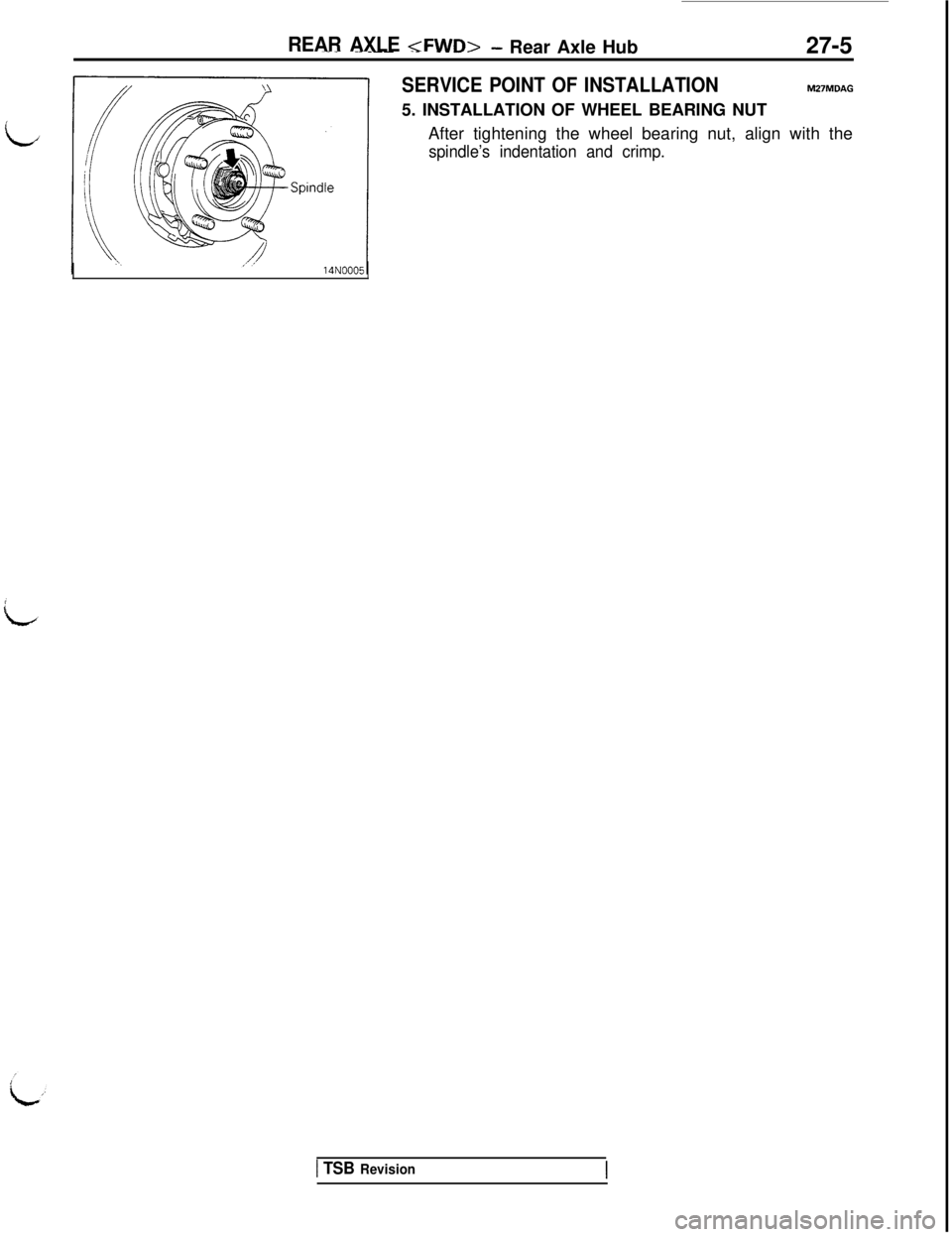
SERVICE POINT OF INSTALLATIONtu27MDAG5. INSTALLATION OF WHEEL BEARING NUT
After tightening the wheel bearing nut, align with the
spindle’s indentation and crimp.
1 TSB Revision
Page 602 of 1146
27-6
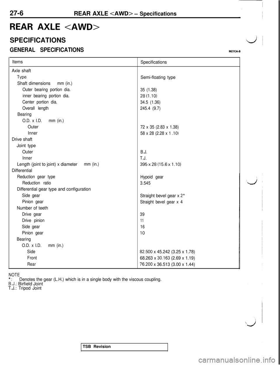
REAR AXLE tAWD> - Specifications
REAR AXLE
SPECIFICATIONS&L/j ~
GENERAL SPECIFICATIONSM27CA-8
Items
Axle shaft
We
Shaft dimensionsmm (in.)
Outer bearing portion dia.
inner bearing portion dia.
Center portion dia.
Overall length
Bearing
O.D. x I.D.mm (in.)
Outer
Inner
Drive shaft
Joint type
Outer
Inner
Length (joint to joint) x diametermm (in.)
Differential
Reduction gear type
Reduction ratio
Differential gear type and configuration
Side gear
Pinion gear
Number of teeth
Drive gear
Drive pinion
Side gear
Pinion gear
Bearing
O.D. x I.D.mm (in.)
Side
Front
Rear
Specifications
Semi-floating type
35 (1.38)
28(1.10)
34.5 (1.36)
245.4 (9.7)
72 x 35 (2.83 x 1.38)
58 x 28 (2.28 x 1
.I 0)
B.J.
T.J.
395x28(15.6x1.10)
Hypoid gear
3.545
Straight bevel gear x 2”
Straight bevel gear x 4
39
11
16
IO
82.500 x 45.242 (3.25 x 1.78)
68.263 x
30.163 (2.69 x 1.19)
76.200 x 36.513 (3.00 x 1.44)
NOTE*.Denotes the gear (L.H.) which is in a single body with the viscous coupling.B:J.: Birfield JointT.J.: Tripod JointTSB Revision
Page 603 of 1146
![MITSUBISHI 3000GT 1991 Service Manual REAR AXLE <AWD> - Specifications
SERVICE SPECIFICATIONS27-7M27CEB
L
ItemsSpecifications
Standard value
Rear wheel bearing rotation torqueN
(Ibs.) [Nm (in.lbs.)l12 (2.6) lo.7 (6)] or less
Setting of T MITSUBISHI 3000GT 1991 Service Manual REAR AXLE <AWD> - Specifications
SERVICE SPECIFICATIONS27-7M27CEB
L
ItemsSpecifications
Standard value
Rear wheel bearing rotation torqueN
(Ibs.) [Nm (in.lbs.)l12 (2.6) lo.7 (6)] or less
Setting of T](/img/19/57085/w960_57085-602.png)
REAR AXLE
SERVICE SPECIFICATIONS27-7M27CEB
L
ItemsSpecifications
Standard value
Rear wheel bearing rotation torqueN
(Ibs.) [Nm (in.lbs.)l12 (2.6) lo.7 (6)] or less
Setting of T.J. boot length
mm (in.)
85 +_ 3 (3.35 f .12)
Final drive gear backlash
mm (in.)0.11 -0.16(.004-.006)
Differential gear backlash (Limited slip differential)
mm (in.)0.03 - 0.09 (.0012 -.0035)
Drive pinion rotation torque
Nm
(in.lbs.)
With oil seal
New part (with rust-prevention oil)0.5 - 0.7 (4 - 6)
New part/reusable part (gear oil application)
0.35
- 0.45 (3 - 4)
Without oil seal
New part (with rust-prevention oil)
0.3-0.5(3-4)
New part/reusable part (gear oil application)0.15 - 0.25 (1 - 2)
Limit
Rear axle total backlashmm (in.)5 (2)
Drive gear runout
mm (in.)0.05 (.002)
Rear wheel bearing end playmm (in.)0.8 (031)
LUBRICANTSM27CD.~Items
Specified lubricantsQuantity
i
Rear axle gear oilHypoid Gear Oil API classification GL-5 or higher1 .I lit. (1.2 qts.)
Above -23°C (-10°F) SAESO, 85W-90,8OW-90From -34°C (-30°F) to -23°C (-10°F) SAE 8OW, 8OW-90
Below -34°C (-30°F) SAE 75W
B.J. boot grease
T.J. boot greaseRepair kit grease125 g (4.41 oz.)
135 g (4.76 oz.)
SEALANTS AND ADHESIVESM27CE-.
I7.Specrfred sealants and adhesives
Drive gear threaded hole
Vent plug
Differential cover3M Stud Locking Part No. 4170 or equivalent
3M ATD Part No. 8663 or equivalentTSB Revision
Page 604 of 1146
27-8REAR AXLE
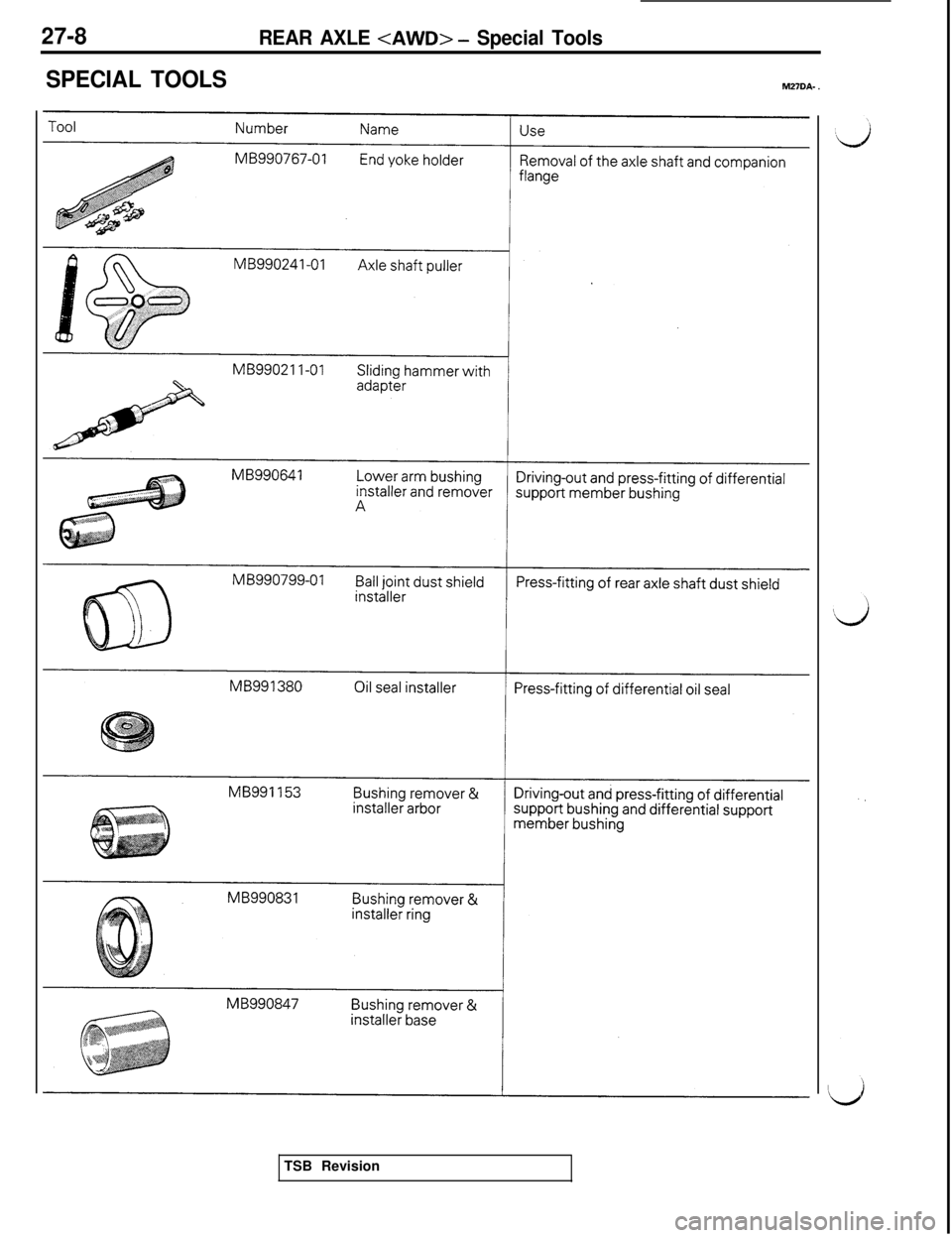
SPECIAL TOOLSMZ?DA- .
MB990799-01TSB Revision
Page 605 of 1146
REAR AXLE
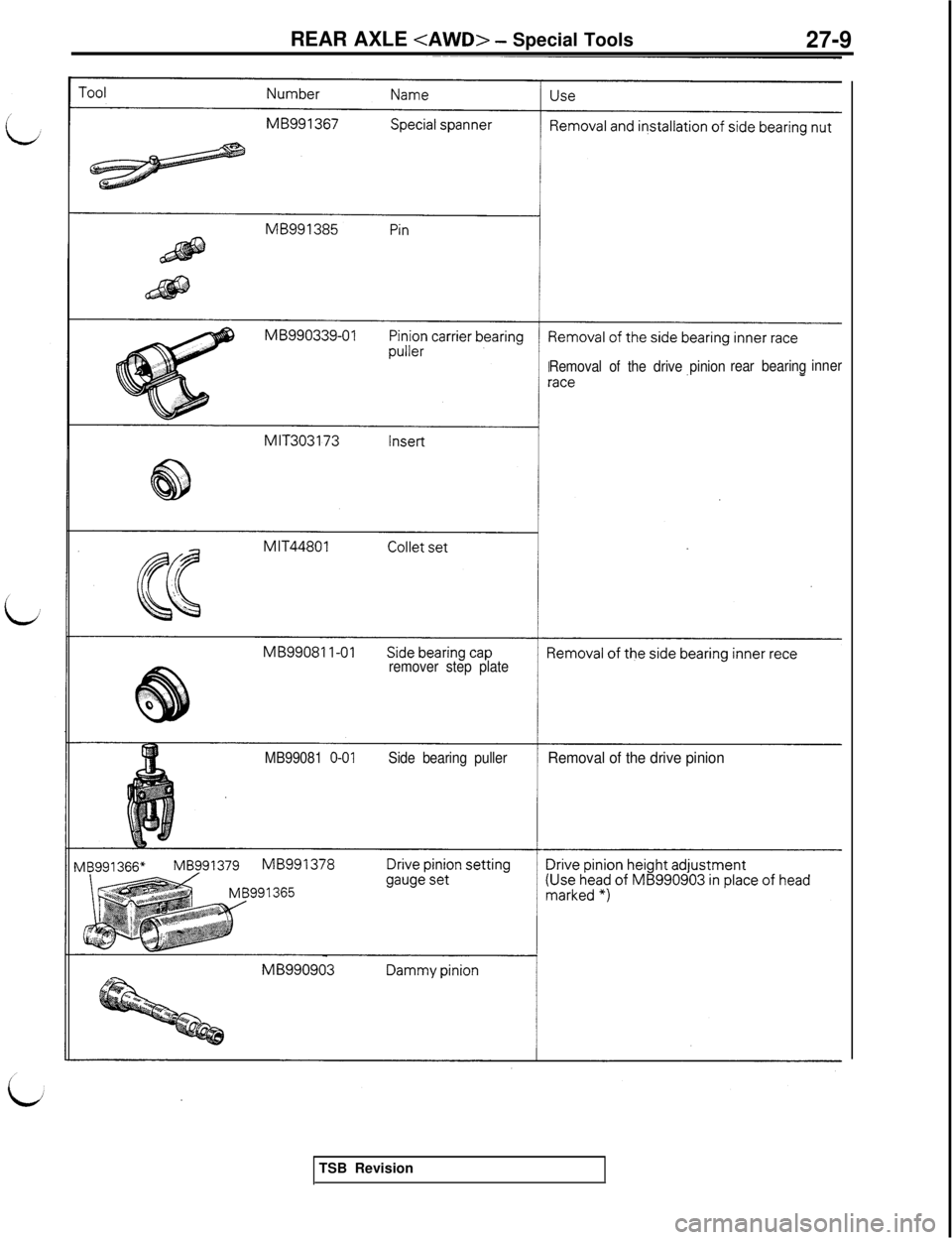
Removal of the drive pinionrear bearinginner
remover step plate
MB99081
O-01Side bearing pullerRemoval of the drive pinionTSB Revision
Page 606 of 1146
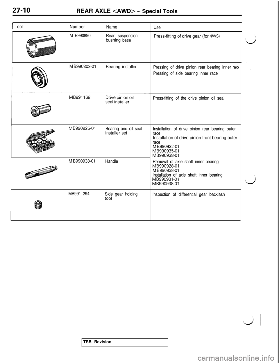
27-10
REAR AXLE
ITool
Number
Name
M B990890
Rear suspension
bushing .base
M B990802-01Bearing installer
MB990925-01
Bearing and oil sealinstaller set
M
8990938-01Handle
MB991 294
Side gear holding
toolUse
Press-fitting of drive gear (for 4WS)
Pressing of drive pinion rear bearing inner ract
Pressing of side bearing inner race
Press-fitting of the drive pinion oil seal
Installation of drive pinion rear bearing outer
raceInstallation of drive pinion front bearing outerraceM B990932-01MB990935-01MB990938-01
Removal of axle shaft inner bearing Removal of axle shaft inner bearing
MB990928-01MB990928-01M B990938-01M B990938-01Installation of axle shaft inner bearing Installation of axle shaft inner bearingMB990931-01MB990931-01MB990938-01MB990938-01
Inspection of differential gear backlashTSB Revision
Page 607 of 1146
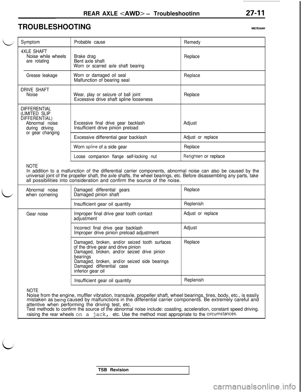
li
LREAR AXLE
TROUBLESHOOTINGM27EAAH
SymptomProbable cause
Remedy
4XLE SHAFT
Noise while wheelsBrake drag
Replace
are rotatingBent axle shaftWorn or scarred axle shaft bearing
Grease leakageWorn or damaged oil seal
Malfunction of bearing sealReplace
DRIVE SHAFTNoiseWear, play or seizure of ball jointExcessive drive shaft spline loosenessReplace
DIFFERENTIAL
(LIMITED SLIP
DIFFERENTIAL)Abnormal noise
during driving
or gear changing
NOTE
Excessive final drive gear backlashInsufficient drive pinion preload
Excessive differential gear backlash
Worn
spline of a side gear
Loose companion flange self-locking nut
Adjust
Adjust or replace
Replace
Retighten or replace
In addition to a malfunction of the differential carrier components, abnormal noise can also be caused by the
universal joint of the propeller shaft, the axle shafts, the wheel bearings, etc. Before disassembling any parts, takeall possibilities into consideration and confirm the source of the noise.
Abnormal noisewhen cornering
Gear noiseDamaged differential gears
Damaged pinion shaft
Insufficient gear oil quantity
Improper final drive gear tooth contact
adjustment
Replace
Replenish
Adjust or replace
Incorrect final drive gear backlash
Improper drive pinion preload adjustmentAdjust
Damaged, broken, and/or seized tooth surfacesof the drive gear and drive pinionDamaged, broken, and/or seized drive pinion
bearingsReplace
Damaged, broken, and/or seized side bearings
Damaged differential case
inferior gear oil
NOTE
Insufficient gear oil quantityReplenishNoise from the engine, muffler vibration, transaxle, propeller shaft, wheel bearings, tires, body, etc., is easily
mistaken as
being caused by malfunctions in the differential carrier components. Be extremely careful and
attentive when performing the driving test, etc.
Test methods to confirm the source of the abnormal noise include: coasting, acceleration, constant speed driving.
raising the rear wheels
on a jack, etc. Use the method most appropriate to the crrcumstances.TSB Revision
Page 608 of 1146
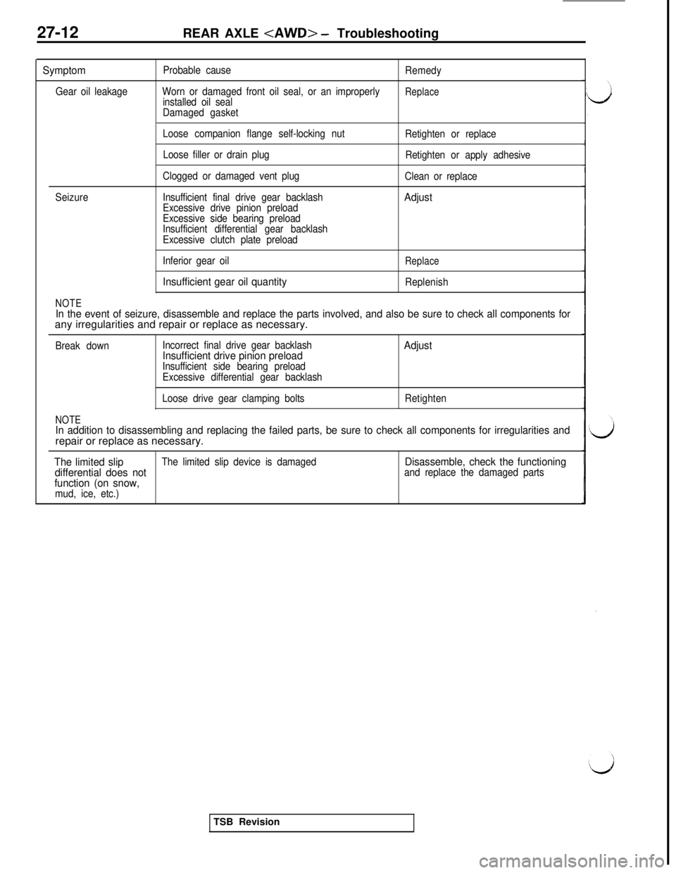
27-12REAR AXLE
Symptom
Gear oil leakageProbable cause
Worn or damaged front oil seal, or an improperly
installed oil seal
Damaged gasketRemedyReplace
Loose companion flange self-locking nut
Loose filler or drain plugRetighten or replace
Retighten or apply adhesive
SeizureClogged or damaged vent plug
Insufficient final drive gear backlash
Excessive drive pinion preload
Excessive side bearing preloadClean or replace
Adjust
Insufficient differential gear backlash
Excessive clutch plate preload
NOTE
Inferior gear oil
Insufficient gear oil quantity
Replace
Replenish
In the event of seizure, disassemble and replace the parts involved, and also be sure to check all components forany irregularities and repair or replace as necessary.
Break downIncorrect final drive gear backlashInsufficient drive pinion preloadInsufficient side bearing preload
Adjust
Excessive differential gear backlash
NOTE
Loose drive gear clamping boltsRetighten
In addition to disassembling and replacing the failed parts, be sure to check all components for irregularities andrepair or replace as necessary.
The limited slipThe limited slip device is damagedDisassemble, check the functioning
differential does notand replace the damaged partsfunction (on snow,mud, ice, etc.)TSB Revision
Page 609 of 1146
REAR AXLE
,,rmr
SERVICE ADJUSTMENT PROCEDURES
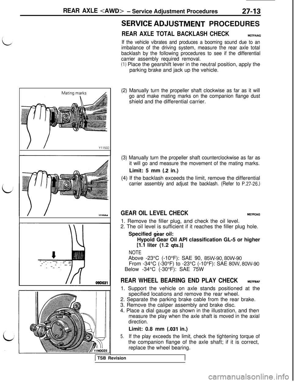
REAR AXLE TOTAL BACKLASH CHECKM27FAAG
If the vehicle vibrates and produces a booming sound due to an
imbalance of the driving system, measure the rear axle total
backlash by the following procedures to see if the differential
carrier assembly required removal.
(1) Place the gearshift lever in the neutral position, apply the
parking brake and jack up the vehicle.
(2) Manually turn the propeller shaft clockwise as far as it will
go and make mating marks on the companion flange dustshield and the differential carrier.
(3) Manually turn the propeller shaft counterclockwise as far as
it will go and measure the movement of the mating marks.Limit: 5 mm
(.2 in.)
(4) If the backlash exceeds the limit, remove the differential
carrier assembly and adjust the backlash. (Refer to P.27-26.)
GEAR OIL LEVEL CHECKM27FCAG1. Remove the filler plug, and check the oil level.
2. The oil level is sufficient if it reaches the filler plug hole.
Specified
gear oil:
Hypoid Gear Oil API classification GL-5 or higher
[l.l liter (1.2 q&J]
NOTEAbove -23°C (-10°F): SAE 90,
85W-90, 8OW-90From -34°C (-30°F) to -23°C (-10°F): SAE
8OW, 8OW-90Below -34°C (-30°F): SAE 75W
REAR WHEEL BEARING END PLAY CHECKM27FBAF1. Support the vehicle on axle stands positioned at the
specified locations and remove the rear wheel.
2. Separate the parking brake cable from the rear brake.
3. Remove the caliper assembly and brake disc.
4. Place a dial gauge as shown in the illustration, and then
measure the play when the axle shaft is moved in the axial
direction.Limit: 0.8 mm
(.031 in.)
5.If the play exceeds the limit, check the tightening torque ofthe companion flange of the axle shaft; if it is correct,
replace the wheel bearing.
1 TSB RevisionI
Page 610 of 1146
27-14REAR AXLE
Incorrect
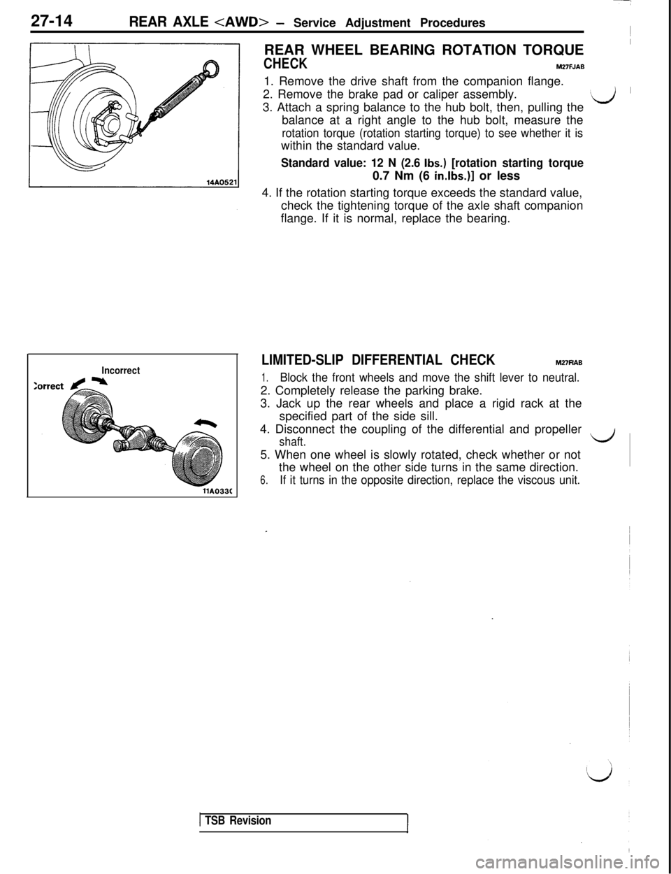
llA033CREAR WHEEL BEARING ROTATION TORQUE
I
CHECKM27FJAB1. Remove the drive shaft from the companion flange.
2. Remove the brake pad or caliper assembly.
3. Attach a spring balance to the hub bolt, then, pulling the
‘d ’balance at a right angle to the hub bolt, measure the
rotation torque (rotation starting torque) to see whether it iswithin the standard value.
Standard value: 12 N (2.6 Ibs.) [rotation starting torque0.7 Nm (6
in.lbs.)] or less
4. If the rotation starting torque exceeds the standard value,
check the tightening torque of the axle shaft companion
flange. If it is normal, replace the bearing.
LIMITED-SLIP DIFFERENTIAL CHECKM27FlAB
1.Block the front wheels and move the shift lever to neutral.2. Completely release the parking brake.
3. Jack up the rear wheels and place a rigid rack at the
specified part of the side sill.
4. Disconnect the coupling of the differential and propeller
shaft.LJ5. When one wheel is slowly rotated, check whether or not
the wheel on the other side turns in the same direction.
6.If it turns in the opposite direction, replace the viscous unit.
1 TSB Revision