MITSUBISHI 3000GT 1991 Service Manual
Manufacturer: MITSUBISHI, Model Year: 1991, Model line: 3000GT, Model: MITSUBISHI 3000GT 1991Pages: 1146, PDF Size: 76.68 MB
Page 591 of 1146
FRONT AXLE - Drive Shaft26-15
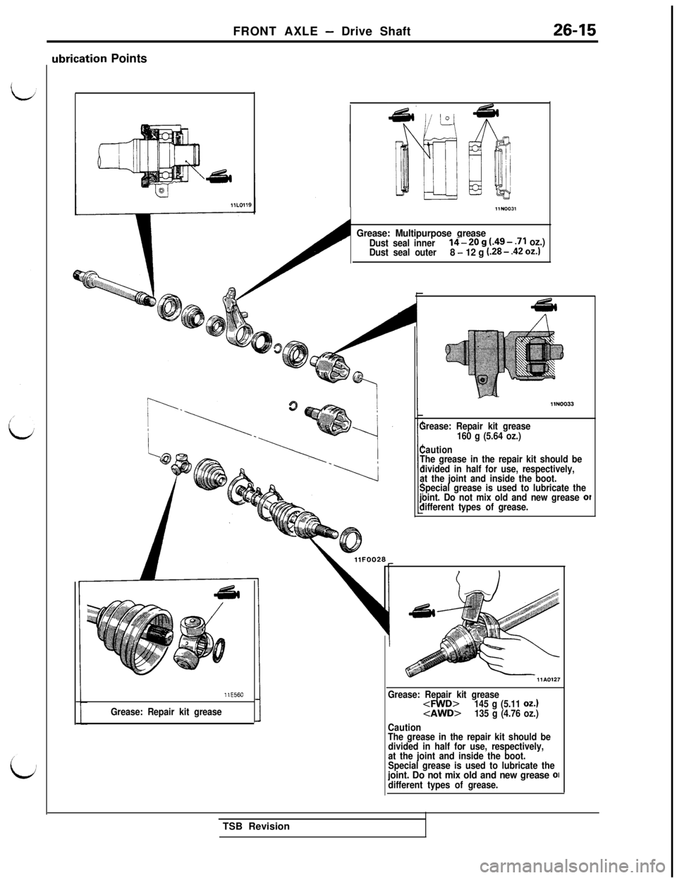
ubrication Points
Grease: Multipurpose greaseDust seal inner14-2Og(.49-.71 oz.)Dust seal outer8 - 12 g (.28- .42 oz.)
llE560
Grease: Repair kit greaseGrease: Repair kit grease
160 g (5.64 oz.)
Caution
The grease in the repair kit should be
divided in half for use, respectively,
at the joint and inside the boot.
Special grease is used to lubricate the
joint. Do not mix old and new grease
ofdifferent types of grease.
Grease: Repair kit grease
145 g (5.11 oz.)
Caution
The grease in the repair kit should be
divided in half for use, respectively,
at the joint and inside the boot.
Special grease is used to lubricate the
joint. Do not mix old and new grease OIdifferent types of grease.TSB Revision
Page 592 of 1146
26-16FRONT AXLE - Drive ShaftllNOO3611AOO76
1
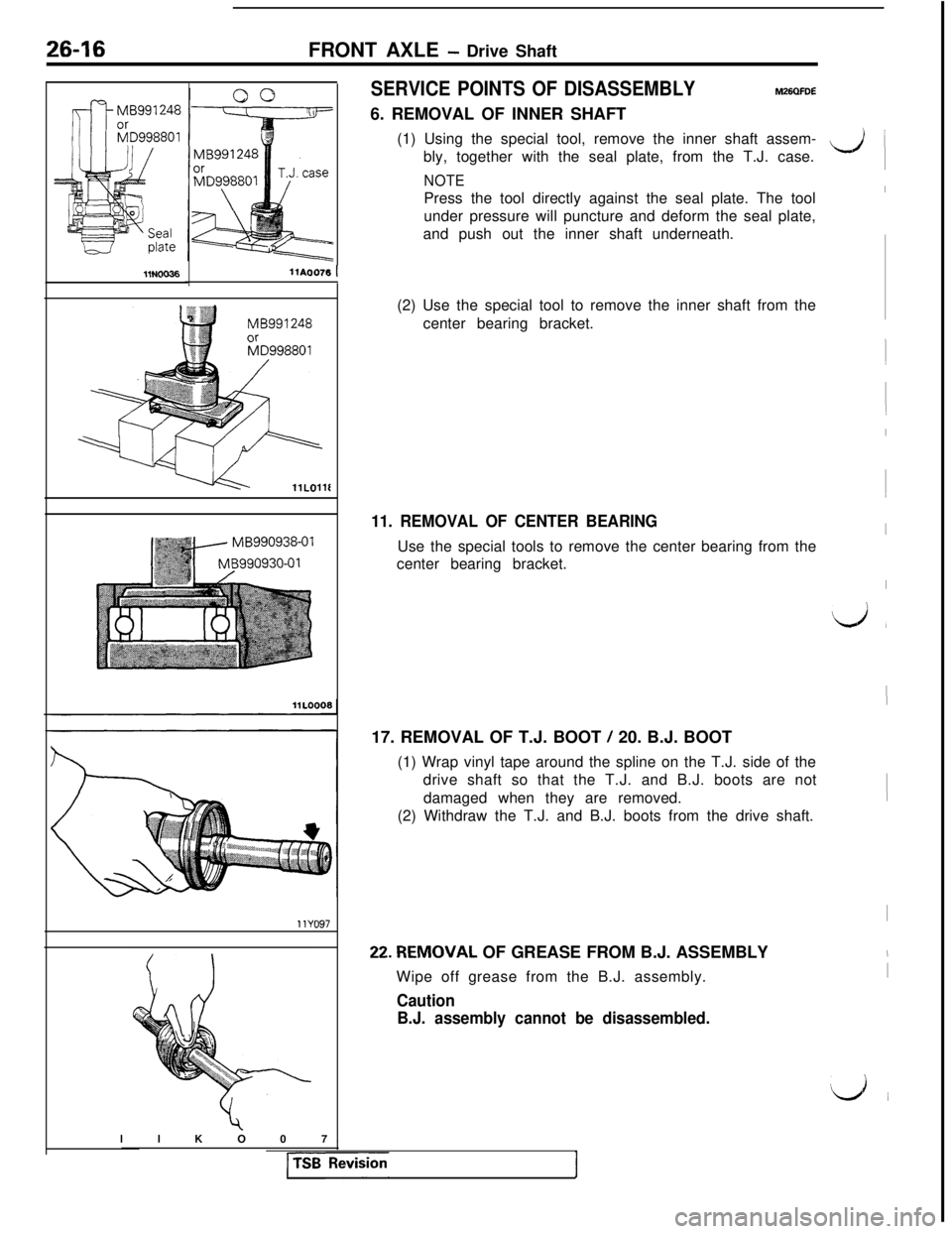
SERVICE POINTS OF DISASSEMBLYM26QFDE6. REMOVAL OF INNER SHAFT
(1) Using the special tool, remove the inner shaft assem-
bly, together with the seal plate, from the T.J. case.
NOTEPress the tool directly against the seal plate. The tool
under pressure will puncture and deform the seal plate,
and push out the inner shaft underneath.
(2) Use the special tool to remove the inner shaft from the
center bearing bracket.
11. REMOVAL OF CENTER BEARINGUse the special tools to remove the center bearing from the
center bearing bracket.
17. REMOVAL OF T.J. BOOT
/ 20. B.J. BOOT
(1) Wrap vinyl tape around the spline on the T.J. side of the
drive shaft so that the T.J. and B.J. boots are not
damaged when they are removed.
(2) Withdraw the T.J. and B.J. boots from the drive shaft.22.REMOVAL OF GREASE FROM B.J. ASSEMBLY
Wipe off grease from the B.J. assembly.
Caution
B.J. assembly cannot be disassembled.llKO07
1
I
-,il
I
I
(
I
1
I
I
Lj,
I
I
I
I
I
‘d i
Page 593 of 1146
FRONT AXLE - Drive Shaft26-17
INSPECTIONM26QGDD
l Check the drive shaft for damage, bending or corrosion.
l Check the inner shaft for damage, bending or corrosion.
l Check the drive shaft splines for wear or damage.
l Check the inner shaft splines for wear or damage.
lCheck for entry of water and/or foreign material into B.J.
l Check the spider assembly for roller rotation, wear or
corrosion.
lCheck the groove inside T.J. case for wear of corrosion.
l Check the boots for deterioration, damage or cracking.
l Check the center bearing for seizure, discoloration or
roughness of rolling surface.
l Check the dust cover for damage or deterioration.
SERVICE POINTS OF REASSEMBLYM26QHDF
20. INSTALLATION OF B.J. BOOT
/ 17. T.J. BOOT
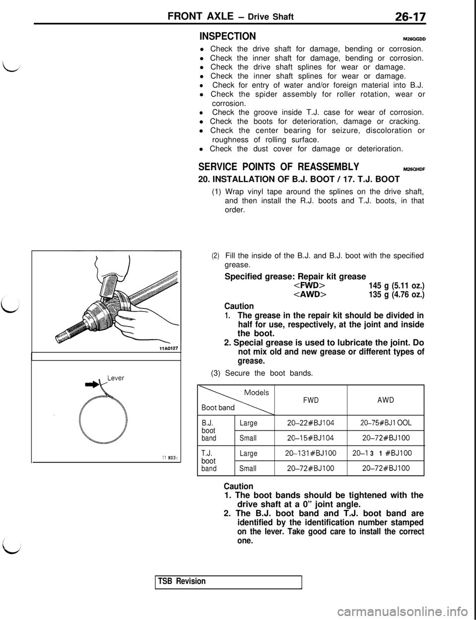
(1) Wrap vinyl tape around the splines on the drive shaft,
and then install the R.J. boots and T.J. boots, in that
order.
11 K03:
(2)Fill the inside of the B.J. and B.J. boot with the specified
grease.
Specified grease: Repair kit grease
Caution
1.The grease in the repair kit should be divided in
half for use, respectively, at the joint and insidethe boot.
2. Special grease is used to lubricate the joint. Do
not mix old and new grease or different types of
grease.(3) Secure the boot bands.
FWDAWD
B.J.bootband
T.J.
bootbandLarge20-22#BJ104
20-75#BJl OOL
Small20-I 5#BJ10420-72#BJlOO
Large20-131#BJlOO20-I 31 #BJlOO
Small20-72#BJlOO20-72#BJlOO
Caution1. The boot bands should be tightened with the
drive shaft at a 0” joint angle.
2. The B.J. boot band and T.J. boot band are
identified by the identification number stamped
on the lever. Take good care to install the correct
one.
TSB Revision
Page 594 of 1146
26-18
FRONT AXLE - Drive Shaft
llE56011 LOO64MB990938-01MB990932-01
11L0010
Dust seal innerMB990890-01
llLOO9'3-
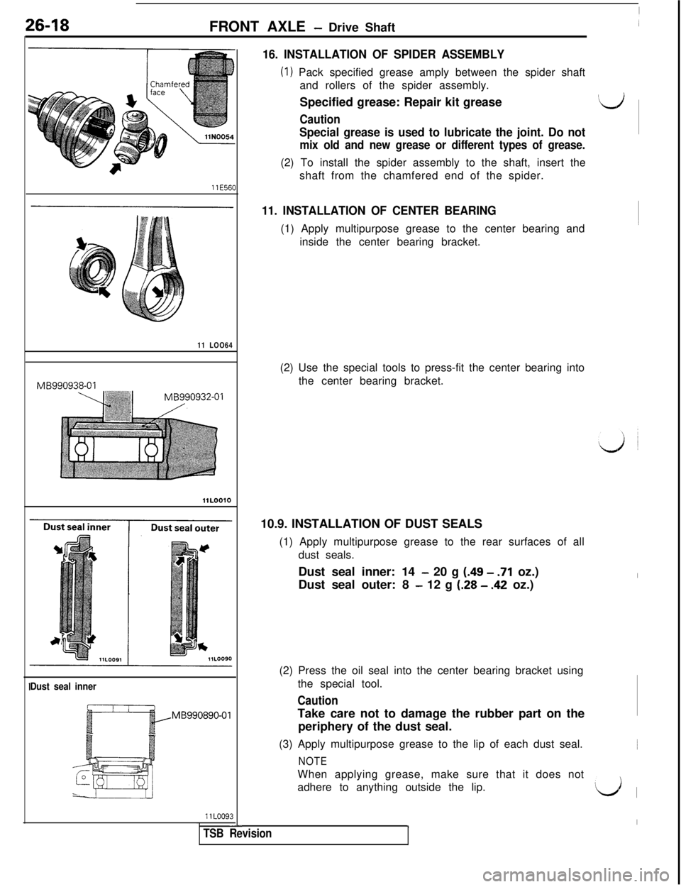
16. INSTALLATION OF SPIDER ASSEMBLY
(1) Pack specified grease amply between the spider shaft
and rollers of the spider assembly.
Specified grease: Repair kit grease
Id
Caution
Special grease is used to lubricate the joint. Do not
mix old and new grease or different types of grease.(2) To install the spider assembly to the shaft, insert the
shaft from the chamfered end of the spider.
11. INSTALLATION OF CENTER BEARING(1) Apply multipurpose grease to the center bearing and
inside the center bearing bracket.
(2) Use the special tools to press-fit the center bearing into
the center bearing bracket.
10.9. INSTALLATION OF DUST SEALS
(1) Apply multipurpose grease to the rear surfaces of all
dust seals.
Dust seal inner: 14
- 20 g (.49 - .71 oz.)
Dust seal outer: 8
- 12 g (.28 - .42 oz.)
(2) Press the oil seal into the center bearing bracket using
the special tool.
CautionTake care not to damage the rubber part on the
periphery of the dust seal.
(3) Apply multipurpose grease to the lip of each dust seal.
NOTEWhen applying grease, make sure that it does not
adhere to anything outside the lip.
Id 1
1I
TSB Revision
Page 595 of 1146
FRONT AXLE - Drive Shaft26-19MB990934-01
Dust seal outerr -jMB990890-01
ler shaft
I Inner
tshaft‘; assembly
llNOO35T.J. case
w
llN0037
-“’
@Grease
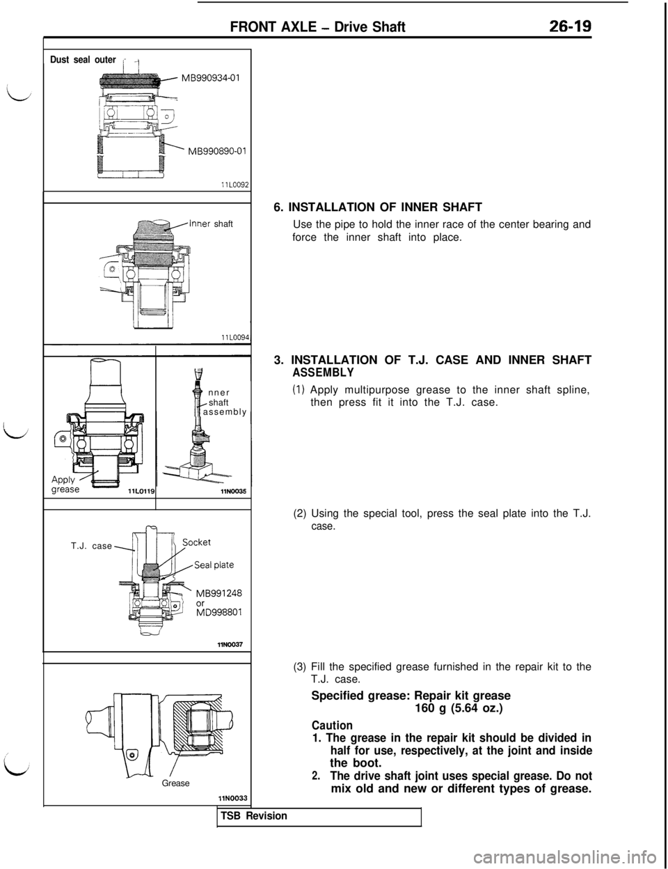
llN00336. INSTALLATION OF INNER SHAFT
Use the pipe to hold the inner race of the center bearing and
force the inner shaft into place.
3. INSTALLATION OF T.J. CASE AND INNER SHAFT
ASSEMBLY
(1) Apply multipurpose grease to the inner shaft spline,
then press fit it into the T.J. case.
(2) Using the special tool, press the seal plate into the T.J.
case.
TSB Revision(3) Fill the specified grease furnished in the repair kit to the
T.J. case.
Specified grease: Repair kit grease
160 g (5.64 oz.)
Caution
1. The grease in the repair kit should be divided in
half for use, respectively, at the joint and insidethe boot.
2.The drive shaft joint uses special grease. Do notmix old and new or different types of grease.
Page 596 of 1146
26-20
FRONT AXLE - Drive Shaft
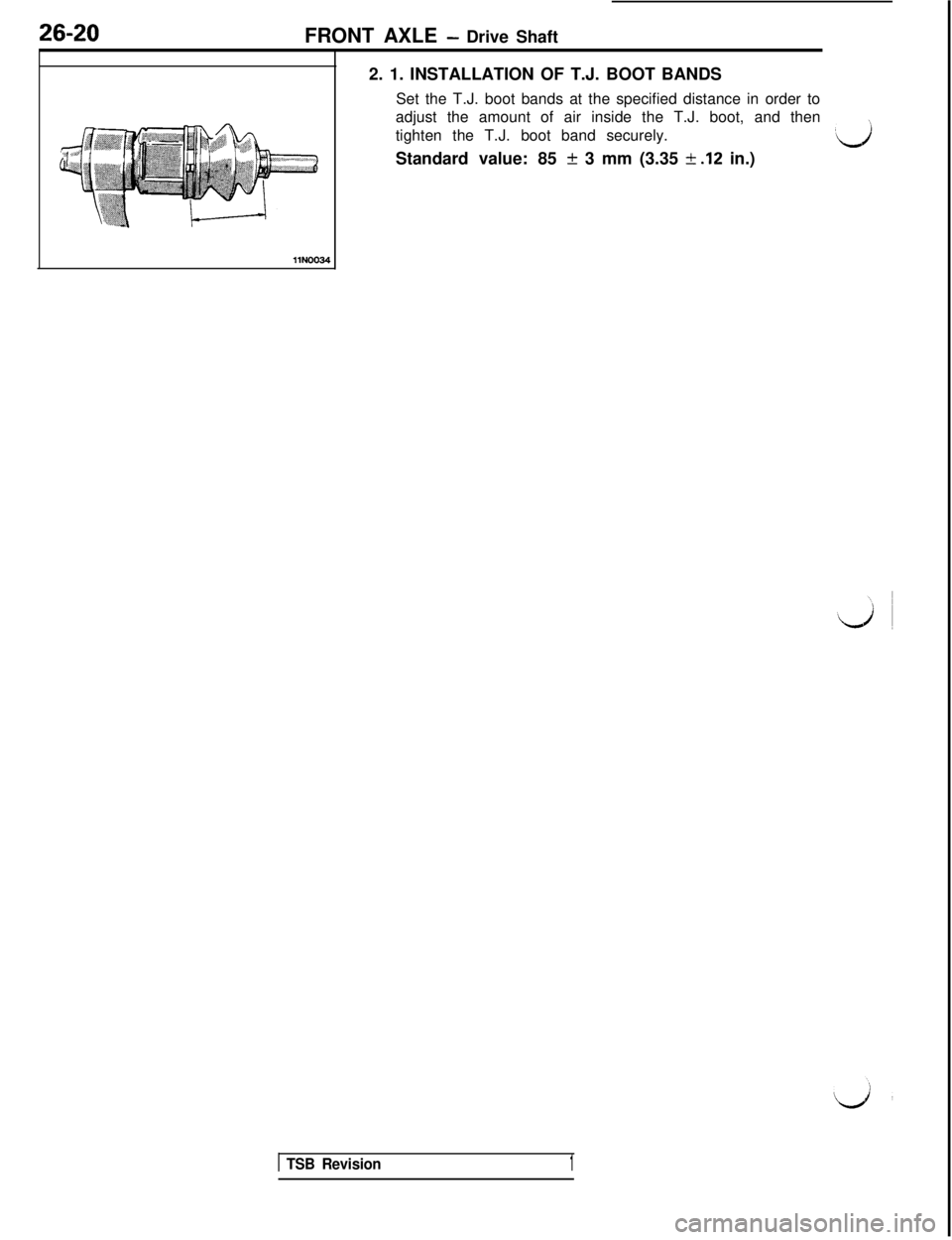
2. 1. INSTALLATION OF T.J. BOOT BANDS
Set the T.J. boot bands at the specified distance in order to
adjust the amount of air inside the T.J. boot, and then
tighten the T.J. boot band securely.
‘dStandard value: 85 + 3 mm (3.35
k .12 in.)llN0034
1 TSB Revision1
Page 597 of 1146
27-1
REAR AXLE
CONTENTSM27AA- -~
REAR AXLE
AXLE SHAFT. . . . . . . . . . . . . . . . . . . . . . . . . . . . . . . . . . . . . . . . . . . . . . . . . . . . . . . .15
DIFFERENTIAL CARRIER. . . . . . . . . . . . . . . . . . . . . . . .._..........24
DRIVE SHAFT
. . . . . . . . . . . . . . . . . . . . . . . . . . . . . . . . . . . . . . . . . . . . . . . . . . . . . . . .18
LSD CASE ASSEMBLY. . . . . . . . . . . . . . . . . . . . . . . . . . . . . . .._.......39
SERVICE ADJUSTMENT PROCEDURES
. . . . . . . .13
Gear OilLevelCheck. . . . . . . . . . . . . . . . . . . . . . . . . . . . . . . . . . . . . . . .13Limited-Slip Differential Check
. . . . . . . . . . .._...........14Rear Axle Total Backlash Check
. . . . . . . . . . . . . . . . . . . .13Rear Wheel Bearing End Play Check
_........... 13
Rear Wheel Bearing Rotation Torque
Check. . . . . . . . . . . . . . . . .._.............................................14
SPECIAL TOOLS. . . . . . . . . . . . . . . . . . . . . . . . . . . . . . . . . . . . . . . . . . . . . . . . . . . .8
SPECIFICATIONS................................................6General Specifications
....................................6Lubricants
............................................................7Sealants and Adhesives
....................................7Service Specifications
....................................7
TROUBLESHOOTING. . . . . . . . . . . . . . . . . . . . . . . . . . . . . . . . . . . . . . . .11Axle Shaft
Grease leakage
Noise while wheels are rotatingDifferential (Limited Slip Differential)
Abnormal noise during driving or
gear changing
Abnormal noise when cornering
Break down
Gear noise
Gear oil leakage
SeizureThe limited slip differential does
not function
Drive Shaft
Noise
REAR AXLE
REAR AXLEHUB. . . . . . . . . . . . . . . . . . . . . . . . . . . . . . . . . . . . . . . . . . . . . . . .
SERVICE ADJUSTMENT PROCEDURES........Rear Hub Rotary-sliding Resistance
(Torque)Inspection............................................Wheel Bearing End Play Inspection
................
SPECIFICATIONS................................................General Specifications
....................................Service Specifications
....................................
TROUBLESHOOTING. . . . . . . . . . .._....._.....................Abnormal Sound
24
3
3
32
2
2
2
Page 598 of 1146
27-2REAR AXLE
REAR AXLE
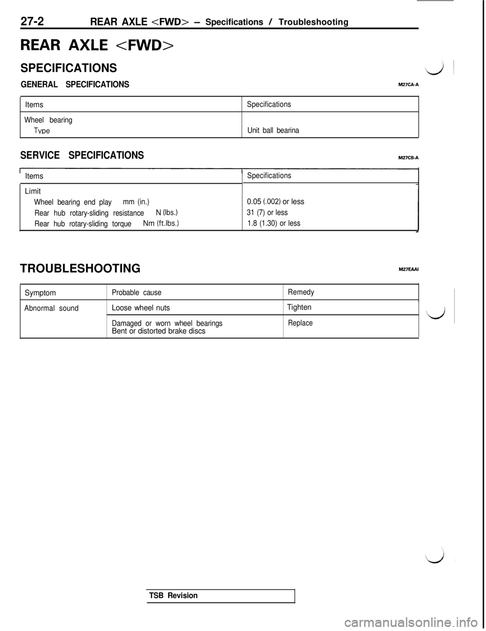
SPECIFICATIONS
GENERAL SPECIFICATIONSM27CA.A
Items
Wheel bearing
Tvoe
Specifications
Unit ball bearina
SERVICE SPECIFICATIONS
Items
Limit
Wheel bearing end playmm (in.)
Rear hub rotary-sliding resistance
N (Ibs.)
Rear hub rotary-sliding torqueNm (ft.lbs.)
Specifications
0.05 l.002) or less
31 (7) or less
1.8 (1.30) or lessTROUBLESHOOTING
SymptomProbable causeRemedy
Abnormal sound
Loose wheel nuts
Damaged or worn wheel bearingsBent or distorted brake discsTighten
Replace‘d
TSB Revision
Page 599 of 1146
REAR AXLE
llN00261 SERVICE ADJUSTMENT
PRbCEDURES
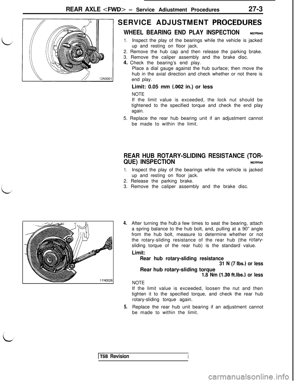
WHEEL BEARING END PLAY INSPECTIONM27FBAG
1.Inspect the play of the bearings while the vehicle is jacked
up and resting on floor jack.
2. Remove the hub cap and then release the parking brake.
3. Remove the caliper assembly and the brake disc.
4. Check the bearing’s end play.
Place a dial gauge against the hub surface; then move the
hub in the axial direction and check whether or not there is
end play.
Limit: 0.05 mm
(.002 in.) or less
NOTEIf the limit value is exceeded, the lock nut should be
tightened to the specified torque and check the end play
again.5. Replace the rear hub bearing unit if an adjustment cannot
be made to within the limit.
REAR HUB ROTARY-SLIDING RESISTANCE (TOR-
QUE) INSPECTION
M27FFAD
1.Inspect the play of the bearings while the vehicle is jacked
up and resting on floor jack.
2. Release the parking brake.
3. Remove the caliper assembly and the brake disc.
4.
5.After turning the
huba few times to seat the bearing, attach
a spring balance to the hub bolt, and, pulling at a 90” angle
from the hub bolt, measure to determine whether or not
the rotary-sliding resistance of the rear hub (the rotary-
sliding torque of the rear hub) is the standard value.
Limit:
Rear hub rotary-sliding resistance
31 N (7 Ibs.) or lessRear hub rotary-sliding torque
1.8 Nm (1.30 ft.lbs.) or less
NOTEIf the limit value is exceeded, loosen the nut and then
tighten it to the specified torque, and check the rear hub
rotary-sliding torque again.
Replace the rear hub unit bearing if an adjustment cannot
be made to within the limit.
[fsB RevisionI
Page 600 of 1146
27-4
REAR AXLE
REAR AXLE HUB
REMOVAL AND INSTALLATION
M27MA- -
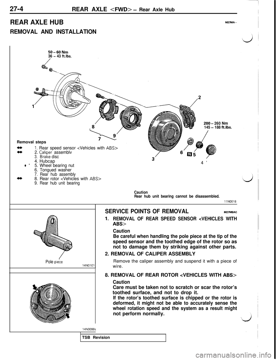
50-60Nm36 - 43 ftlbs.
200-260Nm145-188ftibs.Removal steps
4*4*1. Rear speed sensor
l *5. Wheel bearing nut4’6. Tongued washer7. Rear hub assembly4*8. Rear rotor
Caution
Rear hub unit bearing cannot be disassembled.
llN0018
Pole p&e14NOlO-7
SERVICE POINTS OF REMOVALM27MBAC
1.REMOVAL OF REAR SPEED SENSOR
Caution
Be careful when handling the pole piece at the tip of thespeed sensor and the toothed edge of the rotor so as
not to damage them by striking against other parts.
2. REMOVAL OF CALIPER ASSEMBLY
Remove the caliper assembly and suspend it with a piece of
wire.
8. REMOVAL OF REAR ROTOR
CautionCare must be taken not to scratch or scar the rotor’s
toothed surface, and not to drop it.
If the rotor’s toothed surface is chipped or the rotor is
deformed, it might not be able to accurately sense the
wheel rotation speed and the system as a result mightnot perform normally.
14NOO99ITSB Revision