MITSUBISHI 3000GT 1991 Service Manual
Manufacturer: MITSUBISHI, Model Year: 1991, Model line: 3000GT, Model: MITSUBISHI 3000GT 1991Pages: 1146, PDF Size: 76.68 MB
Page 621 of 1146
REAR AXLE
27-25
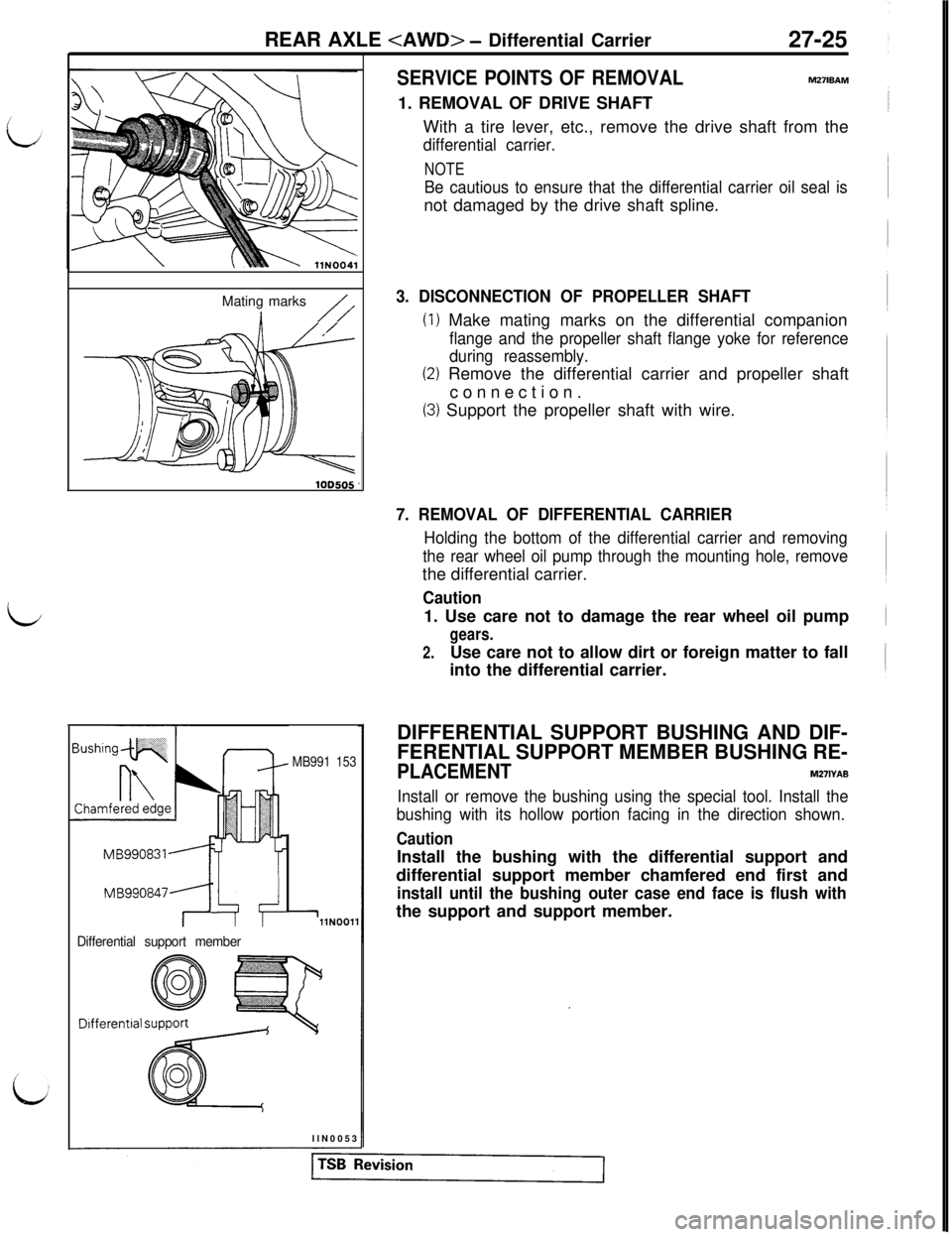
Mating marks
//
MB991 153
MBggo8477J=f 4
Differential support member
llNOOl1
DifferentialllN0053
SERVICE POINTS OF REMOVALm27wAm
1. REMOVAL OF DRIVE SHAFT
With a tire lever, etc., remove the drive shaft from the
differential carrier.
NOTE
Be cautious to ensure that the differential carrier oil seal isnot damaged by the drive shaft spline.
3. DISCONNECTION OF PROPELLER SHAFT
(1) Make mating marks on the differential companion
flange and the propeller shaft flange yoke for reference
during reassembly.
(2) Remove the differential carrier and propeller shaft
connection.
(3) Support the propeller shaft with wire.
7. REMOVAL OF DIFFERENTIAL CARRIER
Holding the bottom of the differential carrier and removing
the rear wheel oil pump through the mounting hole, removethe differential carrier.
Caution1. Use care not to damage the rear wheel oil pump
gears.
2.Use care not to allow dirt or foreign matter to fall
into the differential carrier.
DIFFERENTIAL SUPPORT BUSHING AND DIF-
FERENTIAL SUPPORT MEMBER BUSHING RE-
PLACEMENTM271YAB
Install or remove the bushing using the special tool. Install the
bushing with its hollow portion facing in the direction shown.
CautionInstall the bushing with the differential support and
differential support member chamfered end first and
install until the bushing outer case end face is flush withthe support and support member.
Page 622 of 1146
27-26
REAR AXLE
SERVICE POINTS OF INSTALLATION
7. INSTALLATION OF DIFFERENTIAL CARRIERm27lDAL
Install the rear wheel oil pump by inserting it through the
mounting hole and install the differential carrier securely.\yiIlYl61
Caution
Use care not to damage the rear wheel oil pump gears.
3. CONNECTION OF PROPELLER SHAFTAlign the mating marks on the flange yoke and the
companion flange to install the propeller shaft.
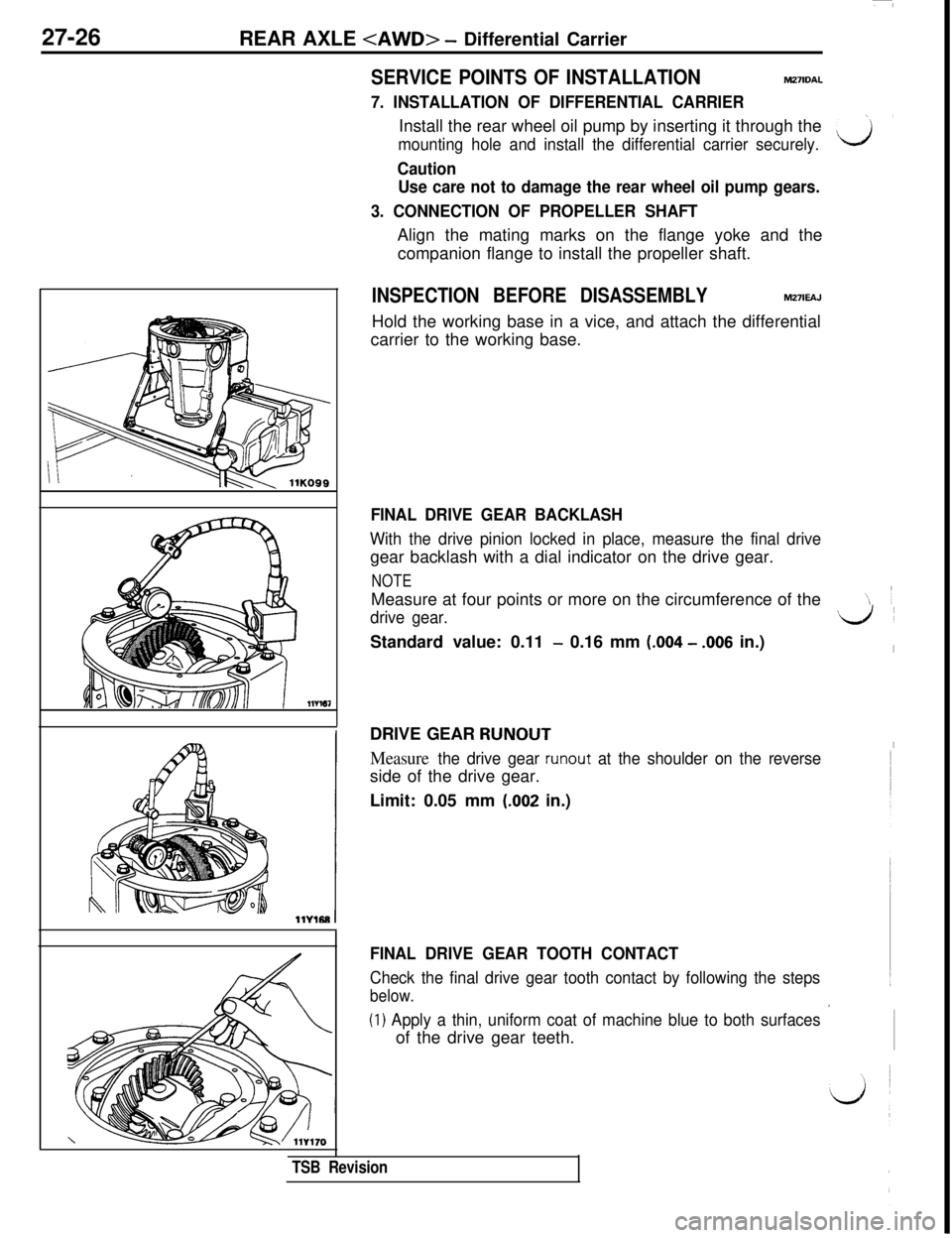
INSPECTION BEFORE DISASSEMBLYM27lEAJHold the working base in a vice, and attach the differential
carrier to the working base.
FINAL DRIVE GEAR BACKLASH
With the drive pinion locked in place, measure the final drivegear backlash with a dial indicator on the drive gear.
NOTEMeasure at four points or more on the circumference of the
drive gear.d’Standard value: 0.11
- 0.16 mm (.004 - .006 in.)IDRIVE GEAR
RUNOUTI
Measure the drive gear runout at the shoulder on the reverseside of the drive gear.
Limit: 0.05 mm
(.002 in.)
FINAL DRIVE GEAR TOOTH CONTACT
Check the final drive gear tooth contact by following the steps
below.
(1) Apply a thin, uniform coat of machine blue to both surfaces ’of the drive gear teeth.
TSB Revision
Page 623 of 1146
/
i.J
I
i
REAR AXLE
CT2flG0076
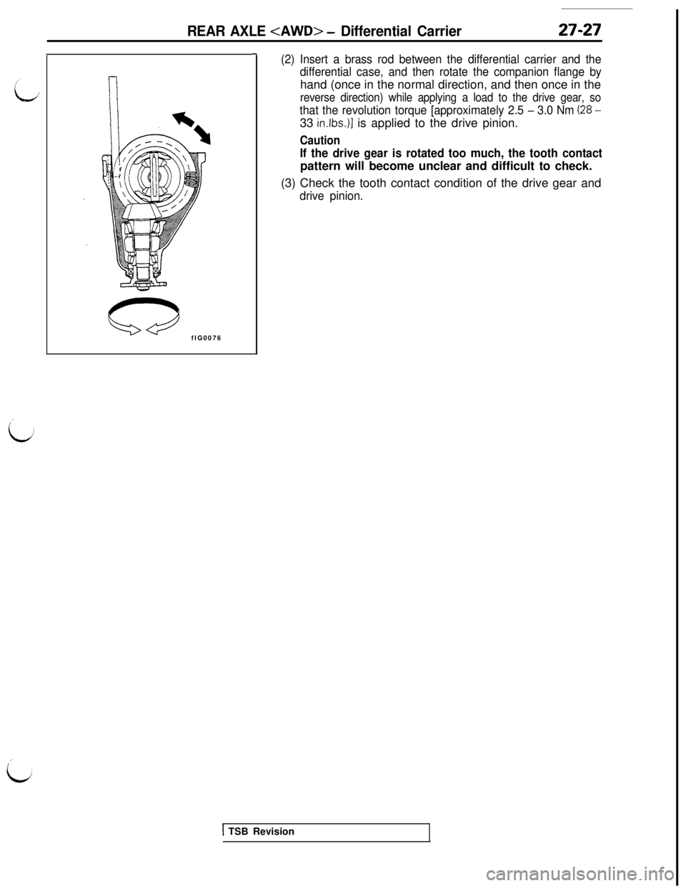
-7(2) Insert a brass rod between the differential carrier and the
differential case, and then rotate the companion flange byhand (once in the normal direction, and then once in the
reverse direction) while applying a load to the drive gear, so
that the revolution torque [approximately 2.5 - 3.0 Nm (28 -33
in.lbs.)] is applied to the drive pinion.
Caution
If the drive gear is rotated too much, the tooth contactpattern will become unclear and difficult to check.
(3) Check the tooth contact condition of the drive gear and
drive pinion.
1 TSB Revision
Page 624 of 1146
27-28
REAR AXLE
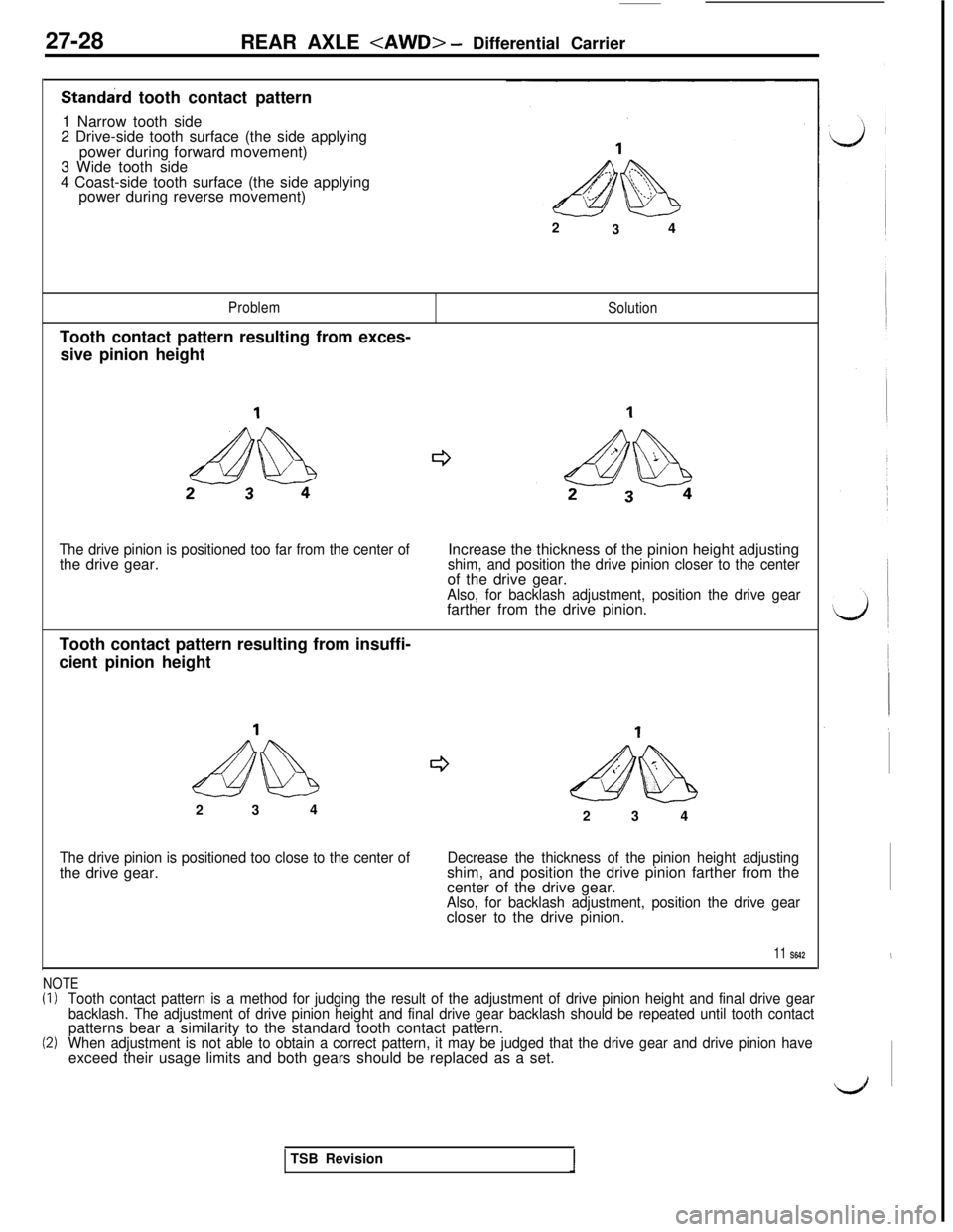
Standard tooth contact pattern
1 Narrow tooth side
2 Drive-side tooth surface (the side applying
power during forward movement)
3 Wide tooth side
4 Coast-side tooth surface (the side applying
power during reverse movement)
2
34
ProblemTooth contact pattern resulting from exces-
sive pinion heightSolution
The drive pinion is positioned too far from the center ofthe drive gear.Increase the thickness of the pinion height adjustingshim, and position the drive pinion closer to the centerof the drive gear.
Also, for backlash adjustment, position the drive gearfarther from the drive pinion.
Tooth contact pattern resulting from insuffi-
cient pinion height
ectdb
e52 34&$%$I$&2 3 4
The drive pinion is positioned too close to the center ofthe drive gear.Decrease the thickness of the pinion height adjustingshim, and position the drive pinion farther from the
center of the drive gear.
Also, for backlash adjustment, position the drive gearcloser to the drive pinion.
11 S642
NOTE(I)Tooth contact pattern is a method for judging the result of the adjustment of drive pinion height and final drive gear
backlash. The adjustment of drive pinion height and final drive gear backlash should be repeated until tooth contactpatterns bear a similarity to the standard tooth contact pattern.
(2)When adjustment is not able to obtain a correct pattern, it may be judged that the drive gear and drive pinion haveexceed their usage limits and both gears should be replaced as a set.
,
dTSB Revision
Page 625 of 1146
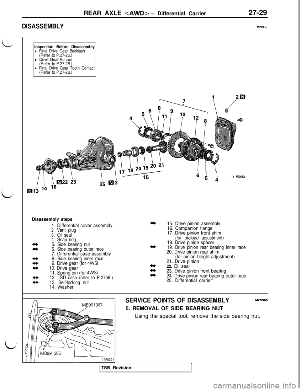
DISASSEMBLYREAR AXLE
M27lF- -
inspection Before Disassemblyl Final Drive Gear Backlash(Refer to P.27-26.)l Drive Gear Runout(Refer to P.27-26.)l Final Drive Gear Tooth Contact(Refer to P.27-26.)Disassembly steps
1. Differential cover assembly2.Vent plug
3.Oil seal
4.Snap ring4*5. Side bearing nut4*6. Side bearing outer race7. Differential case assembly4*8. Side bearing inner race4*9. Drive gear (for 4WS)4*10. Drive gear
11. Spring pin (for 4WS)4*12. LSD case (refer to P.2759.)4*13. Self-locking nut14:Washer
4*
4*
4*4*4*
64 111 FO032
15. Drive pinion assembly
16. Companion flange
17. Drive pinion front shim
(for preload adjustment)18. Drive pinion spacer19. Drive pinion rear bearing inner race20. Drive pinion rear shim
(for pinion height adjustment)
21. Drive pinion
22. Oil seal
23. Drive pinion front bearing
24. Drive pinion rear bearing outer race
25. Differential carrier’
SERVICE POINTS OF DISASSEMBLYM27lGBD5. REMOVAL OF SIDE BEARING NUT
Using the special tool, remove the side bearing nut.
TSB Revision
Page 626 of 1146
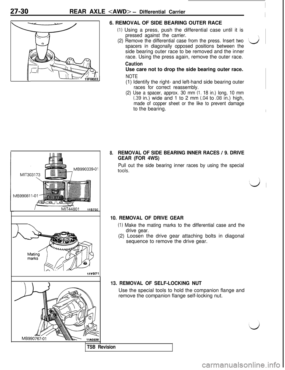
27-30REAR AXLE
VlB990811-01
J6. REMOVAL OF SIDE BEARING OUTER RACE
(I) Using a press, push the differential case until it is
pressed against the carrier.
(2) Remove the differential case from the press. Insert two
spacers in diagonally opposed positions between the‘dside bearing outer race to be removed and the inner
race. Using the press again, remove the outer race.
CautionUse care not to drop the side bearing outer race.
NOTE(1) Identify the right- and left-hand side bearing outer
races for correct reassembly.
(2) Use a spacer, approx. 30 mm (I. 18 in.) long, 10 mm
I.39 in.) wide and 1 to 2 mm (.04 to .08 in.) high,
made of copper sheet or the like to prevent damageto the bearing.
8.REMOVAL OF SIDE BEARING INNER RACES / 9. DRIVE
GEAR (FOR 4WS)
Pull out the side bearing inner races by using the special
tools.
10. REMOVAL OF DRIVE GEAR
(I) Make the mating marks to the differential case and the
drive gear.(2) Loosen the drive gear attaching bolts in diagonal
sequence to remove the drive gear.
13. REMOVAL OF SELF-LOCKING NUTUse the special tools to hold the companion flange and
remove the companion flange self-locking nut.
TSB Revision
Page 627 of 1146
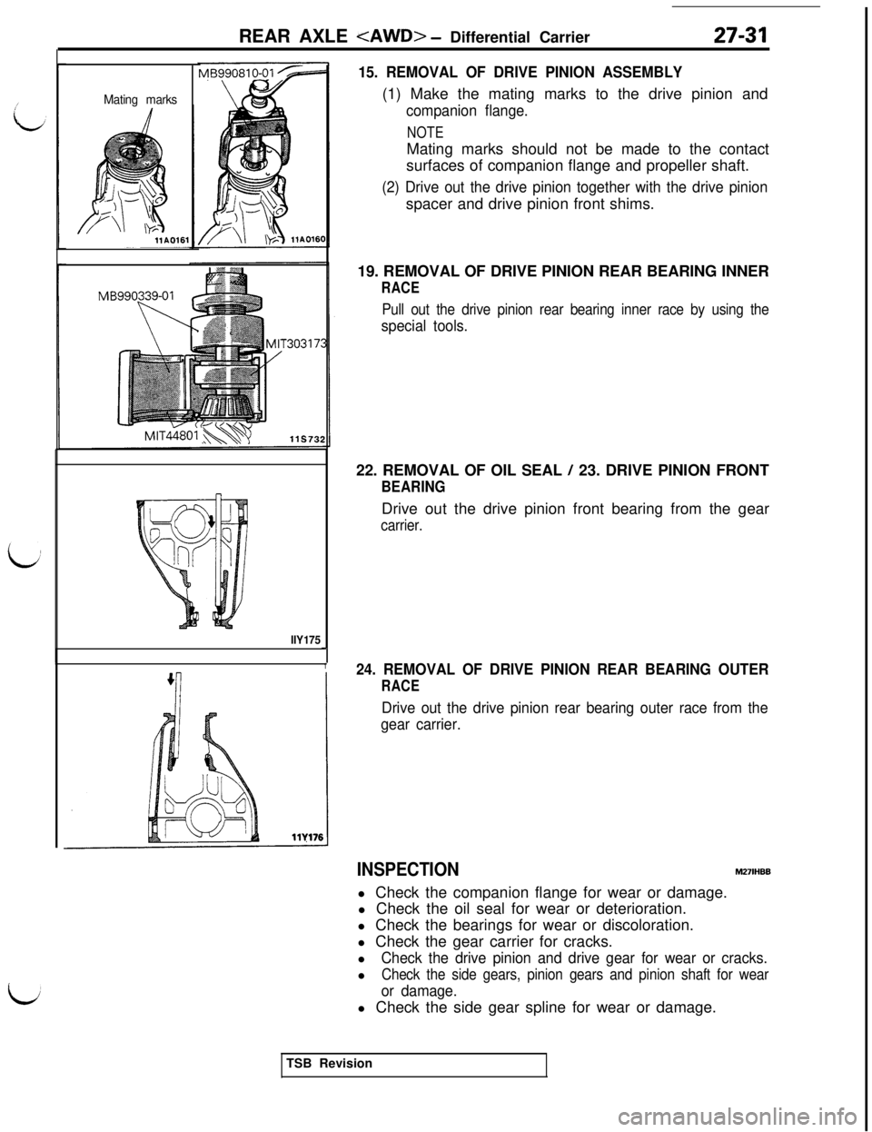
REAR AXLE
Mating marks
MB990339-01
llY175J
1
15. REMOVAL OF DRIVE PINION ASSEMBLY(1) Make the mating marks to the drive pinion and
companion flange.
NOTEMating marks should not be made to the contact
surfaces of companion flange and propeller shaft.
(2) Drive out the drive pinion together with the drive pinionspacer and drive pinion front shims.
19. REMOVAL OF DRIVE PINION REAR BEARING INNER
RACE
Pull out the drive pinion rear bearing inner race by using the
special tools.22. REMOVAL OF OIL SEAL
/ 23. DRIVE PINION FRONT
BEARINGDrive out the drive pinion front bearing from the gear
carrier.
24. REMOVAL OF DRIVE PINION REAR BEARING OUTER
RACE
Drive out the drive pinion rear bearing outer race from the
gear carrier.
INSPECTIONM27lHBBl Check the companion flange for wear or damage.
l Check the oil seal for wear or deterioration.
l Check the bearings for wear or discoloration.
l Check the gear carrier for cracks.
l
Check the drive pinion and drive gear for wear or cracks.l
Check the side gears, pinion gears and pinion shaft for wear
or damage.l Check the side gear spline for wear or damage.
TSB Revision
Page 628 of 1146
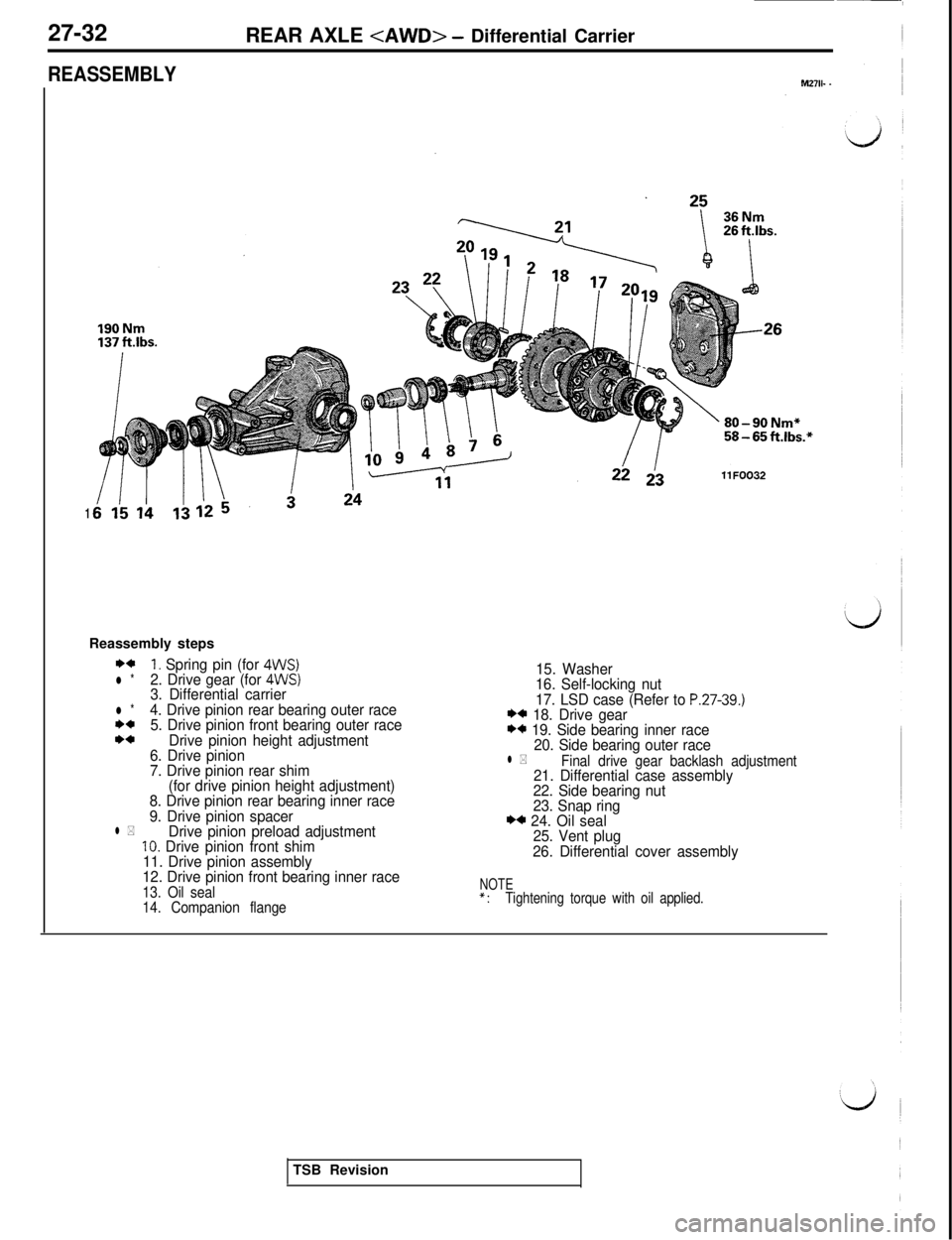
27-32
REAR AXLE
REASSEMBLYM2711- .
1Reassembly steps
**1. Spring pin (for 4WS)l *2. Drive gear (for 4WS)3. Differential carrierl *4. Drive pinion rear bearing outer race**5. Drive pinion front bearing outer race*aDrive pinion height adjustment
6. Drive pinion
7. Drive pinion rear shim
(for drive pinion height adjustment)
8. Drive pinion rear bearing inner race
9. Drive pinion spacer
l *Drive pinion preload adjustment10. Drive pinion front shim
11. Drive pinion assembly
12. Drive pinion front bearing inner race
13. Oil seal
14. Companion flange
15. Washer
16. Self-locking nut
17. LSD case (Refer to
P.27-39.)** 18. Drive gear** 19. Side bearing inner race
20. Side bearing outer race
l *Final drive gear backlash adjustment21. Differential case assembly
22. Side bearing nut
23. Snap ring
** 24. Oil seal
25. Vent plug
26. Differential cover assembly
NOTE*:Tightening torque with oil applied.TSB Revision
Page 629 of 1146
REAR AXLE
27-33
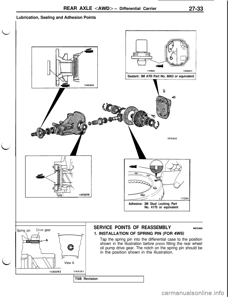
Lubrication, Sealing and Adhesion Points
L
11lwO.llFOO11
Sealant: 3M AID Part No. 8663 or equivalentllFO032
Adhesive: 3M Stud Locking Part
No. 4170 or equivalent
Spring pinDjive gear
View A
ilA0262llA0261
SERVICE POINTS OF REASSEMBLYM27UBG
1. INSTALLATION OF SPRING PIN (FOR
4WS)
Tap the spring pin into the differential case to the position
shown in the illustration before
press fitting the rear wheel
oil pump drive gear. The notch on the spring pin should bein the position shown in the illustration.
TSB Revision
Page 630 of 1146
27-34
REAR AXLE
YYW!-01
I1 11AOlOl
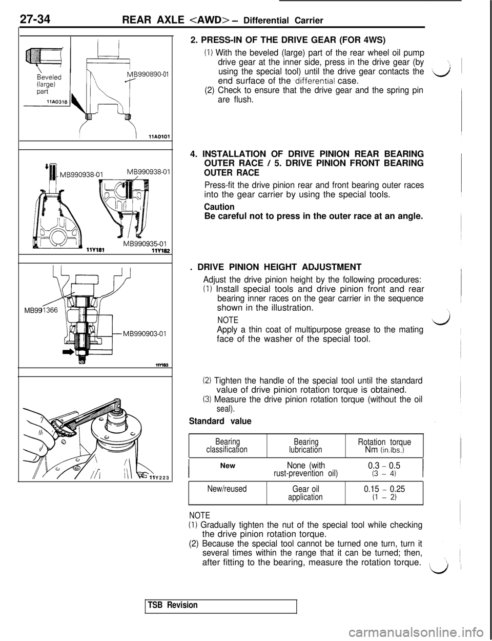
MB99Y2232. PRESS-IN OF THE DRIVE GEAR (FOR 4WS)
(1) With the beveled (large) part of the rear wheel oil pump
drive gear at the inner side, press in the drive gear (by
using the special tool) until the drive gear contacts theend surface of the
.differential case.
(2) Check to ensure that the drive gear and the spring pin
are flush.4. INSTALLATION OF DRIVE PINION REAR BEARING
OUTER RACE
/ 5. DRIVE PINION FRONT BEARING
OUTER RACE
Press-fit the drive pinion rear and front bearing outer racesinto the gear carrier by using the special tools.
CautionBe careful not to press in the outer race at an angle.
. DRIVE PINION HEIGHT ADJUSTMENT
Adjust the drive pinion height by the following procedures:
(1) Install special tools and drive pinion front and rear
bearing inner races on the gear carrier in the sequenceshown in the illustration.
NOTE
Apply a thin coat of multipurpose grease to the matingface of the washer of the special tool.
(2) Tighten the handle of the special tool until the standardvalue of drive pinion rotation torque is obtained.
(3) Measure the drive pinion rotation torque (without the oil
seal).
Standard value
Bearing
classificationBearing
lubricationRotation torqueNm (in.lbs.1
INew
None (with0.3 - 0.5rust-prevention oil)(3 - 4)I
New/reused
NOTEGear oil
application0.15 - 0.25
(1 - 2)
(1) Gradually tighten the nut of the special tool while checkingthe drive pinion rotation torque.
(2) Because the special tool cannot be turned one turn, turn it
several times within the range that it can be turned; then,after fitting to the bearing, measure the rotation torque.
L/1 1
TSB Revision