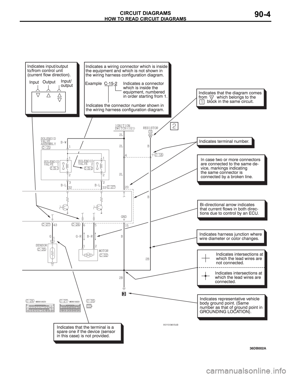
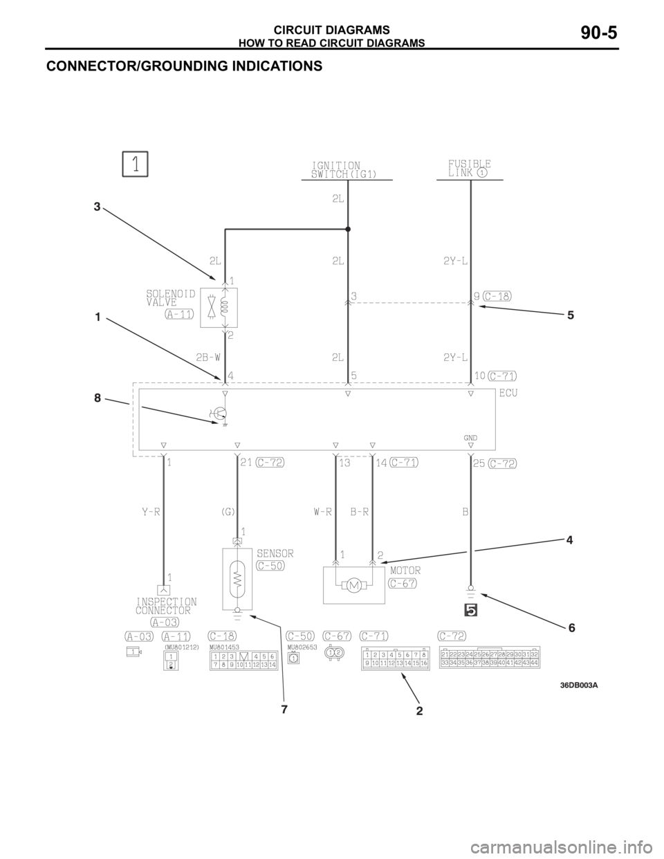
HOW TO READ CIRCUIT DIAGRAMS
CIRCUIT DIAGRAMS90-6
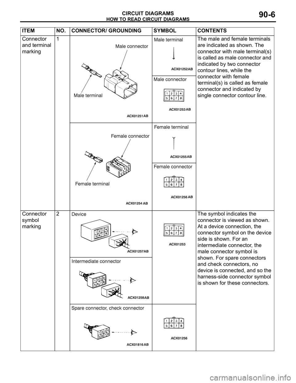
ITEM NO. CONNECTOR/ GROUNDING SYMBOL CONTENTS
Connector
and terminal
marking1 The male and female terminals
are indicated as shown. The
connector with male terminal(s)
is called as male connector and
indicated by two connector
contour lines, while the
connector with female
terminal(s) is called as female
connector and indicated by
single connector contour line.
Connector
symbol
marking2 The symbol indicates the
connector is viewed as shown.
At a device connection, the
connector symbol on the device
side is shown. For an
intermediate connector, the
male connector symbol is
shown. For spare connectors
and check connectors, no
device is connected, and so the
harness-side connector symbol
is shown for these connectors.
HOW TO READ CIRCUIT DIAGRAMS
CIRCUIT DIAGRAMS90-7
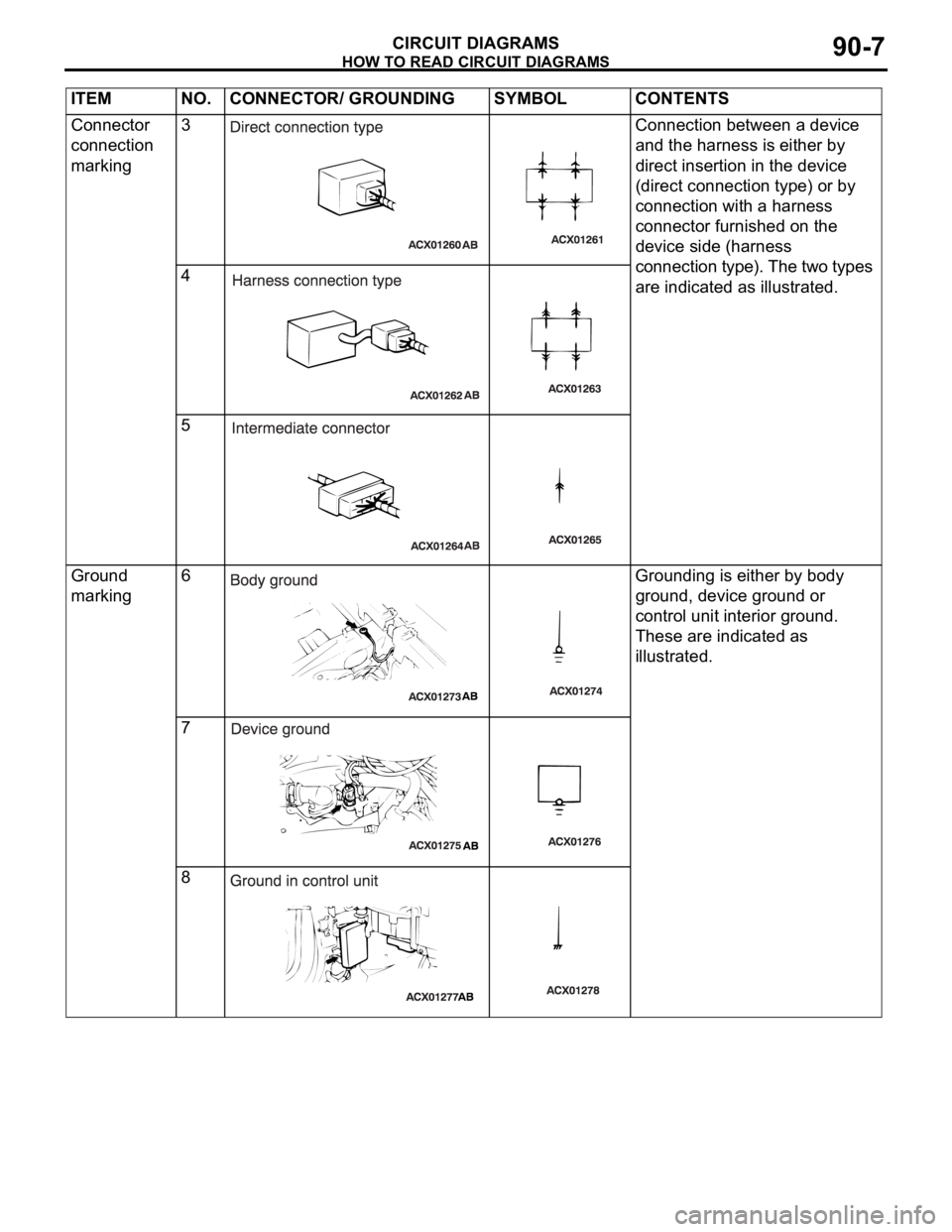
Connector
connection
marking3 Connection between a device
and the harness is either by
direct insertion in the device
(direct connection type) or by
connection with a harness
connector furnished on the
device side (harness
connection type). The two types
are indicated as illustrated. 4
5
Ground
marking6 Grounding is either by body
ground, device ground or
control unit interior ground.
These are indicated as
illustrated.
7
8 ITEM NO. CONNECTOR/ GROUNDING SYMBOL CONTENTS
HOW TO READ CIRCUIT DIAGRAMS
CIRCUIT DIAGRAMS90-8
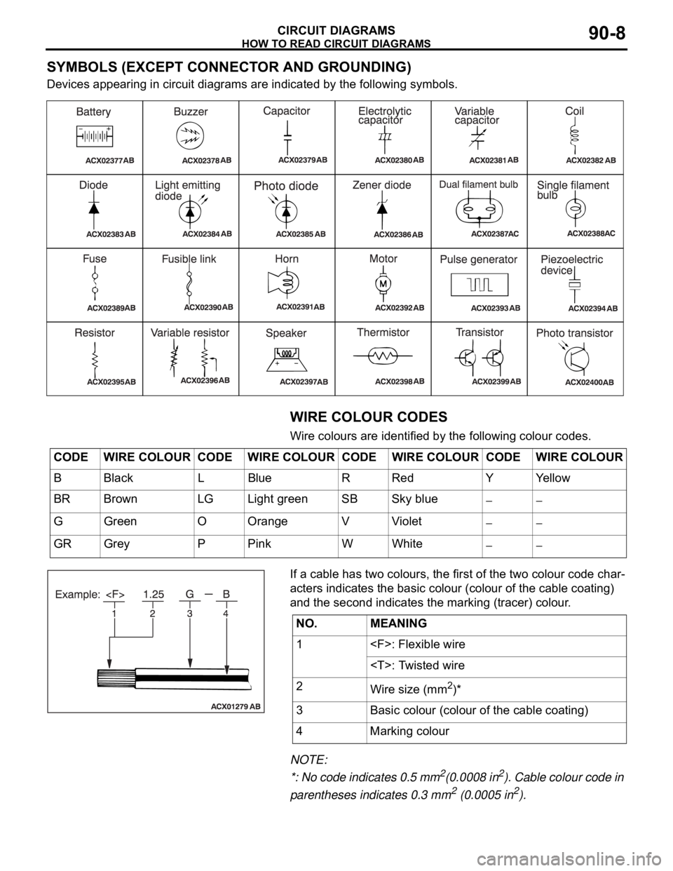
SYMBOLS (EXCEPT CONNECTOR AND GROUNDING)
Devices appearing in circuit diagrams are indicated by the following symbols.
WIRE COLOUR CODES
Wire colours are identified by the following colour codes.
If a cable has two colours, the first of the two colour code char-
acters indicates the basic colour (colour of the cable coating)
and the second indicates the marking (tracer) colour.
NOTE:
*: No code indicates 0.5 mm
2(0.0008 in2). Cable colour code in
parentheses indicates 0.3 mm
2 (0.0005 in2).
CODE WIRE COLOUR CODE WIRE COLOUR CODE WIRE COLOUR CODE WIRE COLOUR
B Black L Blue R Red Y Yellow
BR Brown LG Light green SB Sky blue
G Green O Orange V Violet
GR Grey P Pink W White
NO. MEANING
1 : Flexible wire
: Twisted wire
2
Wire size (mm
2)*
3 Basic colour (colour of the cable coating)
4 Marking colour
CENTRALISED JUNCTION
CIRCUIT DIAGRAMS90-12
CENTRALISED JUNCTIONM1901000301013
FUSIBLE LINK AND FUSE
ENGINE COMPARTMENT
NO. POWER SUPPLY
CIRCUITNAME RATED
CAPACITY (A)HOUSING
COLOURLOAD CIRCUIT
1 Battery/Alternator
(Fusible link No.27)Fusible
link80 Black Fuse Nos.5, 6, 9 and 10 (in junction
block) circuit
2 50 Blue Radiator fan motor
3 30 Pink ABS-ECU and ABS/TCL-ECU (motor
power supply)
4 40 Green Ignition switch circuit
5 40 Green Fuse Nos.3 and 4 (in junction block
circuit), front power window regulator
motor, power seat assembly, power
window main switch and rear power
window regulator motor
6 Fuse 15 Blue Fog lamp and fog lamp relay
720Yellow
8 15 Red Horn (High), horn (Low) and horn
relay
9 20 Yellow Camshaft position sensor, crankshaft
position sensor, engine oil control
valve, evaporative emission purge
solenoid, evaporative emission
ventilation solenoid, heated oxygen
sensor,ETACS-ECU, injector, mass
airflow sensor, MPI relay, Engine
ECU, A/T ECU, throttle actuator
control motor relay and fan control
relay
10 10 Red A/C compressor assembly and
A/C-ECU
11 15 Blue ABS-ECU, ABS/TCL-ECU,
high-mounted stoplamp, Engine ECU
and rear combination lamp
12
13 7.5 Brown
Alternator
14 10 Red ETACS-ECU, Hazard lamps
15 20 Yellow A/T control solenoid valve and Engine
ECU
16 Front-ECU
(Headlamp relay:
High)15 Blue Headlamp (RH) and headlamp (High:
RH)
17 15 Blue Headlamp (LH) and headlamp (High:
LH)
18 Front-ECU (Field
effect transistor for
headlamp: Low)10 Red Headlamp (RH) and headlamp (Low:
RH)
CENTRALISED JUNCTION
CIRCUIT DIAGRAMS90-13
19 Front-ECU (Field
effect transistor for
headlamp: Low)Fuse 10 Red Headlamp (LH) and headlamp (Low:
LH)
20 Front-ECU (Taillamp
relay)7.5 Brown A/C-ECU, A/T selector lever position
illumination lamp, combination meter,
fog lamp switch, headlamp (RH),
glove box lamp, hazard warning lamp
switch, multi-center display unit,
radio, CD player, rear combination
lamp (RH), rheostat and TCL switch
21 7.5 Brown Headlamp (LH), license plate lamp
and rear combination lamp (LH)
22 Battery/Alternator
(Fusible link No.27)15 Blue A/C-ECU, column switch,
combination meter, ETACS-ECU,
front-ECU, key reminder switch, multi-
center display unit, radio, CD player,
and vanity mirror lamp
23 Ignition switch (ACC) 10 Red A/C-ECU, accessory socket relay,
ETACS-ECU, multi-center display
unit, radio, CD player.
24 Battery/Alternator
(Fusible link No.27)15 Blue Fuel pump module
25 Ignition switch (ACC) 30 Green Front-ECU and windshield wiper
motor
26 Battery/Alternator
(Fusible link No.27)Fusible
link20 Light blue Anti-lock braking system(solenoid
valve)
27
Alternator120
Battery, front-ECU, fusible link Nos.1,
2, 3, 4, 5 and 26 and fuse Nos.6, 7, 8,
9, 10, 11, 13, 14, 15, 22 and 24 (in
relay box) NO. POWER SUPPLY
CIRCUITNAME RATED
CAPACITY (A)HOUSING
COLOURLOAD CIRCUIT
