MITSUBISHI COLT 2006 Service Repair Manual
Manufacturer: MITSUBISHI, Model Year: 2006, Model line: COLT, Model: MITSUBISHI COLT 2006Pages: 364, PDF Size: 11.65 MB
Page 241 of 364
ELECTRICAL POWER STEERING
POWER STEERING37-8
ELECTRICAL PARTS AND FUNCTIONS
Parts nameDescription about function
SensorVehicle speed sensor (ABS-ECU)Sends the vehicle speed signal to the electric power
steering-ECU.
Torque sensorDetects a steering force, converts it into the voltage signal,
and then sends the signal to the electric power
steering-ECU.
ActuatorMotorGenerates assist torque by the steering operation to the
steering gear using the signals sent from the electric power
steering-ECU.
Electric power steering warning
lampWarns a driver of the system malfunction using the signal
sent from the electric power steering-ECU.
Electric power steering-ECUControl the actuator (motor) based on the signal sent from
sensor.
Controls the self-diagnostic fu nction and fail-safe function.
Controls diagnostic function (Compatible with M.U.T.-III).
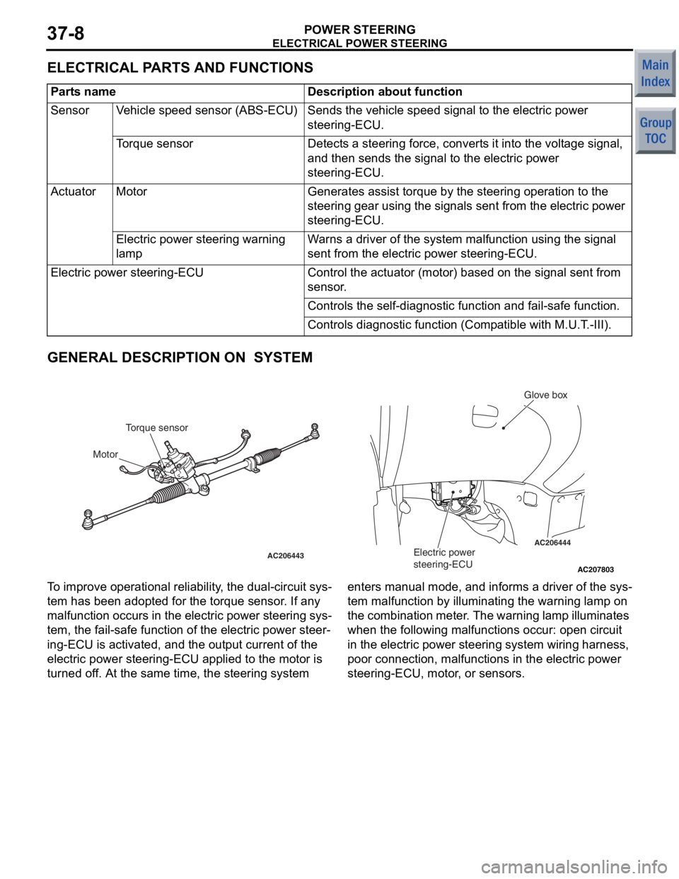
GENERAL DESCRIPTION ON SYSTEM
AC207803
AC206444
AC206443
AB
Electric power
steering-ECU
Glove box
Torque sensor
Motor
T o improve opera t iona l reliabi lity , th e dual-circuit sys-
tem ha s be en ad opted f o r the t o rque sensor . If a n y
malfunct
i on occurs in the electric power st eering sys
-
tem, the fail-sa f e fun c tio n of th e ele c tric power steer-
ing-ECU is activated, and the ou tput current of the
electric power steerin
g-ECU a pplied to the motor is
turned o
f f. At th e sa me time, the steerin g syste m enters man ual mode, and informs a dr iver of the sys
-
tem malfu
n ction by illuminating th e warnin g lamp on
the
comb in at io n me te r . Th e warn in g la mp il lu min a te s
wh
en the following malfu n ct ions occur: ope n circuit
in the
e l ectric power stee ring system wiring harness,
poor connectio
n , ma lfunction s in the e l ectric power
steering-ECU, mo
tor , or sensors.
Page 242 of 364
ELECTRICAL POWER STEERING
POWER STEERING37-9
STEERING GEAR
M2370003000239
AC208175
AC208174AC206443AC
NeutralSub
Torque sensor
Steered to leftMain
Steered to right
Output voltage (V)
Torque sensor characteristic chart
52.5
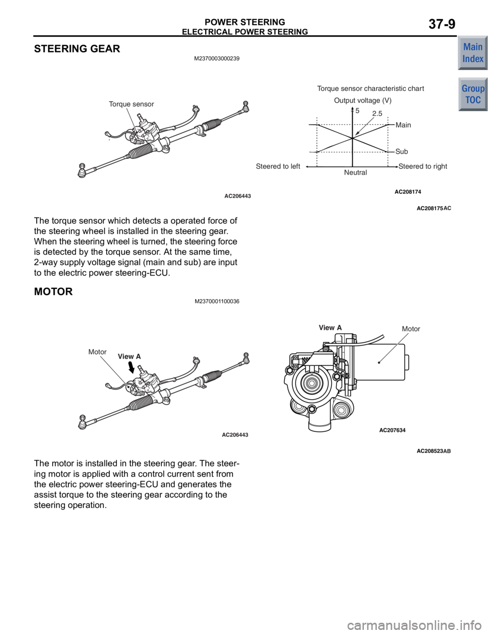
The torqu e sensor which detect s a opera t ed force of
the steerin
g wheel is inst alled in the stee ring g ear .
Whe
n th e st eer in g whe e l is tu rn ed , t h e ste e ring f o rce
is d
e tected by the to rque sensor . At the same time,
2-way supp
ly volt a ge signa l (main and sub ) are input
to the e
l ectric power steerin g-ECU.
MOT O RM237000 1 1 0003 6
AC208523
AC206443
AC207634
AB
View AMotor
Motor
View A
The mot
o r is inst alled in th e steering gea r . The ste e r-
ing motor is applied with a con t rol current sent from
the electric po
we r stee ring-ECU and genera t es t he
assist
torque to the steering ge ar according to the
steering op
eratio n.
Page 243 of 364
ELECTRICAL POWER STEERING
POWER STEERING37-10
ELECTRIC POWER STEERING-ECU
M2370000800106
AC207827AB
Glove box
Electric power
steering-ECU
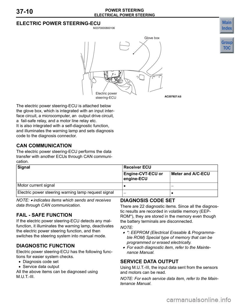
The electric powe r stee ring-ECU is att a ch ed below
the glove
box, wh ich is integ r ated wit h an input inter
-
face circu i t, a microco m p u ter , an outp u t d r ive circuit,
a fail-sa
f e rela y , and a mot o r line relay et c.
It is also integrated with a self-diag nostic fu nction,
and illuminate
s the warn ing lamp an d set s d i agno sis
code
to the diagn osis connector .
CAN COMMUNICATION
The electric powe r stee ring-ECU perfo rms the da t a
transf
e r with a nother ECUs through CAN communi
-
cation.
SignalReceiver ECU
Engine-CVT-ECU or
engine-ECUMeter and A/C-ECU
Motor current signal•−
Electric power steering warning lamp request signal−•
NOTE: • ind i ca tes items which sends and re ceives
dat
a throu gh CAN communicat i on.
FA IL - SAFE FUNCTION
If the e l ectric power st eering - ECU de tect s any mal-
functi on, it illuminat es th e warnin g lamp, de activate s
the electric po
we r stee ring f unct i on, a nd the n
switches
the steerin g system in to ma nual mode .
DIAGNOSTIC FUNCTION
Electric po wer ste e ring -ECU has the following fu nc-
tions for easie r system ch ecks.
•Diagnosis code set
•Service dat a outp u t
All the above ite m s can be diagnosed using
M.U.T
. -III.
DIAGNOSIS CODE SET
There a r e 22 d i agno stic ite m s. Since all the d i agn os-
tic result s are recorded in volatile memory (EEP-
ROM*), they a r e sto r ed in the memo ry even th ough
the bat
tery t e rminals are d i sconne cted.
NOTE: .
•*: EEPROM (E lectrical Erasable & Programma-
ble ROM) Special ty pe o f me mory that can b e
prog
rammed or erase d ele c trically .
•For each diag nostic item, refer to the Mainte-
nance Manua l.
SERV ICE DA T A OUTPUT
Usin g M. U. T . -II I , t h e i n p u t d a t a s e n t f r om t h e se ns ors
and motors can
be rea d .
NOTE: For e a ch service dat a it em, re fer to th e Ma in-
tenance Manual.
Page 244 of 364
ELECTRICAL POWER STEERING
POWER STEERING37-11
OPERATION
M2370000700110
IGNITION SWITCH ON
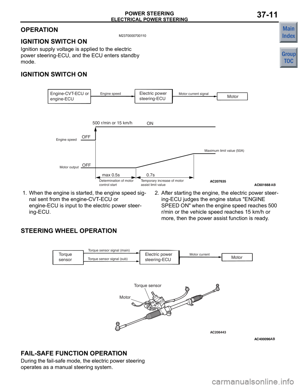
Ignition supply voltage is applied to the electric
power steering-ECU, and the ECU enters standby
mode.
IGNITION SWITCH ON
AC601668AC207635 AB
Electric power
steering-ECU
OFF
OFF MotorMotor current signal
Maximum limit value (50A)
Engine speed
Engine speed
ON
500 r/min or 15 km/h
max 0.5s 0.7s
Motor output Determination of motor
control start Temporary increase of motor
assist limit value
Engine-CVT-ECU or
engine-ECU
1.
Whe n th e e ngine is st arted, the en gine sp eed sig-
nal sent from the en gine -CVT -ECU or
eng
ine-ECU is inp u t to th e ele c tric power steer
-
ing-ECU.
2. Af ter st a r ting the engine, the electric power ste e r-
ing-ECU judges the engin e st atu s "ENGINE
SPEED ON"
when the engine speed reaches 500
r/min or
the vehicle speed reaches 1 5 km/h or
more, the
n the p o wer assist functio n is ready .
STEERING WHEEL OPERAT ION
AC400096
AC206443AB
Electric power
steering-ECU
Torque
sensor
Torque sensor
Motor Motor
Motor current
Torque sensor signal (main)
Torque sensor signal (sub)
F A IL- S AFE FUNCTION OPERA T ION
Duri ng t h e f a il -s af e m o d e , t h e el ect r ic powe r st ee rin g
operate
s as a manual ste e ring system.
Page 245 of 364
GROUP 36
PARKING BRAKES
CONTENTS
GENERAL INFORMATION . . . . . . . .36-2
STRUCTURAL DESCRIPTION
OPERATIONAL DESCRIPTION
Page 246 of 364
GENERAL INFORMATION
PARKING BRAKES36-2
GENERAL INFORMATION
M2360000100656
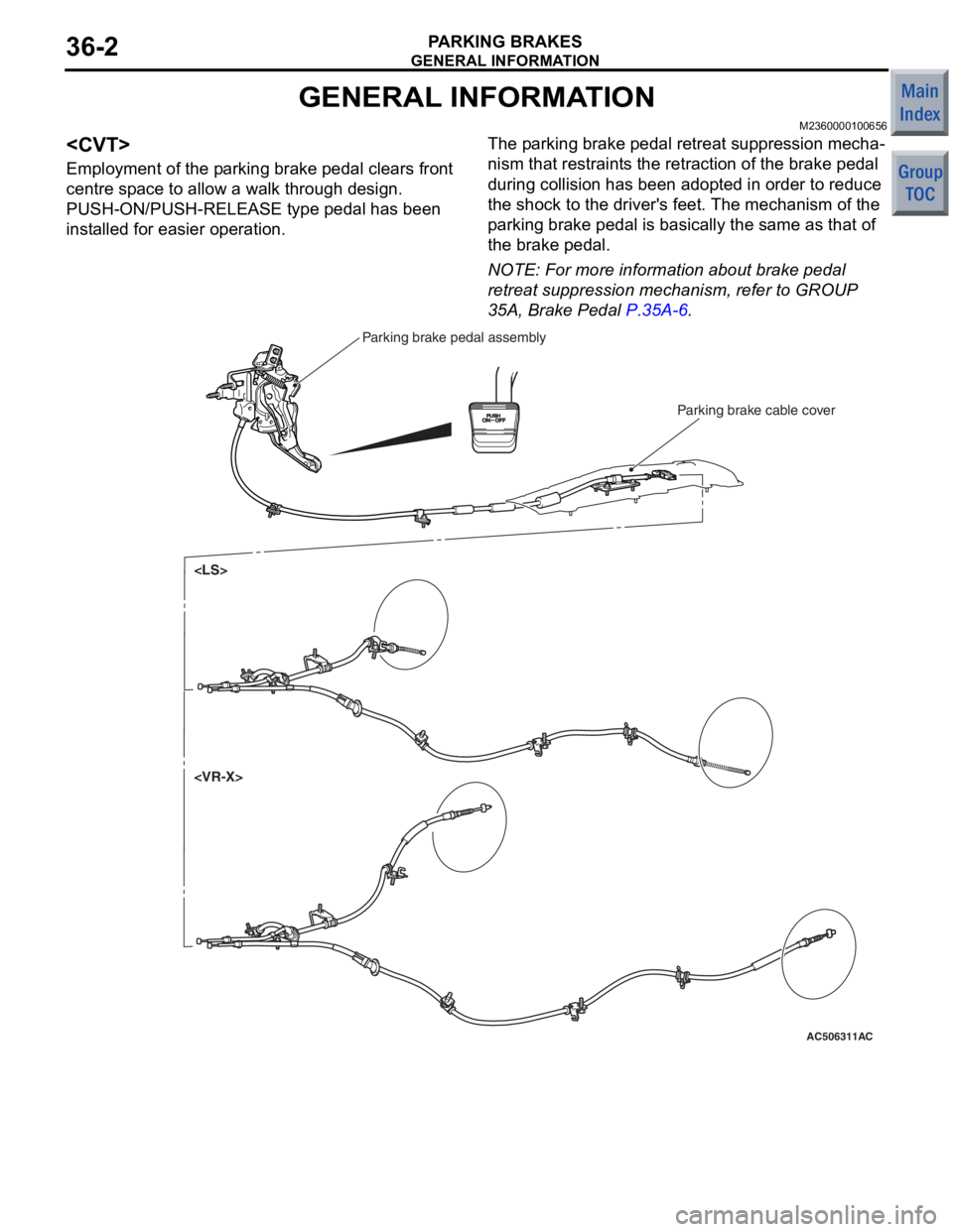
Employment of the parking brake pedal clears front
centre space to allow a walk through design.
PUSH-ON/PUSH-RELEASE type pedal has been
installed for easier operation.
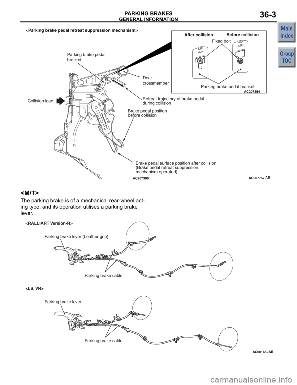
The parking brake pedal retreat suppression mecha-
nism that restraints the retraction of the brake pedal
during collision has been adopted in order to reduce
the shock to the driver's feet. The mechanism of the
parking brake pedal is basically the same as that of
the brake pedal.
NOTE: For more information about brake pedal
retreat suppression mechanism, refer to GROUP
35A, Brake Pedal
P.35A-6.
AC506311AC
Parking brake cable cover
Parking brake pedal assembly
Page 247 of 364
AC207757
AC207354
AC207360AB
Fixed boltBefore collision
After collision
Parking brake pedal bracket
Deck
crossmember
Retreat trajectory of brake pedal
during collision
Brake pedal position
before collision
Brake pedal surface position after collision
(Brake pedal retreat suppression
mechanism operated)
Parking brake pedal
bracket
Collision load
GENERAL INFORMA
T ION
PA R K ING BR AKES36-3
The pa rking b r ake is o f a me chan ica l rea r-wh eel a c t-
ing type, and it s operat ion u t ilises a p a rking b r ake
leve
r .
AC601652
Parking brake lever
Parking brake cable
Parking brake lever (Leather grip)Parking brake cable
AB
Page 248 of 364
STRUCTURAL DESCRIPTION
PARKING BRAKES36-4
STRUCTURAL DESCRIPTION
M2360000200192
AC207357AB
PawlSector
Release lever
Pawl return spring
Return spring
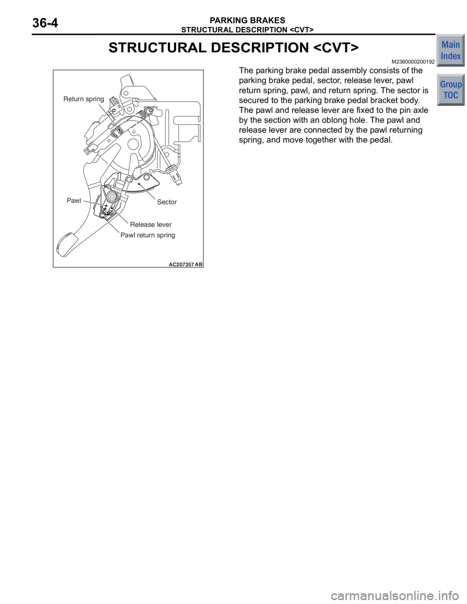
The pa rking b r ake pedal assemb ly consist s of the
p
a r k ing brake peda l, secto r , rele ase leve r , p a wl
return sprin
g , p a wl, an d return spring. Th e sector is
secured to
the p a rking b r ake pedal bracket b ody .
The p
a wl a nd release lever are f i xe d to the pin axle
by th
e sectio n with a n oblong ho le. Th e p a wl and
release lever
are co nnected by the p a wl returning
spring, an
d move tog e ther with the pedal.
Page 249 of 364
OPERATIONAL DESCRIPTION
PARKING BRAKES36-5
OPERATIONAL DESCRIPTION
M2360000300207
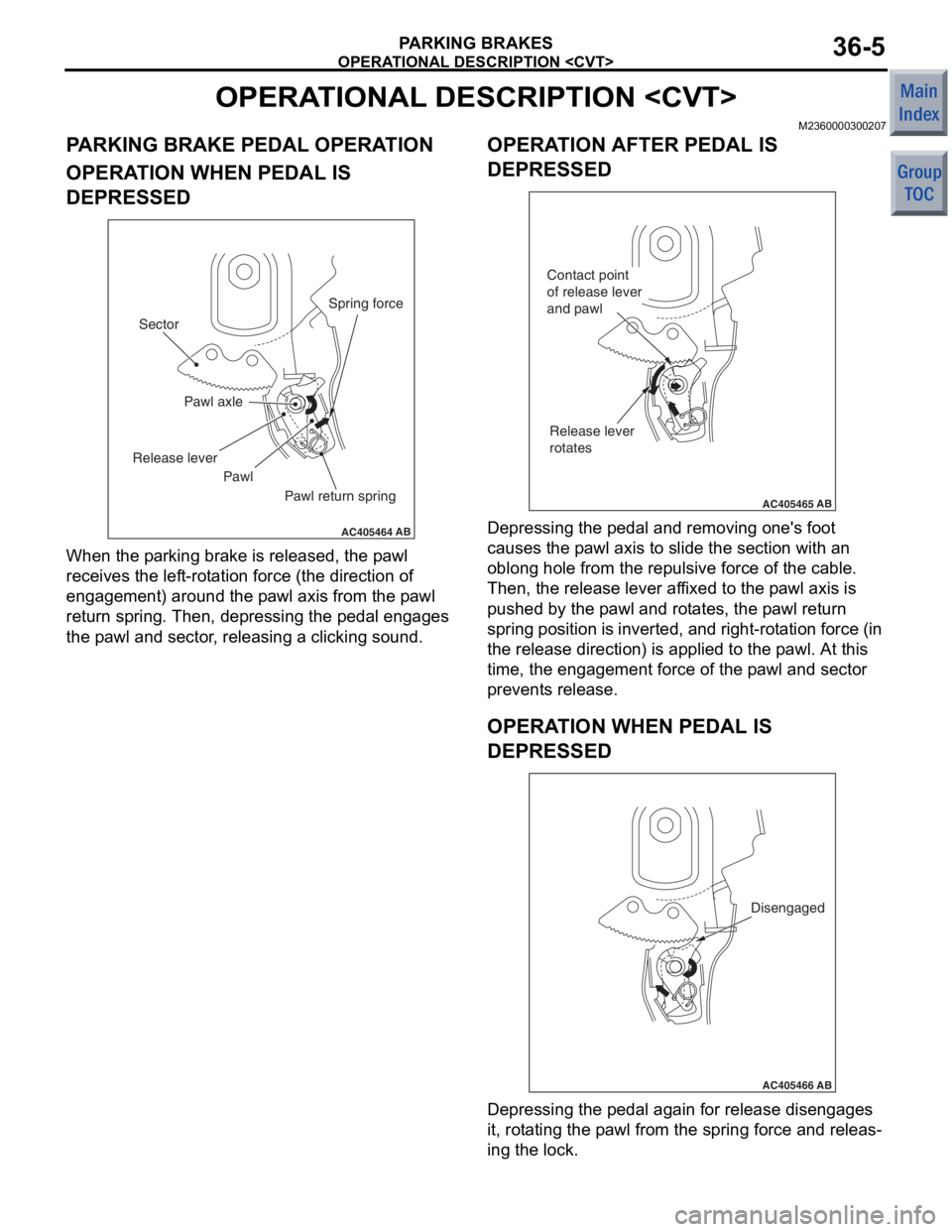
PARKING BRAKE PEDAL OPERATION
OPERATION WHEN PEDAL IS
DEPRESSED
AC405464
Pawl axle
AB
Sector
Release lever
Pawl Pawl return springSpring force
When th
e p a rking bra k e is released, the p a wl
receives the lef
t -rot a tion force (the d i rection o f
engage
ment ) around the p a wl axis from the p a wl
return sprin
g . Then , depre ssing th e peda l eng ages
the p
a wl an d se ctor , relea s ing a clickin g so und.
OPERAT ION AFTER PEDAL IS
DEPRESSED
AC405465
Contact point
of release lever
and pawl
Release lever
rotates
AB
De pressing the pe dal a nd removing on e's fo ot
causes
the p a wl axis to slid e the sect ion with an
oblon
g hole from the re pulsive force of th e cab l e.
Then, t
he release lever af fixe d to th e p a wl axis is
push
ed by the p a wl and rot a te s, the p a wl return
spring position
is inverted, an d r i ght-ro t a t i on force (in
the release dire
ctio n) is appl ied to the p a wl. At this
time
, the e ngage ment force of the p a wl and sect or
preve
n t s release .
OPERAT ION W H EN PEDAL IS
DEPRESSED
AC405466AB
Disengaged
Depressing the pe dal a gain for release disengag es
it, rot
a ting the p a wl from the sprin g force and releas
-
ing the lock.
Page 250 of 364
OPERATIONAL DESCRIPTION
PARKING BRAKES36-6
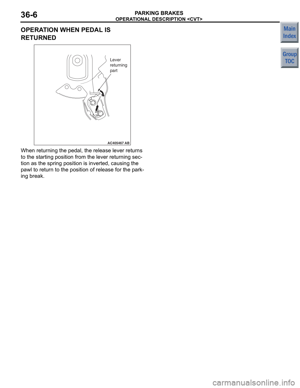
OPERATION WHEN PEDAL IS
RETURNED
AC405467
Lever
returning
part
AB
When returnin g the p edal, the release lever ret u rns
to the st
arting position from the lever returning se c
-
tion as the spring po sition is inverte d , ca using the
p
a wl to retu rn to th e positio n of release for th e p a rk
-
ing br eak.