MITSUBISHI COLT 2006 Service Repair Manual
Manufacturer: MITSUBISHI, Model Year: 2006, Model line: COLT, Model: MITSUBISHI COLT 2006Pages: 364, PDF Size: 11.65 MB
Page 281 of 364
ECU FUNCTIONS AND CONTROLS IN THE SWS
SMART WIRING SYSTEM (SWS)54B-15
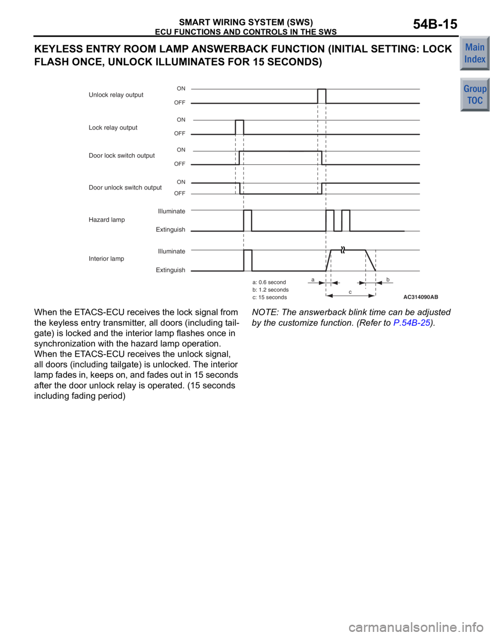
KEYLESS ENTRY ROOM LAMP ANSWERBACK FUNCTION (INITIAL SETTING: LOCK
FLASH ONCE, UNLOCK ILLUMI NATES FOR 15 SECONDS)
AC314090
OFFON
ON
OFF
Illuminate
Extinguish
Lock relay output
OFF
ONDoor unlock switch output
OFFON
Door lock switch output Unlock relay output
Hazard lamp
Illuminate
Extinguish
Interior lamp
AB
ab
c
a: 0.6 second
b: 1.2 seconds
c: 15 seconds
When the
ET ACS-ECU receives t he lock signa l from
the keyless entry transmit
t er , all doo rs (includin g t a il
-
gate) is locked and the interior lamp flashe s once in
syn
chron i za tion with the haza r d lamp op eratio n.
When th
e ET ACS-ECU receives the u n lock sign al,
all d
oors (including t a ilgate) is u n locked . The interior
lamp fades in, keep
s on, and fades out in 15 seconds
af
te r the d oor unlock rela y is ope rated. (15 se cond s
including fad
i ng p e riod)
NOTE: The answerb ack blink t i me can be adjuste d
by th
e customize function. (Re f er to
P.54B-25).
Page 282 of 364
ECU FUNCTIONS AND CONTROLS IN THE SWS
SMART WIRING SYSTEM (SWS)54B-16
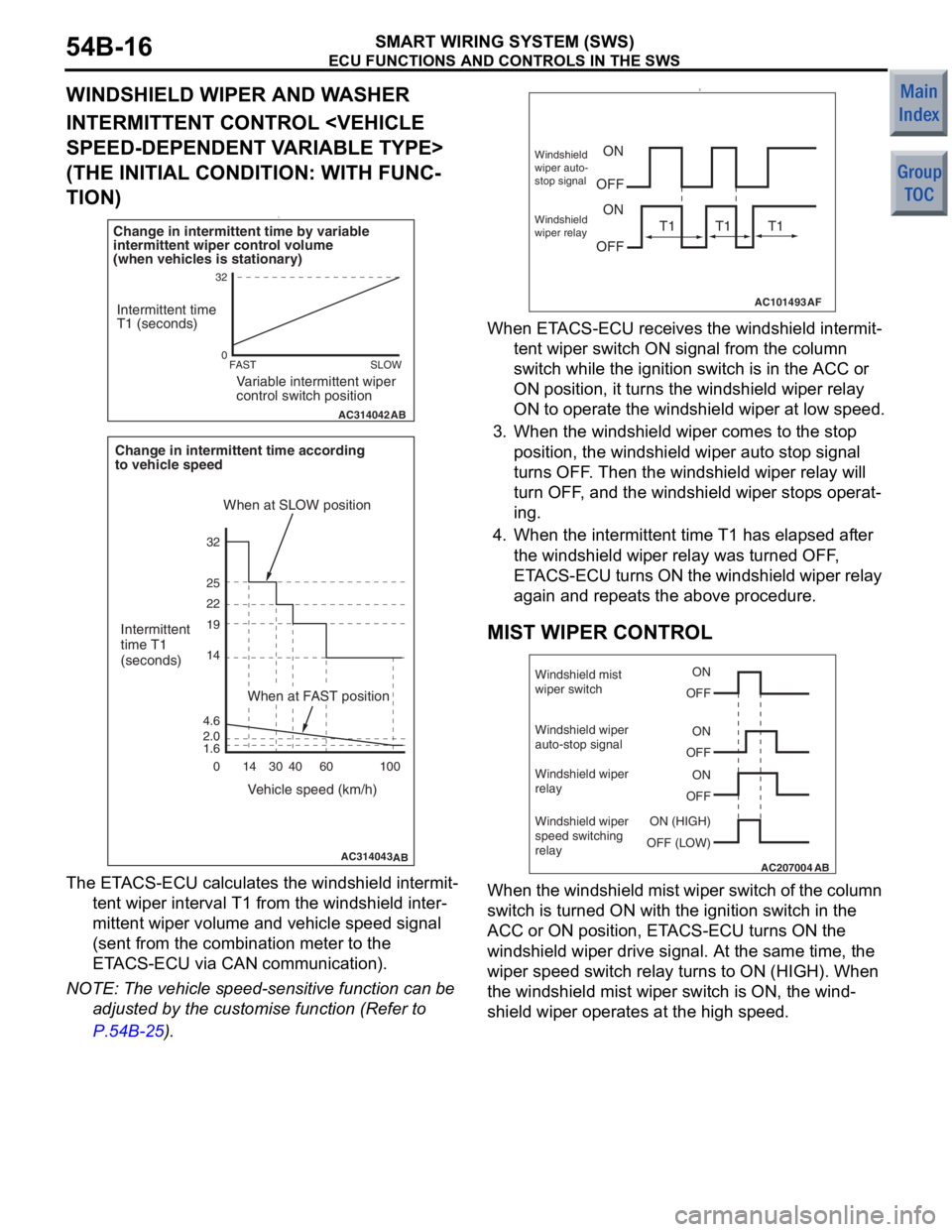
WINDSHIELD WIPER AND WASHER
INTERMITTENT CONTROL
(THE INITIAL CONDITION: WITH FUNC
-
TION)1.
AC314042AB
FAST SLOW
0
32
Variable intermittent wiper
control switch position
Intermittent time
T1 (seconds)
Change in intermittent time by variable
intermittent wiper control volume
(when vehicles is stationary)
AC314043
Intermittent
time T1
(seconds)
Vehicle speed (km/h)
When at SLOW position
Change in intermittent time according
to vehicle speed
0 100
AB
60
40
30
14
14 19 22 25 32
4.6
1.6
2.0
When at FAST position
The ET ACS-ECU calculates the win d shield intermit-
tent wiper interval T1 from the wind shield inter-
mittent wiper volume an d veh i cle speed sign al
(sent from the
combina t ion meter to the
ET
A C S-ECU via CA N communication).
NOTE: The vehicle spe ed-sensitive function can be
adjuste d by the custo m ise fun c tion (Refer to
P.54B-25).
2.
AC101493AF
ON
OFF ON
OFFWindshield
wiper auto-
stop signal
Windshield
wiper relay
T1 T1 T1
When ET ACS-ECU receives th e windshie l d intermit-
tent wiper switch ON signa l from the colu mn
switch while t
he ig nition switch is in the ACC or
ON
position, it tu rns th e windshie l d wipe r rela y
ON
to opera t e the windshield wiper at low speed .
3.Whe n the windsh i eld wiper comes to the stop
position, th e windshie l d wipe r auto stop sig nal
turn s OFF . T hen the windshield wipe r relay will
turn OFF , and the win d shield wiper stop s op erat
-
ing.
4. Whe n the intermitten t time T1 h a s e l ap sed af ter
the windshield wiper relay was t u rned OFF ,
ET A C S-ECU turns ON the windshield wiper relay
aga in an d repe at s the a bove procedure.
MIST WIPER CONTROL
AC207004AB
ON
OFF
ON
OFF
ON
OFF
ON (HIGH)
Windshield mist
wiper switch
Windshield wiper
auto-stop signal
Windshield wiper
relay
Windshield wiper
speed switching
relay
OFF (LOW)
When
the windshield mist wipe r switch of t he column
switch is turne
d ON with the ignition switch in th e
ACC or ON positio
n, ET ACS-ECU turns ON the
windshield wiper
drive signal . At the same time, the
wiper speed switch rela
y turn s to ON (HIGH). W hen
the wind
shield mist wiper switch is ON, th e wind
-
shield wipe r ope rates at the high spee d.
Page 283 of 364
ECU FUNCTIONS AND CONTROLS IN THE SWS
SMART WIRING SYSTEM (SWS)54B-17
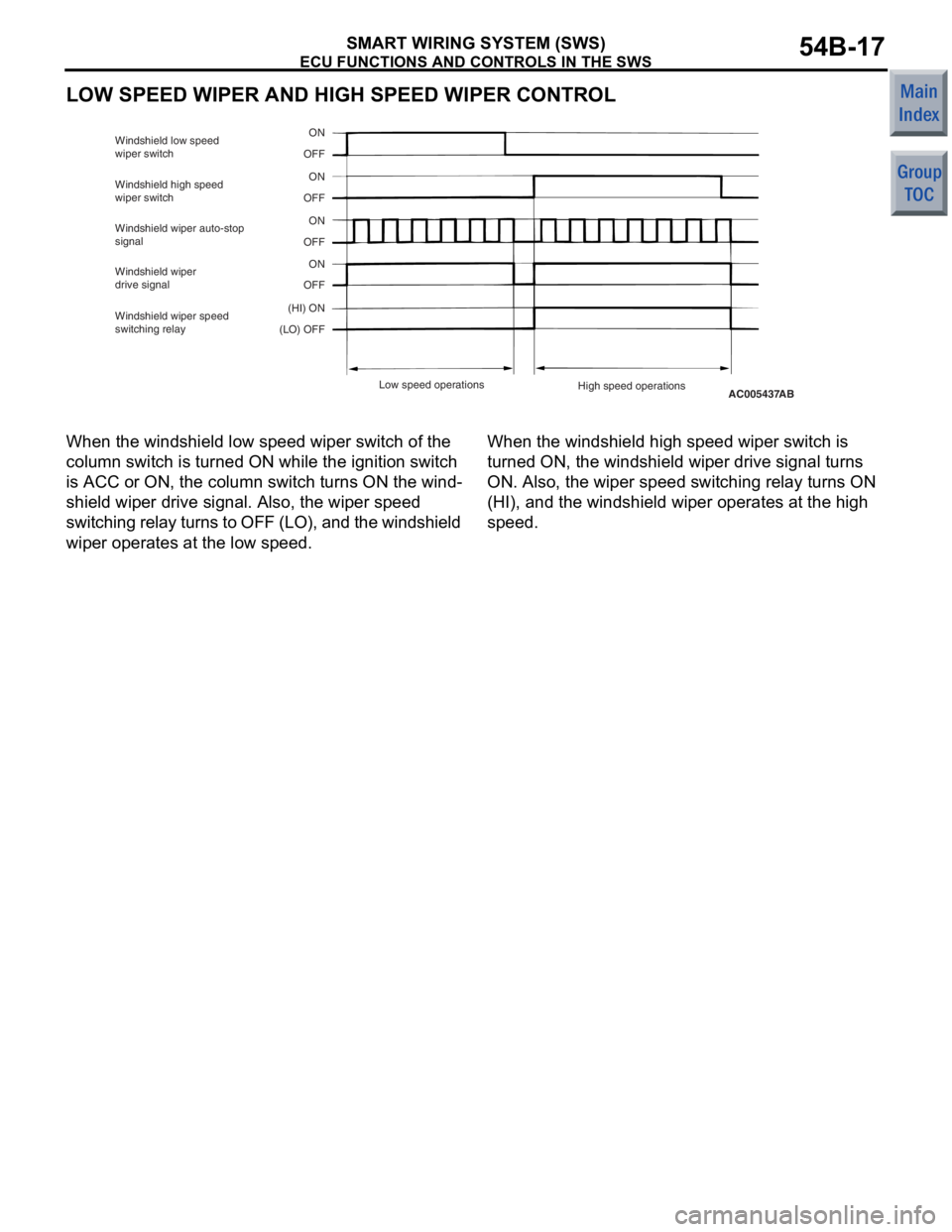
LOW SPEED WIPER AND HIGH SPEED WIPER CONTROL
AC005437AB
ON
OFF
ON
OFF
ON
OFF
(HI) ON
Windshield low speed
wiper switch
Windshield high speed
wiper switch
Windshield wiper auto-stop
signal
ON
OFF
Windshield wiper
drive signal
Windshield wiper speed
switching relay
(LO) OFF
Low speed operations High speed operations
When the windshie l d low spee d wiper switch of th e
colu
mn switch is turned ON while the ignition switch
is ACC or ON, the colu
mn switch turns ON the wind
-
shield wip e r drive signa l. Also, the wiper speed
switching relay turns to OFF (LO), and the windshield
wiper op
erates at the low speed.
When the windshie l d high speed wiper switch is
turned
ON, the windshield wiper drive signal turns
ON. Also, the
wiper speed switching relay turn s ON
(HI),
and th e windshie l d wip e r opera t es a t the h i gh
spee
d.
Page 284 of 364
ECU FUNCTIONS AND CONTROLS IN THE SWS
SMART WIRING SYSTEM (SWS)54B-18
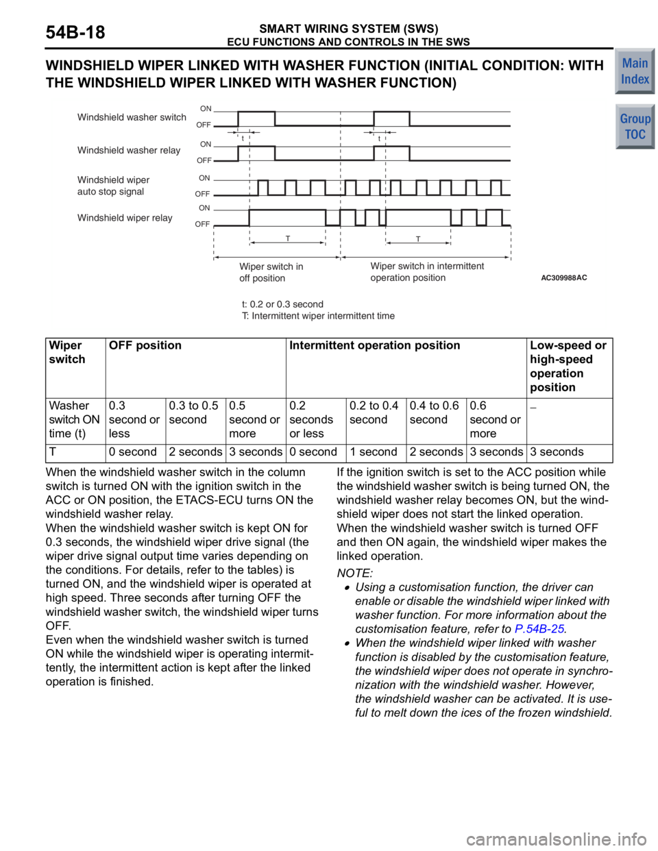
WINDSHIELD WIPER LINKED WITH WASHER FUNCTION (INITIAL CONDITION: WITH
THE WINDSHIELD WIPER LINKED WITH WASHER FUNCTION)
AC309988AC
t
t
T T
ON
OFF
ON
OFF
ON
OFF ON
OFF
Windshield wiper
auto stop signal Windshield washer relay Windshield washer switch
Windshield wiper relay
Wiper switch in
off positionWiper switch in intermittent
operation position
t: 0.2 or 0.3 second
T: Intermittent wiper intermittent time
Wiper
switchOFF positionIntermittent operation positionLow-speed or
high-speed
operation
position
Washer
switch ON
time (t)0.3
second or
less0.3 to 0.5
second0.5
second or
more0.2
seconds
or less0.2 to 0.4
second0.4 to 0.6
second0.6
second or
more−
T0 second2 seconds3 seconds0 second1 second2 seconds3 seconds3 seconds
When th e windshie l d washer switch in the column
switch is turned
ON with the ignition switch in th e
ACC or ON positio
n, the ET ACS-ECU turn s ON the
windsh
i eld washe r rela y .
When the windshie l d washer switch is kept ON for
0.3 secon
d s, th e windshie l d wip e r drive signa l (the
wiper drive sign
al ou tput time varie s de pending on
the condit
i ons. For d e t a ils, refer t o the t ables) is
turned ON, and
the win d shield wiper is ope rated a t
high
spee d. Three seconds af ter turn ing OFF th e
windshie
l d wa sh er switch, th e win d sh ield wip e r tu rns
OFF
.
Even when the win d shield wa sher switch is turne d
ON while the windsh
i eld wiper is o perating in termit
-
tently, the intermittent action is ke pt af ter th e linked
operation is finished.
If the igniti on switch is se t to the ACC position while
t
h e wind shie ld wa sher swit ch i s be ing tu rn ed ON, t he
windshield washe
r rela y becomes ON, but th e wind
-
shield wipe r doe s not st art the lin ked operation.
When th
e windshie l d washer switch is t u rned OFF
and the
n ON a gain , the win d shield wiper make s the
linked o
peration.
NOTE: .
•Using a cust omisation fun c tion, the driver ca n
en
ab le or dis abl e th e wi nd shi e ld wi per lin ked wit h
washer functio
n . For more information about the
customisatio
n featu r e, refer to
P.54B-25.
•When the windsh i eld wiper linked with washe r
fun
c tio n is disabled by the customisa t ion feature ,
the
windshield wiper does not op erate in synch r o
-
nization with the win d shield wa sher . However ,
the
windshield wash er ca n be activated. It is use
-
ful to melt do wn the ices of th e frozen wind shield.
Page 285 of 364
![MITSUBISHI COLT 2006 Service Repair Manual
ECU FUNCTIONS AND CONTROLS IN THE SWS
SMART WIRING SYSTEM (SWS)54B-19
REAR WIPER AND WASHER
REAR WIPER CONTROL [THE INITIAL CONDITION: 8 SECONDS (WITHOUT SUCCES-
SIVE OPERATIONS)]
AC207474AB
t
ON
OFF MITSUBISHI COLT 2006 Service Repair Manual
ECU FUNCTIONS AND CONTROLS IN THE SWS
SMART WIRING SYSTEM (SWS)54B-19
REAR WIPER AND WASHER
REAR WIPER CONTROL [THE INITIAL CONDITION: 8 SECONDS (WITHOUT SUCCES-
SIVE OPERATIONS)]
AC207474AB
t
ON
OFF](/img/19/57093/w960_57093-284.png)
ECU FUNCTIONS AND CONTROLS IN THE SWS
SMART WIRING SYSTEM (SWS)54B-19
REAR WIPER AND WASHER
REAR WIPER CONTROL [THE INITIAL CONDITION: 8 SECONDS (WITHOUT SUCCES-
SIVE OPERATIONS)]
AC207474AB
t
ON
OFF
ON
OFF
ON
OFF T2
T3
T2
T3
T1 T4
T4
T1 T4
T4 T4
T3
T2 T2T2
T2: 7.4 seconds
Rear wiper drive signal Rear wiper switch
Inhibitor switch "R" position
T1: 3.0 seconds
t: 1.0 second
T3: 8.0 seconds
T4: 0.6 second
1. Whe n the rear wipe r switch on the colu mn switch
is turne d ON wit h the ignit i on switch at the ACC
or ON positio n, ET ACS-ECU turns ON the rear
wipe r drive signal for 3 se conds (ap p roximat e ly 2
ope ration s) an d perfo rms the in termittent action
at 8 - second intervals.
When th e se lect or lever is moved to R position dur-
ing the rear wipe r ope ratio n , t he inh i bitor swit ch R
position turn
s ON one seco nd af ter th at,
ET
ACS - ECU se nd s th e re ar wipe r d r ive sign al f o r
3 seco
nds (approximately 2 op eratio ns), a nd
ope
rates the intermittent action in 8 secon d s
in
terva l .
2.By t he sp ecial op eration of th e rear wiper switch
on the column switch (successive 2-time opera
-
tions), the rea r wiper op erates co ntinu ously
rega
rdless o f the set intermittent time .
NOTE: The rear wipe r inte rmit tent time can b e
a
d
just
ed o r ca ncelled fo r con t inu ous o peratio n by the
customise f unction (Refe r to
P.54B-25).
Page 286 of 364
ECU FUNCTIONS AND CONTROLS IN THE SWS
SMART WIRING SYSTEM (SWS)54B-20
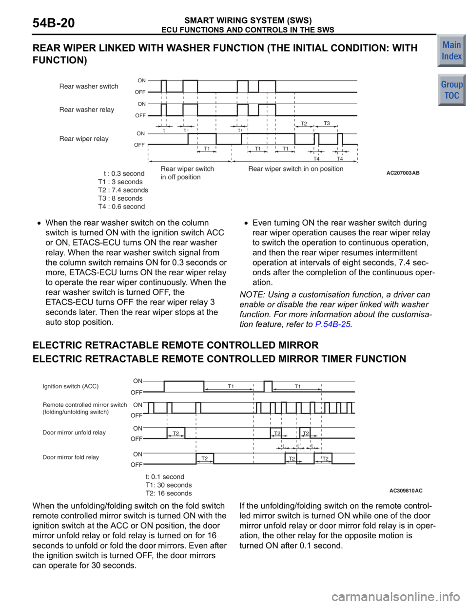
REAR WIPER LINKED WITH WASHER FUNCTION (THE INITIAL CONDITION: WITH
FUNCTION)
AC207003AB
t
tt
ON
OFF
ON
OFF
ON
OFF T1T1 T1T2
T3
T4 T4 t : 0.3 second
T1 : 3 seconds
T2 : 7.4 seconds
T3 : 8 seconds
T4 : 0.6 second Rear wiper switch
in off position
Rear wiper switch in on position
Rear washer switch
Rear washer relay
Rear wiper relay
•Whe
n the re ar wash er swit ch on the column
switch is tu
rned ON with th e ign i tio n switch ACC
or ON, ET
ACS-ECU t u rns ON the rear wash er
relay
. When the re ar washe r switch signa l from
th
e co lu m n swi t c h re ma in s ON f o r 0. 3 se co nd s or
more, ET
ACS-ECU turns ON the r ear wiper relay
to o
perate the rea r wiper continuously . Wh en the
rear
wa sher switch is turned OFF , the
ET
ACS-ECU turns OFF the rea r wiper relay 3
se
cond s later . Th en the rear wip e r sto p s at th e
aut
o sto p positio n.•Even turning ON the rea r wa sher switch during
rear
wiper op eratio n ca uses the r ear wipe r relay
to switch the o
peration to continuou s ope ration ,
and
then t he rear wiper resumes intermittent
ope
ration at interva l s of eig h t se cond s, 7. 4 sec
-
onds af ter t he co mpletion of the con t inuo us op er-
ation.
NOTE: Using a cust omisation fun c tio n , a d r ive r can
enable or disab l e th e rear wip e r linked with washer
funct
i
on. F o r mo re inf o rmation ab out th e customisa
-
tion feature, refer to P.54B-25.
ELECTRIC RETRACT ABLE RE MOTE CONTROLLED MIRROR
ELECTRIC RETRACTABLE REMOTE CONTROLLED MIRROR TIMER FUNCTION
AC309810
Ignition switch (ACC)
AC
t: 0.1 second
T1: 30 seconds
T2: 16 seconds
ON
OFF
T2
T2
T2
T2
T2 T2
t
tt
T1
T1
OFFON
OFF
ON
OFF ON
Door mirror unfold relay
Door mirror fold relay Remote controlled mirror switch
(folding/unfolding switch)
When th
e unfo l din g /folding switch on t he fold switch
remote
controlled mir r or switch is turn ed ON with the
ignition
switch at th e ACC o r ON po sition, th e door
mirro
r unfold relay or fold r e lay is turned on for 16
seconds
t o unfold or fold the d oor mirrors. Even af ter
the ig
nition switch is tu rned OFF , the do or mirrors
can o
perate for 30 seconds.If the un fold ing/f o lding switch o n the remote con t rol-
led mirror switch is turne d ON while on e of th e door
mirro
r unfold relay or door mirror fo ld relay is in op er
-
ation, the o t her relay fo r the o pposite motio n is
turned
ON af ter 0.1 second.
Page 287 of 364
ECU FUNCTIONS AND CONTROLS IN THE SWS
SMART WIRING SYSTEM (SWS)54B-21
NOTE: Whether the door mirrors are at the unfolding
or folding position is determined according to the
memory of the door mirror fold relay operated previ
-
ously. For this reason, if the door mirrors are manu-
ally retracted, they may not move when the
unfolding/folding switch on the fold switch remote
controlled mirror switch is pressed next time.
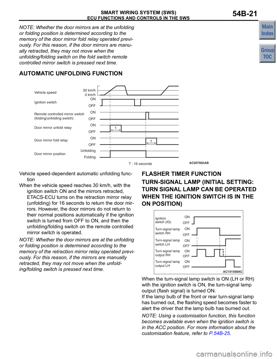
AUTOMATIC UNFOLDING FUNCTION1.
AC207002AB
ON
OFF ON
OFF ON
OFF ON
OFF
T
T
Ignition switch 30 km/h
0 km/h
Unfolding Folding
Vehicle speed
Remote controlled mirror switch
(folding/unfolding switch)
Door mirror position Door mirror unfold relay
Door mirror fold relay
T : 16 seconds
Ve hicle speed-d epend ent au tomat i c u n fold ing func-
tion
When th e ve hicle speed re ache s 30 km/h, with the
ig nition switch ON and the mirrors retracted,
ET ACS-ECU turns on the retraction mirror relay
(unf olding) for 16 se cond s to return th e door mir
-
rors. However, the door mirrors do not return to
the
i r normal p o sitions auto m atically if the ignition
switch is tu
rned fro m OFF to ON, and then th e
unf
olding/folding switch on the remote contro lled
mirror switch
is operate d .
NOTE: Whe t her the door mirrors are at th e unfo l din g
or fold
ing p o sition is d e termined accordin g to th e
memory o f the re traction mirror re lay operat ed previ
-
ously. For th is re ason , if t he mirrors are manually
retract
ed, the y may n o t mo ve when the u n fold
-
ing/folding switch is pre s sed next time.
FLASHER TIMER FUNCTION
TURN-SIGNAL LAMP (I NITIAL SETTING:
TURN SIGNAL LAMP CAN BE OPERA
T ED
W
H EN THE IGNITION SW ITCH IS IN THE
ON POSITION)
AC101508
ON
OFF
ON
OFF
ON
OFF
ON
OFF
ON
OFF
Ignition
switch (IG)
Turn-signal lamp
switch RH
Turn-signal lamp
switch LH
Turn-signal lamp
output RH
Turn-signal lamp
output LH
AC
When th
e turn-sign a l lamp switch is ON (LH o r RH)
with the
ignition switch is ON, t he turn -sig nal lamp
output
(flash signal) is turned ON.
If the lamp bulb of the front o r rear turn -sig nal lamp
has burned out, the flashing speed beco
m es faster to
alert t
he driver th at the lamp bulb has burne d out.
NOTE: Using a cust omisation fun c tio n , this fu nction
beco
m
es ava ilab l e even whe n the ignit i on switch is
in the
ACC po sit i on. F o r mo re info rmation ab out th e
customisation fe ature, re fer to
P.54B-25.
Page 288 of 364
ECU FUNCTIONS AND CONTROLS IN THE SWS
SMART WIRING SYSTEM (SWS)54B-22
HAZARD LAMP
AC101509
ON
OFF
ON
OFF
ON
OFF
Hazard lamp
switch
Turn signal
lamp output
RH
Turn signal
lamp output
LH
AC
When th
e hazard lamp switch inp u t signal turning
from OFF
to ON is dete c te d, the fla s h i ng st a t es tu rns
over b
y the signal (When th e hazard lamp is n o t
blin
kin g , it b lin ks. If it is b linking , it tu rns o f f).
NOTE: .
1.The push -return switch is adop ted for t he hazard
la mp switch .
2. Even if th e lamp bulb has burn ed o u t, the fla s hing
sp eed o f the ha zard lamp is not chang ed.
TURN-SIGNAL LAMP INDICAT O R
The ETACS-ECU sen d s th e turn sign al lamp indica-
tor ON sig nal to the combin ation mete r throu gh CAN
communicat
i on in synchronization with the turn sig
-
nal lamp operat ion. T he co mbination me ter receives
the tran
smitted sig nal a nd turns ON o r OFF the
turn-signal lamp indicator
.
HEADLAMP
HIGH-BEAM INDICA T O R
The ETACS-ECU sends th e high be am in dica tor ON
sig
nal to the comb ination meter th rough CAN co m
-
munication in synchr onizatio n with t he high bea m
headlamp
operation. T he co mbinatio n me ter
receives the
transmit t ed signa l and turns ON o r OF F
the high be
am indicator .
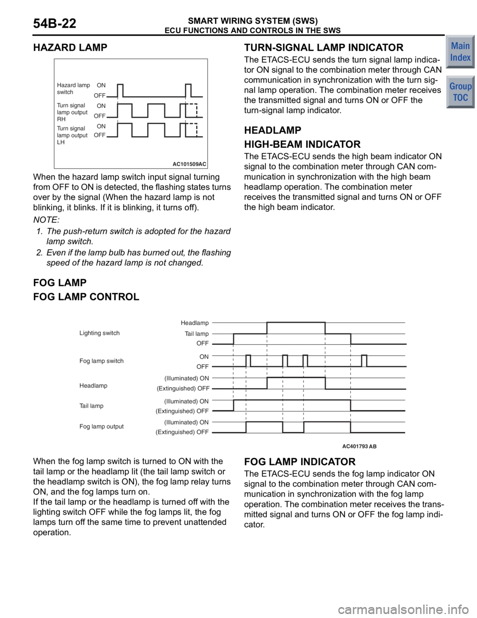
FOG LAMP
FOG LAMP CONTROL
AC401793AB
OFFON
(Extinguished) OFF (Illuminated) ON
(Extinguished) OFF (Illuminated) ON Tail lamp
Headlamp
OFF
Fog lamp switch Lighting switch
Headlamp
Tail lamp
(Extinguished) OFF(Illuminated) ON
Fog lamp output
When th e fog lamp switch is turn ed to ON with th e
t
a il lamp o r the h eadla m p lit (th e t a il lamp switch or
the hea
dlamp switch is ON), the fog lamp relay turns
ON, and
the fo g lamp s turn on.
If the ta il la mp or the he adlamp is turn ed of f with th e
ligh
t ing switch OF F while the fo g lamp s lit, the fog
lamp
s turn o f f the same time to prevent una ttende d
operation.
FOG LAMP INDICAT O R
The ETACS-ECU sen d s th e fog lamp indicat o r ON
sig
nal to the comb ination meter th rough CAN co m
-
munication in synchr onizatio n with t he fog lamp
operation.
The comb ination meter receives the trans
-
mitted signal and t u rns ON or OFF the fog lamp indi-
cator.
Page 289 of 364
ECU FUNCTIONS AND CONTROLS IN THE SWS
SMART WIRING SYSTEM (SWS)54B-23
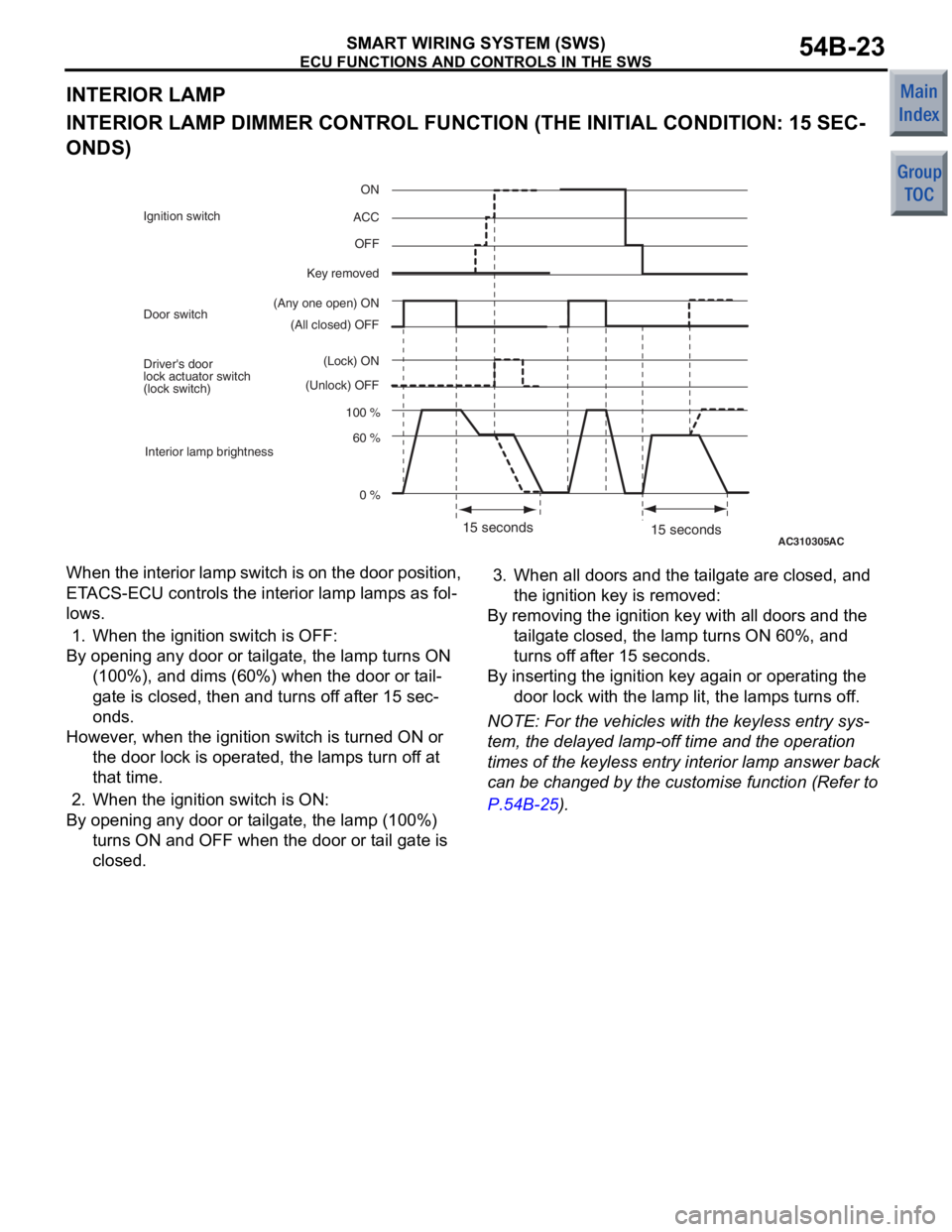
INTERIOR LAMP
INTERIOR LAMP DIMMER CONTROL FUNCTION (THE INITIAL CONDITION: 15 SEC-
ONDS)
AC31030515 seconds
(All closed) OFF
(Any one open) ON ON
OFF
Key removed ACC
100 % 0 %
60 %
Door switch
(Unlock) OFF(Lock) ON
Driver's door
lock actuator switch
(lock switch)
Interior lamp brightness
Ignition switch
15 secondsAC
Wh
en t h e int e r i or lamp switch is o n th e do or p o sitio n ,
ET
ACS-ECU controls the inte rior lamp lamp s as fol
-
lows.
1.Whe n the ignit i on switch is OFF:
By opening a n y d oor or t a ilgate , the lamp turns ON
(100 %), and dims (60 % ) when t he doo r or t a il
-
gate is clo s ed, then a nd turn s of f af ter 15 sec-
onds.
However , whe n the ignit i on switch is turned ON or
the door lock is operat ed, the lamp s turn of f a t
tha t time.
2.Whe n the ignit i on switch is ON:
By opening a n y d oor or t a ilgate , the lamp (100%)
turn s ON a nd OFF when t he doo r or t a il gate is
cl ose d .
3.Whe n all doors and the t a ilgate are close d , and
the ignition key is remo ved:
By removing the ignition key with a ll d oors a nd the
t a ilgate closed, th e lamp tu rns ON 60%, a nd
turn s of f af ter 15 seconds.
By inserting the ignition key again or op erating the
doo r lock wit h the lamp lit, the lamp s turns of f.
NOTE: For t he ve hicles with th e keyless e n try sys-
tem, the delaye d lamp-off time and t he ope ration
time
s of the keyless entry inte rior lamp answer b a ck
can b
e ch anged by th e cu stomise function (Re f er to
P.54B-25).
Page 290 of 364
ECU FUNCTIONS AND CONTROLS IN THE SWS
SMART WIRING SYSTEM (SWS)54B-24
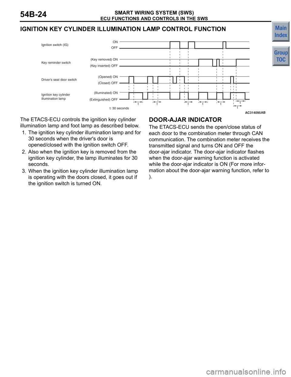
IGNITION KEY CYLINDER ILLUMINATION LAMP CONTROL FUNCTION
AC314095
t: 30 seconds
(Closed) OFF
(Opened) ON ON
OFF
(Key removed) ON
(Key inserted) OFF
(Illuminated) ON
(Extinguished) OFF
Driver's seat door switch Key reminder switch
Ignition key cylinder
illumination lamp Ignition switch (IG)
tt ttt tt
AB
The ETACS-ECU con t rols the ignition key cylinde r
illuminatio
n lamp an d foot lamp as d e scribe d below .
1. T he ig nit i o n key cy lin de r ill umi n a t io n la mp an d fo r
30 seconds wh en the driver's d oor is
ope ned/closed with the ignition switch OFF .
2.Also when t he ig nition ke y is remove d from the
ig nition ke y cylinder , the lamp illuminates for 30
se cond s.
3.Whe n the ignit i on key cylind e r illumination lamp
is oper ating with the doors closed , it g oes o u t if
the ignition switch is turne d ON.
DOOR-AJAR INDICAT O R
The ETACS-ECU sen d s th e open /close st atus of
each
door to the comb ination meter th rough CAN
communicat
i on. The comb ination meter receives the
transmitte
d signal and t u rns ON and OFF t he
door-ajar in
dicator . Th e door-a jar indicator f l ashes
wh
en the door-ajar warning fun c tio n is activat ed
wh
ile the doo r-ajar indicato r is ON (For more infor
-
mation about the door-ajar warning fun c tio n , refe r to
).