MITSUBISHI DIAMANTE 1900 User Guide
Manufacturer: MITSUBISHI, Model Year: 1900, Model line: DIAMANTE, Model: MITSUBISHI DIAMANTE 1900Pages: 408, PDF Size: 71.03 MB
Page 11 of 408
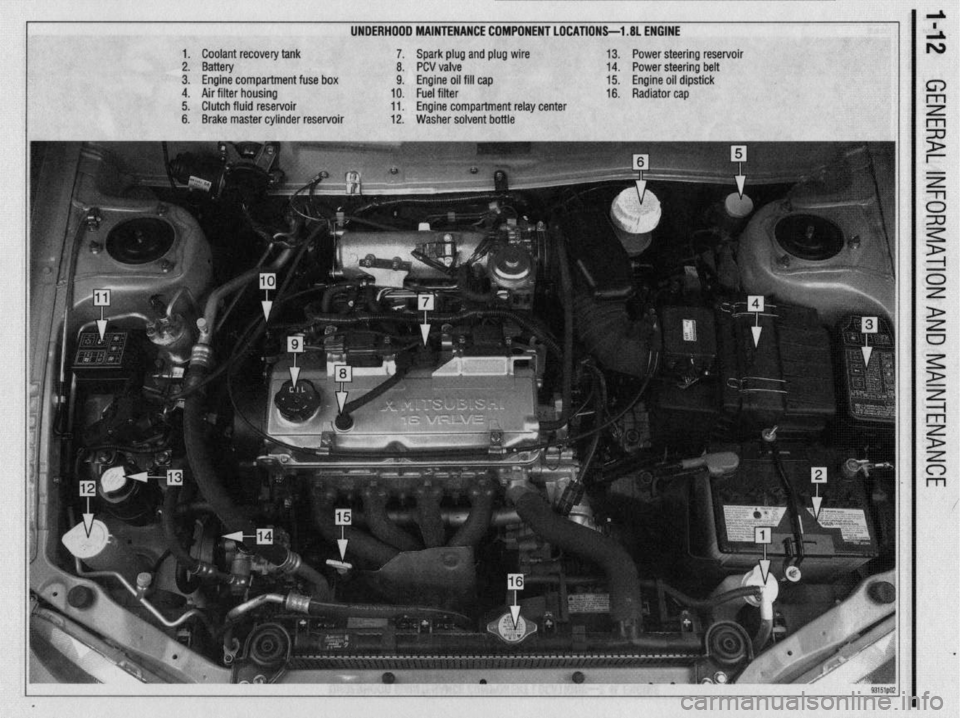
UNDERHOOD MAINTENANCE COMPONENT LOCATIONS-l .8L ENGINE
1. Coolant recovery tank
2. Battery
3. Engine compartment fuse box
4. Air filter housing
5. Clutch fluid reservoir
6. Brake master cylinder reservoir 7. Spark plug and plug wire
8. PCV valve
9. Engine oil fill cap
10. Fuel filter
11. Engine compartment relay center
12. Washer solvent bottle 13. Power steering reservoir
14. Power steering belt
15. Engine oil dipstick
16. Radiator cap
Page 12 of 408
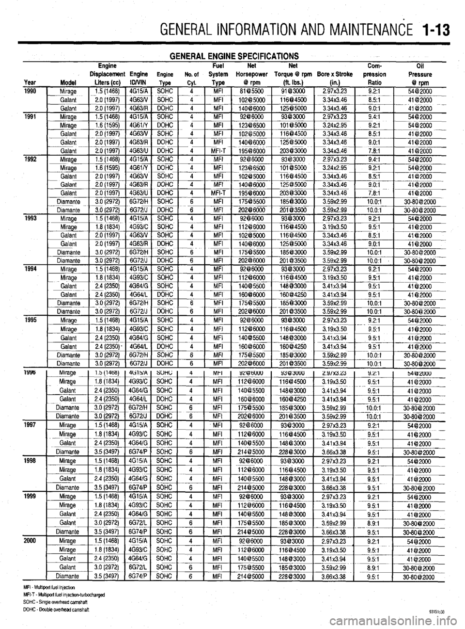
GENERALINFORMATIONAND MAlNTENANdE 1-13
Engine GENERAL ENGINE SPECIFICATIONS Fuel Net Net
Com-
Oil
Displacement Engine Engine No. of System Horsepower Torque @ rpm Bore x Stroke pression
Pressure
MFI Mult+wt fuel mfectw,
MFI-T - Multlporl fuel mfectlon-turbocharged
SOHC - Smgle overhead camshaft
DOHC - Double OvedEad camshaft
Page 13 of 408
l
l-14 GENERALINFORMATIONAND MAINTENANCE
Proper maintenance and tune-up is the key to long
and trouble-free vehicle life, and the work can yield
its own rewards. Studies have shown that a properly
tuned and maintained vehicle can achieve better gas
mileage than an out-of-tune vehicle. As a conscien-
tious owner and driver, set aside a Saturday morning,
say once a month, to check or replace items which
could cause major problems later. Keep your own
personal log to jot down which services you per-
formed, how much the parts cost you, the date, and
the exact odometer reading at the time. Keep all re-
selfer, these receipts are the only proof you have that ceipts for such items as engine oil and filters, so that
they may be referred tp in case of related problems or
to determine operating expenses. As a do-it-your- the required maintenance was performed. In the event
of a warranty problem, these receipts will be invalu-
able.
The literature provided with your vehicle when it
was originally delivered includes the factory recom-
mended maintenance schedule. If you no longer have
this literature, replacement copies are usually avail-
able from the dealer. A maintenance schedule is pro-
vided later in this section, in case you do not have
the factory literature. *
REMOVAL &INSTALLATION
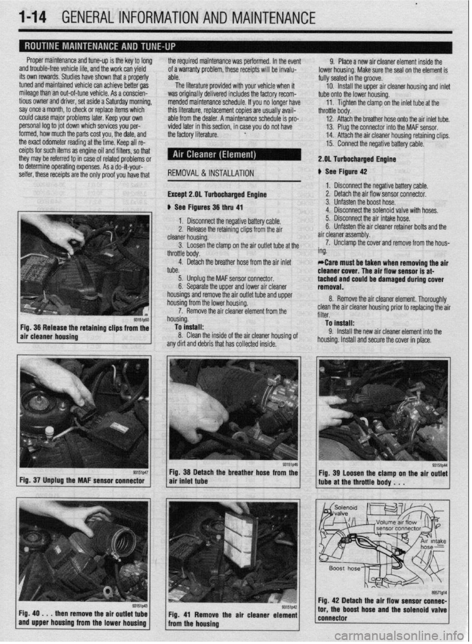
Except 2.gL Turbocharged Engine
b See Figures 36 thru 41 9. Place a new air cleaner element inside the
lower housing. Make sure the seal on the element is
fully seated in the groove.
10. Install the upper air cleaner housing and inlet
tube onto the lower housing.
11. Tighten the clamp on the inlet tube at the
throttle body.
12. Attach the breather hose onto the air inlet tube.
13. Plug the connector into the MAF sensor.
14. Attach the air cleaner housing retaining clips.
15. Connect the negative battery cable.
2.DL Turbocharged Engine
b See Figure 42
1. Disconnect the negative battery cable.
2. Detach the air flow sensor connector.
3. Unfasten the boost hose.
4. Disconnect the solenoid valve with hoses.
93151p50 Fig. 36 Release the retaining clips from the
air cleaner housing
r3151p47 Fig. 37 Unplug the MAF sensor connector
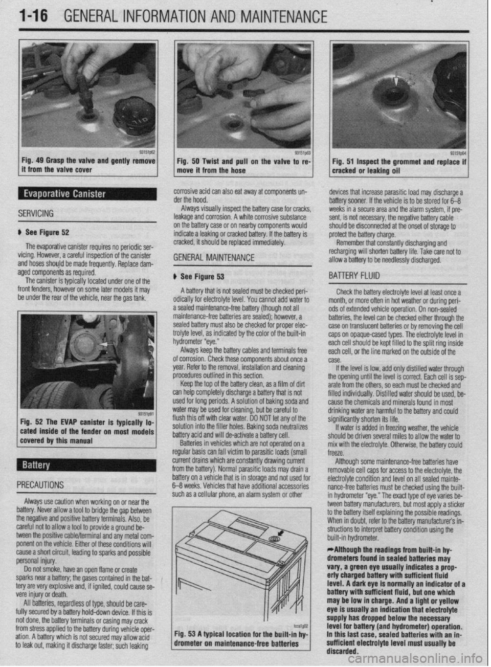
Fig. 49
. . . then remove the air outlet tube
and upper housing from the lower housing 1. Disconnect the negative battery cable. 5. Disconnect the air intake hose.
2. Release the retaining clips from the air 6. Unfasten tie air cleaner retainer bolts and the
cleaner housing. air cleaner assembly.
3. Loosen the clamp on the air outlet tube at the 7. Unclamp the cover and remove from the hous-
throttle body. ing.
4. Detach the breather hose from the air inlet
tube. *Care must be taken when removing the air
cleaner cover. The air flow sensor is at-
5. Unplug the MAF sensor connector.
6. Separate the upper and lower air cleaner tached and could be damaged during cover
removal.
housings and remove the air outlet tube and upper
housing from the lower housing.
7. Remove the air cleaner element from the
housing.
To install:
8. Clean the inside of the air cleaner housing of
any dirt and debris that has collected inside. 8. Remove the air cleaner element. Thoroughly
clean the air cleaner housing prior to replacing the air
filter.
To install:
9. Install the new air cleaner element into the
housing. Install and secure the cover in place.
Fig. 38 Detach the breather hose from the
air tniet tube
Fig. 41 Remove the air cleaner element
from the housing Fig. 39 Loosen the clamp on the air outlet
tube at the throttle body . . .
Fig. 42 Detach the air flow sensor connec-
tor, the boost hose and the solenoid valve
connector
Page 14 of 408
GENERALINFORMATIONAND MAINTENANCE l-15
10. install the air cleaner assembly and the re- *Wrap shop towels around the fitting that is
tainer bolts. being dtsconnected to absorb residual fuel in
11. Connect the air intake hose. the lines. 9. While holding the fuel filter nut with aback-
up wrench, tighten the banjo bolt to 22 ft. Ibs. (30
Nm). Tighten the flare nut to 25 ft. Ibs. (35 Nm), with
12. Attach the solenoid valve.
4. Cover the hose connection with shop towels to a back-up wrench on the nut.
13. Connect the boost hose.
14. Attach the air flow sensor connector. prevent any splash of fuel that could be caused by 10. Tighten the filter mounting bolts to 10 ft. Ibs.
residual pressure in the fuel pipe line. Hold the fuel (14 Nm).
15. Connect the negative battery cable. 11.
filter nut securely with a backup wrench, then remove Connect the negative battery cable. Turn the
REMOVAL &INSTALLATION the banjo bolt on the engine feed line. Disconnect the
high-pressure fuel line from the filter. Remove and
discard the gaskets.
5. While holding the fuel filter nut securely with a
back-up wrench, loosen the filter feed pipe flare nut key to the ON position to pressurize the fuel system
and check for leaks.
12. If repairs of a leak are required, remember to
release the fuel pressure before opening the fuel sys-
tern.
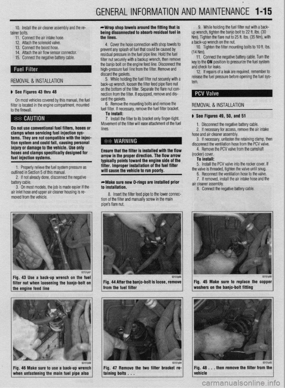
u See Figures 43 thru 48
On most vehicles covered by this manual, the fuel
filter is located in the engine compartment, mounted
to the firewall.
Do not use conventional fuel filters, hoses or
clamps when servicing fuel injection sys
terns. They are not compatible with the injec-
tion
system and could fail, causing personal
injury or damage to the vehicle. Use only
hoses and clamps specifically designed for
fuel injection systems.
1. Properly relieve the fuel system pressure as
outlined in Section 5 of this manual. on the bottom of the filter. Separate the flare nut con-
nection from the filter. If equipped, remove and dis-
card the gaskets.
6. Remove the mounting bolts and remove
. ,,,. ,.
.a r I,.,< I the
ruer rrrter. II necessary, remove me ruer rrrrer oracket.
To install:
7. Install the filter to its bracket only finger-tight.
Movement of the filter will ease attachment of the fuel
lines.
Ensure that the filter is installed with the flow
arrow in the proper direction. The flow arrow
typically points toward the engine side of the
filter. improper installation of the fuel filter
will cause the vehicle to run poorly.
2. If not already done, disconnect the negative REMOVAL&INSTALLATION
u See Figures 49, 50, and 51
1, Disconnect the negative battery cable.
2. If necessary for access, remove the air intake
hose and air cleaner assembly.
3. If necessary, unfasten the retaining clamp, then
disconnect the ventilation hose from the PCV valve.
4. Remove the PCV valve from the camshaft
(rocker) cover.
To install:
5. Install the PCV valve into the rocker cover. If
the valve is threaded, tighten the valve until snug.
battery cable.
3. On most models. the iob is made easier if the
air inlet hose and upper air cleaner housing is re-
moved from the vehicle. *Make sure new O-rings are installed prior
to installation.
8. Insert the filter feed pipe to the lower connec-
tion of the filter and manually screw in the main
pipe’s flare nut. 6. Reconnect the ventilation hose to the valve.
7. If removed, install the air intake hose and the
a .ir cleaner assembly.
8. Connect the negative battery cable.
Fig. 43 Use a back-up wrench on the fuel
I I
93151@3
filter nut when loosening the banjo-bolt on Fig. 44 After the banjo-bolt is loose, remove
I
1 the engine feed line - from the fuel filter
93151p93 Fig. 48 Make sure to use a back-up wrench
1 when unfastening the main fuel pipe also 1 Fig. 47 Remove the two filter bracket re-
taining bolts . . . Fig. 45 Make sure to replace the copper
washers on the banjo-bolt fitting
Fig. 48 . . . then remove the filter from the
vehicle
Page 15 of 408
*
l-16 GENERALINFORMATIONAND MAINTENANCE
Fig. 49 Grasp the valve and gently remove
Fig. 50 Twist and pull on the valve to re-
it from the valve cover
move it from the hose Fig. 51 Inspect the grommet and replace if
cracked or leaking oil
SERVICING
corrosive acid can also eat away at components un-
der the hood.
Always visually inspect the battery case for cracks,
leakage and corrosion. A white corrosive substance
u See Figure 52
The evaporative canister requires no periodic ser-
vicing. However, a careful inspection of the canister
and hoses should be made frequently, Replace dam- on the battery case or on nearby components would
indicate a leaking or cracked battery. If the battery is
cracked, it should be replaced immediately. GENERALMAINTENANCE '_
devices that increase parasitic load may discharge a
battery sooner. If the vehicle is to be stored for 6-B
weeks in a secure area and the alarm system, if pre-
sent, is not necessary, the negative battery cable
should be disconnected at the onset of storage to
protect the battery charge.
Remember that constantly discharging and
recharging will shorten battery life. Take rare not to
allow a battery to be needlessly discharged.
aged components as required.
The canister is typically located under one of the
front fenders, however on some later models it may
be under the rear of the vehicle, near the gas tank,
r on most models # See Figure 53
A battery that is not sealed must be checked peri-
odically for electrolyte level. You cannot add water to
a sealed maintenance-free battery (though not all
maintenance-free batteries are sealed); however, a
sealed battery must also be checked for proper elec-
trolyte level, as indicated by the color of the built-in
hydrometer “eye.”
Always keep the battery cables and terminals free
of corrosion. Check these components about once a
year. Refer to the removal, installation and cleaning
procedures outlined in this section,
Keep the top of the battery clean, as a film of dirt
can help completely discharge a battery that is not
used for long periods. A solution of baking soda and
water may be used for cleaning, but be careful to
flush this off with clear water. DO NOT let any of the
solution into the filler holes. Baking soda neutralizes
battery acid and will de-activate a battery cell.
Batteries in vehicles which are not operated on a
regular basis can fall victim to parasitic loads (small
BA-ITERY FLUID
Check the battery electrolyte level at least once a
month. or more often in hot weather or during peri-
ods of extended vehicle operation. On non-sealed
batteries, the level can be checked either through the
case on translucent batteries or by removing the cell
caps on opaque-cased types. The electrolyte level in
each cell should be kept filled to the split ring inside
each ceil, or the line marked on the outside of the
case.
If the level is low, add only distilled water through
the opening until the level is correct. Each cell is sep-
arate from the others, so each must be checked and
filled individuallv. Distilled water should be used, be-
cause the chemicals and minerals found in most
drinking water are harmful to the battery and could
significantly shorten its life.
If water is added in freezing weather, the vehicle
should be driven several miles to allow the water to
mix with the electrolyte. Otherwise, the battery could
freeze.
current drains which are constantly drawing current
from the battery). Normal parasitic loads may drain a Although some maintenance-free batteries have
removable cell caos for access to the electrolyte, the
cause a short circuit, leading to sparks and possible
personal injury.
Do not smoke, have an open flame or create
sparks near a battery; the gases contained in the bat-
tery are very explosive and, if ignited, could cause se-
vere injury or death.
All batteries, regardless of type, should be care-
fully secured by a battery hold-down device. If this is
not done, the battery terminals or casing may crack
from stress applied to the battery during vehicle oper-
ation. A battery which is not secured may allow acid
to leak out, making it discharge faster; such leaking m / built-in hydrometer. .
*Although the readings from built-in hy-
drometers found in sealed batteries may
vary, a green eye usually indicates a prop
erly charged battery with sufficient fluid
level. A dark eye is normally an indicator of a
battery wlth sufficient fluid, but one which
may be low in charge. And a light or yellow
eye is usually an indication that electrolyte
supply has dropped below the necessary
tcu1@32 Fig. 53 A typical location for the built-in hv- level for battery (and hydrometer) operation.
drometer on maintenan
ce-free batteries ’ I In this last case. sealed batteries with an in-
sufficient electrolyte level must usually be
’ discarded.
Page 16 of 408
G,ENERALlNFORMATlONAND MAINTENANCE l-17
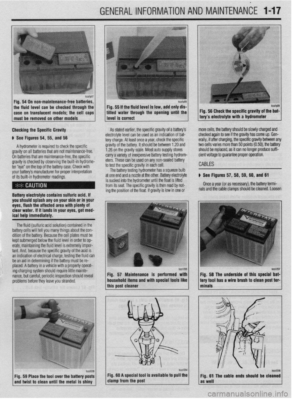
Fig. 54 On
non-maintenance-free
batteries,
the fluid level can be checked through the Fig. 55 If the fluid
level
is low, add only dis-
1 case on translucent models; the cell caps 1
must be removed on other models
1 1 tilled water through the opening until the
1 level is correct
Checking the Specific Gravity
A hydrometer is required to check the specific
# See Figures 54, 55, and 56
gravity on all batteries that are not maintenance-free.
On batteries that are maintenance-free, the soecific
gravity is checked by observing the built-in hydrome-
ter “eye” on the top of the battery case. Check with
your battery’s manufacturer for proper interpretation
of its built-in hvdrometer readinas. gravity of the battery. It should be between 1.20 and As stated earlier, the specific gravity of a battery’s
electrolyte level can be u
1.26 on the gravity scale. Most auto supply stores sed as an indication of bat-
tery charge. At least once
carry a variety of inexpensive battery testing hydrom- ? a year, check the specific
eters. These can be used on any non-sealed battery
, , , ,,
.,, . .
IO rest me specmc gravny in each cell.
The battery testing hydrometer has a squeeze bulb
at one end and a nozzle at the other. Battery electrolyte
the hydrometer until the float is lifted
-he specific gravity is then read by not-
n of the float. If gravity is low in one or mg tne posrtro
Battery electrolyte contains sulfuric acid. If
you should splash any on your skin or in your
eyes, flush the affected area with plenty of
clear water. If it lands in your eyes, get med-
ical help immediately.
The fluid (sulfuric acid solution) contained in the
battery cells will tell you many things about the con-
dition of the battery. Because the cell plates must be
kept submerged below the fluid level in order to op-
erate, maintaining the fluid level is extremely impor-
tant. And. because the soecific aravitv of the acid is
an indication of electrical charge, testing the fluid can
be an aid in determining if the battery must be re-
placed. A battery in a vehicle with a properly operat-
ing charging system should require little mainte-
nance, but careful, periodic inspection should reveal
problems before they leave you stranded. Fig. 57 Maintenance is performed with
Fig. 58 The underside of this special bat-
household items and with special tools like
tery tool has a wire brush to clean post ter-
I this post cleaner
I 1 minals Fig. 56 Check the specific gravity of the bat-
tery’s electrolyte with a hydrometer
more cells, the battery should be slowly charged and
Lhecked aqain to see if the aravitv has come
UP. Gen-
erally, if affer charging, the specific gravity between any
two cells varies more than 50 points (0.50) the battery
should be replaced, as it can no longer produce suffi-
cient voltage to guarantee proper operation.
CABLES
) See Figures 57, 56, 69, 60, and 61
Once a year (or as necessary), the battery termi-
nals and the cable clamps should be cleaned. Loosen
Page 17 of 408
l
1-18 GENERALINFORMATIONAND MAINTENANCE
the clamps and remove the cables, negative cable
first. On batteries with posts on top, the use of a
puller specially made for this purpose is recom-
mended. These are inexoensive and available in most alternator or turn the adjusting bolt to adjust belt ten-
sion. Once the desired value is reached, secure the
bolt or locknut and recheck tension.
d”t” lJdlL> X”lt;>. 31°C LtXlllllldl lJdllt2)’ MLJIC, dlt’ X- cured with a small bolt. ST& I REMOVAL &INSTALLATION
Clean the cable clamps and the battery terminal I
with a wire brush, until all corrosion, grease, etc., is
removed and the metal is shinv. It is esneciallv imnnr-
tant to c
knife is useful nere), since a smart
material or oxidation there will pre Clean the cable clamps and the battery terminal
with a wire brush, until all corrosion, grease, etc., is
removed and the metal is shiny. It is especially impor-
tant to clean the inside of the clamp thoroughly (an old
knife is useful here), since a small deposit of foreign
material or oxidation there will prevent a sound electri-
cal connection and inhibit either starting or charging.
Special tools are available for cleaning these parts,
one type for conventional top post batteries and an-
other type for side terminal batteries. It is also a good
idea to apply some dielectric grease to the terminal, as
this will aid in the prevention of corrosion,
After the clamps and terminals are clean, reinstall
the cables, negative cable last; DO NOT hammer the
clamps onto battery posts. Tighten the clamps se-
curely, but do not distort them. Give the clamps and
terminals a thin external coating of grease after in-
stallation, to retard corrosion.
Check the cables at the same time that the terminals
are cleaned. If the cable insulation is cracked or bro-
ken, or if the ends are frayed, the cable should be re-
placed with a new cable of the same length and gauge.
CHARGING
the cables, negative cable last; DO NOT hammer the
curely, but do not distort them. Give the clamps and
terminals a thin external coating of grease after in-
stallation, to retard corrosion.
Check the cables at the same time that the terminals
are cleaned. If the cable insulation is cracked or bro-
ken, or if the ends are frayed, the cable should be re-
placed with a new cable of the same length and aauae.
CHARGING
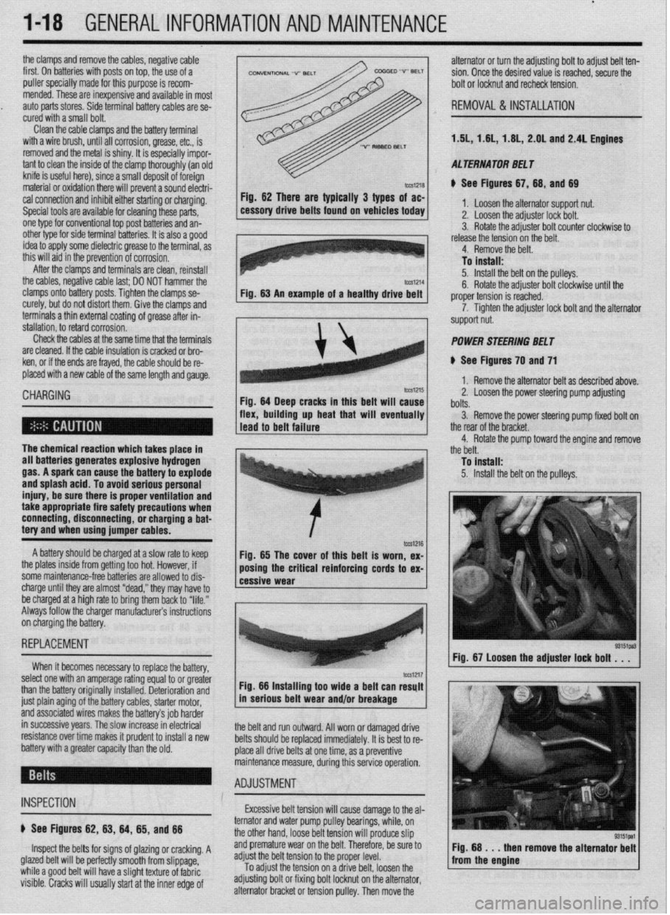
Fig. 62 mere are typically 3 types of ac-
cessory drive belts found on vehicles today 1. Loosen the alternator support nut.
2. Loosen the adjuster lock bolt.
3. Rotate the adjuster bolt counter clockwise to
I .I , . . . * . .
I Tn i”et*ll* Fig. 62 There are typically 3 types of ac-
Fig. 64 Deep cracks in this belt will cause
flex, building up heat that will eventually 11, 1.8L, 2.OL and 2.4L Engines
cal connection and inhibit either starting or charging.
Special tools are available for cleaning these parts,
one type for conventional top post batteries and an-
other type for side terminal batterin, I+ if QI@* 3 nnnd
idea to apply some dielectric grr
this will aid in the prevention of ,,vIIuaIUII.
After the clamps and terminals are clean, reinstall 1.5L, 1.6
AL TERNA TOR BE1 T
e See Figures 67,68, and 69
1. Loosen the alternator support nut.
2. Loosen the adjuster lock bolt.
3. Rotate the adjuster bolt counter clockwise to
release the tension on the belt.
4. Remove the belt.
To install:
5. Install the belt on the pulleys.
6. Rotate the adjuster bolt clockwise until the
proper tension is reached.
7. Tighten the adjuster lock bolt and the alternator
support nut.
POWER STEERING BELT
8 See Figures 70 and 71
1. Remove the alternator belt as described above.
2. Loosen the power steering pump adjusting
bolts.
3. Remove the power steering oumo fixed bolt on
R Rntatn the cxiillrtm hnit A&+,& until the r -r- .- .- ._.. ._ .______
7. Tighten the adjuster lock bolt and the alternator
support nut.
POWER STEERING BELT
1 ..“‘.I ““..Y...Y up II”“. ..IU. ..m.*
1 lead to belt failure V.
I
I
The chemical reaction which takes place in - 1 the rear of the bracket.
4. Rotate the pump toward the engine and remove
the belt.
all batteries generates explosive hydrogen
gas. A spark can cause the battery to explode
and splash acid. To avoid serious personal
injury, be sure there is proper ventilation and
take appropriate fire safety precautions when
connecting, disconnecting, or charging a bat-
tery and when using jumper cables. To fnstall:
5. Install the belt on the pulleys.
A battery should be charged at a slow rate to keep
the plates inside from getting too hot. However, if
some maintenance-free batteries are allowed to dis-
charge until they are almost “dead,” they may have to
be charged at a high rate to bring them back to “life.”
Always follow the charger manufacturers instructions
on charging the battery. 85 The cover of this belt ex-
Fig. is worn,
REPLACEMENT
When it becomes necessary to reolace thn haeoN
‘” yyL’“‘J’ I or oreMer
select one with an amperage rating equal tc .
a ----
than the battery originally installed. Deterioration and
just plain aging of the battery cables, starter motor,
and associated wires makes the battery’s job harder
in successive years. The slow increase in electrical
resistance over time makes it prudent to install a new
battery with a greater capacity than the old. 1 Fig. 67 Loosen the adjuster lock bolt . . .
I ‘-
I -. -_ tm1217 Fig. 66 Installing too wide a belt can resylt
in serious belt wear and/or breakage
the belt and run outward. All worn or damaged drive
belts should be replaced immediately. It is best to re-
place all drive belts at one time, as a preventive
uring this service operation. maintenance measure, d
- ADJUSTMENT : *
INSPECTION Excessive belt tension will cause damage to the al-
e See Figures 62, 83, 64, 65, and 88
Inspect the belts for signs of glazing or cracking. A
glazed belt will be perfectly smooth from slippage,
while a good belt will have a slight texture of fabric
visible. Cracks will usually start at the inner edge of pulley bearings, while, on
It tension will
Droduce slin ternator and water pump
the other hand, loose be
r ------ r
and premature wear on the belt. Therefore, be sure to
adjust the belt tension to the proper level.
To
adjust the tension ’ ’ ’ ” ’ ‘* adjusting bolt or fixing b
alternator bracket or tens on a onve Den. loosen me I Fig. 68 . . . then
from the engine remove the alternator
bolt locknut on the alternator,
iion pulley. Then move the
Page 18 of 408
GENERAL INFORMATION AND MAlNTENANdE l-19
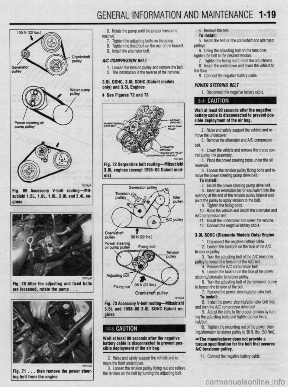
792UQ4 Fig. 69 Accessory V-belt routing-Mii
subishf 1.6L, 1.6L,-1.6L, 2.OL and 2.4L en
gines
33151PM Fig. 70 After the adjusting and fixed bolt!
are loosened, rotate the pump . . .
/ F$71t immtl$mm&a the power ::: 6. Rotate the pump until the proper tension is
reached.
7. Tighten the adjusting bolts on the pump.
8. Tighten the fixed bolt on the rear of the bracket.
9. Install the alternator belt.
A/r: COMPRESSOIl BEL f
1. Loosen the tension oullev and remove the belt.
2. The installation is the reverse of the removal.
.3.gL DGHC, 3.OL SOHC (Gaiant models
only) and 3.5L Engines 4. Remove the belt.
To install:
5. Install the belt on the crankshaft and alternator
pulleys.
6. Using the adjusting bolt on the tensioner,
tighten the belt to the desired tension.
7. Tighten the fixing nut to hold the adjustment.
8. Install the undercover and lower the vehicle to
_,
the tloor.
9. Connect the negative battery cable.
POWER SliEERlNG BEL f
6 See Figures 72 and 73 1. Disconnect the neaative batteN cah+P
-I
Wait at least 60 seconds after the negative
battery cable is disconnected to prevent poS-
sibie deployment of the air bag.
2. Raise and safely support the vehicle and re-
mob re the undercover.
3. Remove the alternator and NC compressor
belt.
4. Lower the vehicle and remove the cruise con-
trol oumn link iW%mblV. 79244Q.37
-- I-- r ---- - _I
Fig. 72 Serpentine belt routing-Mitsubishi 5. Place the power steering hose under the oil
reservoir.
3.OL engines (except 1696-00 Galant mod-
6.
Loosen the tension pulley fixing bolts and re-
els)
Generator pulP
1 move the power steering pump drive belt.
To install:
1 7. install the Dower steerina oumu r+r+v~ hp++
8. Insert an extension bar &eoufvaik;;t”f;;id‘he
opening at the end of the tension pulley bracket and
pivot the pulley to apply tension to the belt.
9. Tighten the fixing bolts.
10. Raise the vehicle and install the alternator and
compressor belt.
Il. Install the undercover and lower +hfi vph+r+p
.I,., .VII.“.Y.
12. Connect the negative battery cable.
I 3.OL SGHC (Diamante Models Onivl Enotne
I ,r ” 1. Disconnect the negative battery cable.
2.’ Loosen the lockbolt on the face nf the A/C _ __.- tensioner pulley.
3
Turn the adiustina bolt of the A/C +fincrnner
pulley to loosen the tension of the A/C belt.
4. Remove the A/C compressor belt.
5.
Loosen the locknut on the face of the power
to loosen the tc
7. Remov
Fig. 73 Accessory V-belt routing-Mitsubishi
3.5L and 1996-00 3.OL SOHC Galant en-
gines steering/alternator tensloner pulley.
6. Turn the adjusting bolt of the tensioner pulley
msion of the belt.
‘e the power steering/alternator belt.
To install:
8. Install the power steering/alternator belt first
.* .* . ,^
ssor drive belt. ana tnen tne A/ti compre:
9. Adjust the belts t+
ing the adjusting bolts anu
II~IIWII pueey tlxmg I the proper tension by turn-
A.:-L I-..-.. I,^, .’
nut/bolt.
10. Tighten the mounting nut of the power steer-
ing/alternator tensioner pulley to 36 ft. Ibs. (50 Nm).
Wait at least 60 seconds after the negative
battery cable is disconnected to prevent pos-
sible deployment of the air bag. -The manufacturer does not provide a
torque specification for the bolt that secures
A/C tensioner pulley.
2. Raise and safely support the vehicle and re- 11. Connect the negative battery cable.
move the front undercover.
3. Loosen the tension pulley fixing nut and relieve
the tension on the belt by turning the adjusting bolt.
Page 19 of 408
.
l-20 GENERALINFORMATIONAND MAINTENANCE
INSPECTION
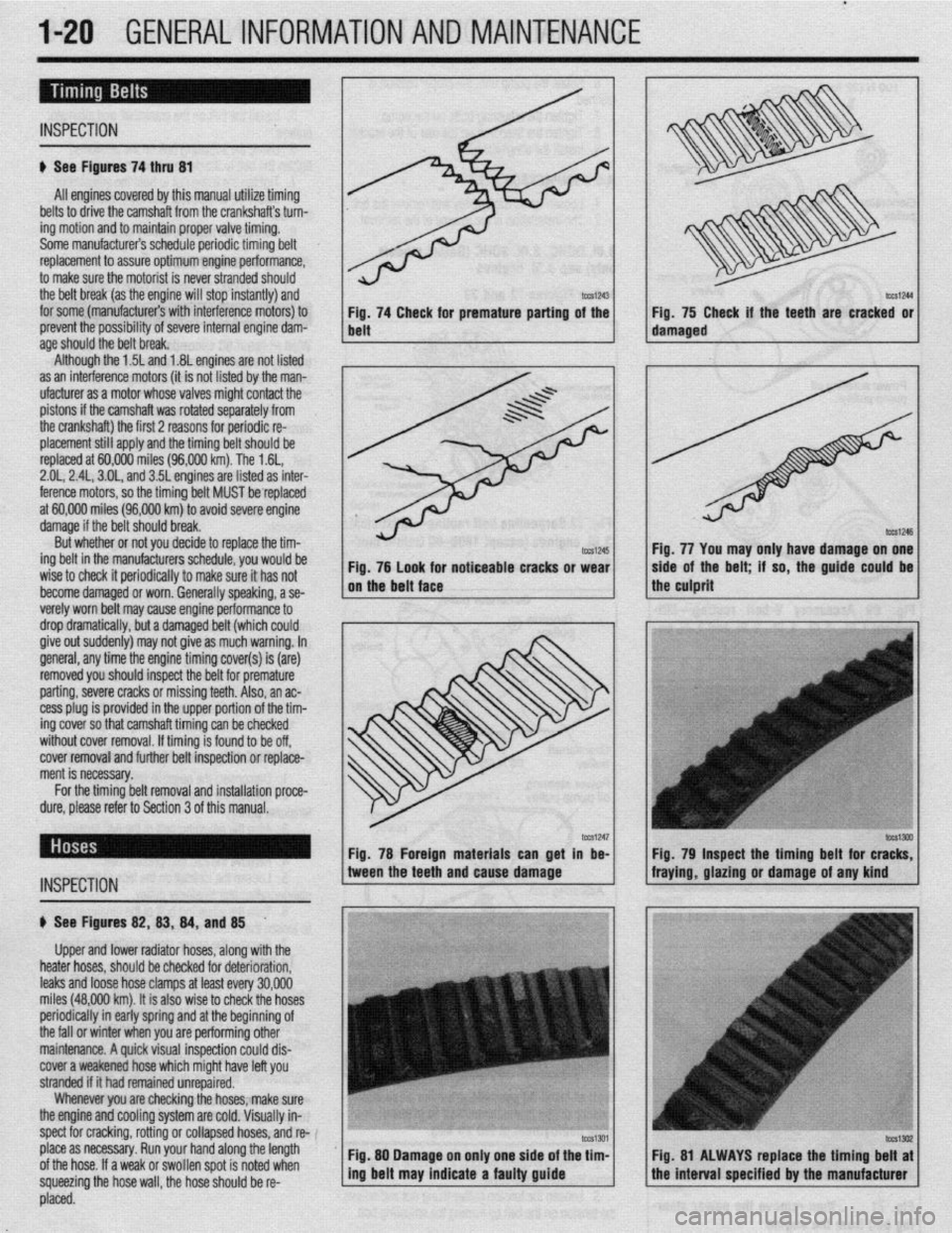
# See Figures 74 thru 81
All engines covered by this manual utilize timing
belts to drive the camshaft from the crankshafts turn-
ing motion and to maintain proper valve timing.
Some manufacturers schedule periodic timing belt
replacement to assure optimum engine performance,
to make sure the motorist is never stranded should
the belt break (as the engine will stop instantly) and
for some (manufacturers with interference motors) to
prevent the possibility of severe internal engine dam-
age
St10Ula the Delt break. Although the 1.5L and 1.8L engines are not listed
as an interference motors (it is not listed by the man-
ufacturer as a motor whose valves might contact the
pistons if the camshaft was rotated separately from
the crankshaft) the first 2 reasons for periodic re-
placement still apply and the timing belt should be
replaced at 60,000 miles (96,000 km). The 1.6L,
2.01,2.4L, 3.OL, and 35L engines are listed as inter-
ference motors, so the timing belt MUST be replaced
at 60,000 miles (96,000 km) to avoid severe engine
damage if the belt should break.
But whether or not you decide to replace the tim-
ing belt in the manufacturers schedule, you would be
wise to check it periodically to make sure it has not
become damaged or worn. Generally speaking, a se-
verelv worn belt mav cause enaine oerformance to
drop~dramatically, but a damaged belt (which could
give out suddenly) may not give as much warning. In
general, any time the engine timing cover(s) is (are)
removed you should inspect the belt for premature
parting, severe cracks or missing teeth. Also, an ac-
cess plug is provided in the upper portion of the tim-
ing cover so that camshaft timing can be checked
without cover removal. If timing is found to be off,
cover removal and further belt inspection or replace-
ment is necessary.
tml245 Fig. 76 look for noticeable cracks or wear
on the belt face
_
For the timing belt removal and installation proce-
dure, please refer to Section 3 of this manual. Fig. 74 Check for premature parting of the
belt
INSPECTION
. 75 Check if the teeth are cracked or
fig. 77 You may only have damage on one
side of the belt; if so, the guide could be
the culprit
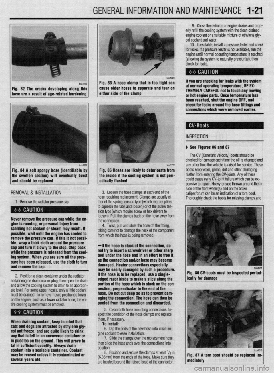
b See Figures 82,8S, 84, and 85 .
Upper and lower radiator hoses, along with the
heater hoses, should be checked for deterioration,
leaks and loose hose clamps at least every 30,000
miles (48,000 km). It is also wise to check the hoses
periodically in early spring and at the beginning of
the fall or winter when you are performing other
maintenance. A quick visual inspection could dis-
cover a weakened hose which might have left you
stranded if it had remained unrepaired.
Whenever you are checking the hoses, make sure
the engine and cooling system are cold. Visually in-
spect for cracking, rotting or collapsed hoses, and w-
place as necessary. Run your hand along the length
of the hose. If a weak or swollen spot is noted when
squeezing the hose wall, the hose should be re- Fig. 78 Foreign materials can get in be- Fig. 79 Inspect the timing belt for c
tween the teeth and cause damage fraying, glazing or damage of any kind
Fig. 80 Damage on only one side of the tim-
I I Fig. 81 ALWAYS replace the timing belt at
ing belt may indicate a faulty guide
the interval specified by the manufacturer
, L placed.
Page 20 of 408
GENERALINFORMATIONAND MAINTENANCE l-21
IWSIZXJ FM. 83 A hose clamn that is taa tiaht can
Fig. 82 The cracks developing along this
hose are a result of age-related hardening caise older hoses td separate and ‘iear on
either side of the clamp
lCCS1221 Fig. 84 A soft spongy hose (identifiable by
1 the swollen section) will eventually burst
and should be replaced
IEMOVAL &,INSTALLATION '
1. Remove the radiator pressure cap. her of the sorina tension tvoe (which reouire oliers
3 squeeze the 6bs and loosenj or of the’screw ten-
ion type (which require screw or hex drivers to
oosen). Pull the clamps back on the hose away from
he connection. Never remove the pressure cap while the en-
gine is running, or personal injury from
scalding hot coolant or steam may result. If
possible, wait until the engine has cooled to
remove the pressure cap. If this is not possi-
ble, wrap a thick cloth around the pressure
cap and turn it slowly to the stop. Step back
while the pressure is released from the cool-
ing system. When you are sure all the pres-
sure has been released, use the cloth to turn
and remove the cao.
2. Position a clean container under the radiator
and/or engine draincock or plug, then open the drain
and allow the cooling system to drain to an appropri-
ate level. For some upper hoses, only a little coolant
must be drained. To remove hoses positioned lower
on the engine, such as a lower radiator hose, the en-
tire cooling system must be emptied.
When draining coolant, keep in mind that
cats and dogs are attracted by ethylene gly-
col antifreeze, and are quite likely to drink
any that is left in an uncovered container or
in puddles on the ground. This will prove fa-
tal in sufficient quantity. Always drain
coolant into a sealable container. Coolant
may be reused unless it is contaminated or
several years old. 9. Close the radiator or engine drains and prop-
erly refill the cooling system with the clean drained
engine coolant or a suitable mixture of ethylene gly-
cot coolant and water.
10. If available, install a pressure tester and check
for leaks. If a pressure tester is not available, run the
engine until normal operating temperature is reached
(allowing the system to naturally pressurize), then
check for leaks.
If you are checking for leaks with the system
at normal operating temperature, BE EX-
TREMELY CAREFUL not to touch any moving
or hot engine parts. Once temperature has
been reached. shut the enaine OFF. and
Fig. 85 Hoses are likely to deteriorate from
the inside if the cooling system is not peri-
odically flushed check for leaks around the-hose fittings and
connections which were removed earlier.
INSPECTION
b See Figures 88 and 87
The CV (Constant Velocity) boots should be
checked for damage each time the oil is changed and
any other time the vehicle is raised for service. These
boots keep water, grime, dirt and other damaging
matter from entering the CV-joints. Any of these
could cause early CV-joint failure which can be ex-
pensive to repair. Heavy grease thrown around the in-
side of the front wheel(s) and on the brake
caliper/drum can be an indication of a torn boot.
Thorouahlv check the boots for missina clamos and 3. Loosen the hose clamps at each end of the
rose requiring replacement. Clamps are usually ei-
4. Twist, pull and slide the hose off the fitting,
sking care not to damage the neck of the component
rom which the hose is being removed.
*If the hose is stuck at the connection, do
lot try to insert a screwdriver or other sharp
ool under the hose end in an eff art to free it,
IS the connection and/or hose may become
lamaged. Heater connections especially
nay be easily damaged by such a procedure.
f the hose is to be replaced, use a single-
!dged razor blade to make a slice along the
lortion of the hose which is stuck on the con-
section, perpendicular to the end of the
lose. 00 not cut deep so as to prevent dam-
aging the connection. The hose can then be
keeled from the connection and discarded. Fig. 86 CV-boots must be inspected period-
5.. Clean both hose mounting connections. In-
,pect the condition of the hose clamps and replace
hem, if necessary.
To install:
6. Dip the ends of the new hose into clean en-
fine coolant to ease installation.
7. Slide the clamps over the replacement hose,
hen slide the hose ends over the connections into
rosition.
8. Position and secure the clamps at least l/d in.
6.35mm) from the ends of the hose. Make sure they
Ire located beyond the raised bead of the connector.