MITSUBISHI DIAMANTE 1900 Workshop Manual
Manufacturer: MITSUBISHI, Model Year: 1900, Model line: DIAMANTE, Model: MITSUBISHI DIAMANTE 1900Pages: 408, PDF Size: 71.03 MB
Page 51 of 408
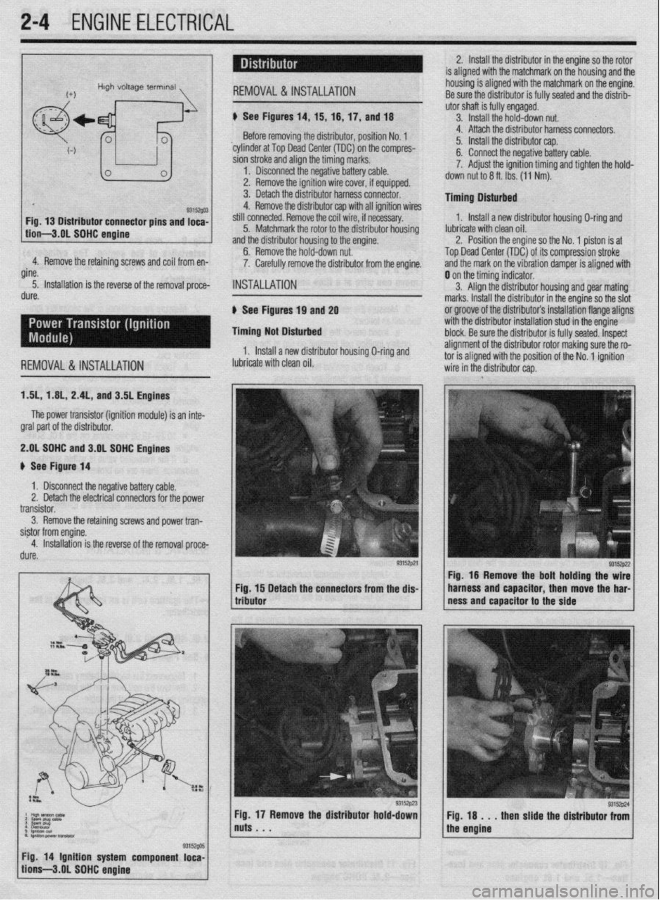
2-4 ENGINEELECTRICAL
2. Install the distributor in the engine so the rotor
is aligned with the matchmark on the housing and the
housing is aligned with the matchmark on the engine.
4.‘ Remove the retaining screws and coil from en-
gine.
5. Installation is the reverse of the removal proce-
dure. Before removing the distributor, position No. 1
‘cylinder at Top Dead Center (TDC) on the compres-
sion stroke and align the timing marks.
1. Disconnect the negative battery cable.
2. Remove the ignition wire cover, if equipped.
3. Detach the distributor harness connector.
4. Remove the distributor cap with all ignition wires
still connected. Remove the coil wire, if necessary.
5. Matchmark the rotor to the distributor housing
and the distributor housing to the engine.
6. Remove the hold-down nut.
7. Carefully remove the distributor from the engine.
INSTALLATION
6 See Figures 19 and 2g
Timing Not Disturbed
1, Install a new distributor housing O-ring and 4. Attach the distributor harness connectors.
5. Install the distributor cap.
6. Connect the negative battery cable.
7. Adjust the ignition timing and tighten the hold-
down nut to 6 ft. Ibs. (11 Nm).
Timing Dlsturbed
1. Install a new distributor housing O-ring and
lubricate with clean oil.
2. Position the engine so the No. 1 piston is at
Top Dead Center (TDC) of its compression stroke
and the mark on the vibration damper is aligned with
REMOVALS& INSTALLATION lubricate with clean oil. 0 on the timing indicator.
3. Align the distributor housing and gear mating
marks. Install the distributor in the engine so the slot
or groove of the distributor’s installation flange aligns
with the distributor installation stud in the engine
block. Be sure the distributor is fully seated. Inspect
alignment of the distributor rotor making sure the ro- tnr ic dinnnd with thn qn,c$nn of the Nn innitinn
ISL, 1 AIL, 2.4L, and 3.5L Engines
The power transistor (ignition module) is an inte-
gral part of the distributor.
2.gL SDHC and 3.OL SOHC Engines
# See Figure 14
1 x Disconnect the negative battery cable.
Remove the retaining screws and power tran-
Detach the connectors from the dis- Fig. 16 Remove the bolt holding the wire
harness and capacitor, then move the har-
ness and capacitor to the side
Fig. 18 . . . then slide the distributor from
the engine
/ tion’s-3.gL SOHC engine g3is~@ 1 Fig 14 Ignition system component loca-
Page 52 of 408
ENGlNEELECTRliAL 2-5
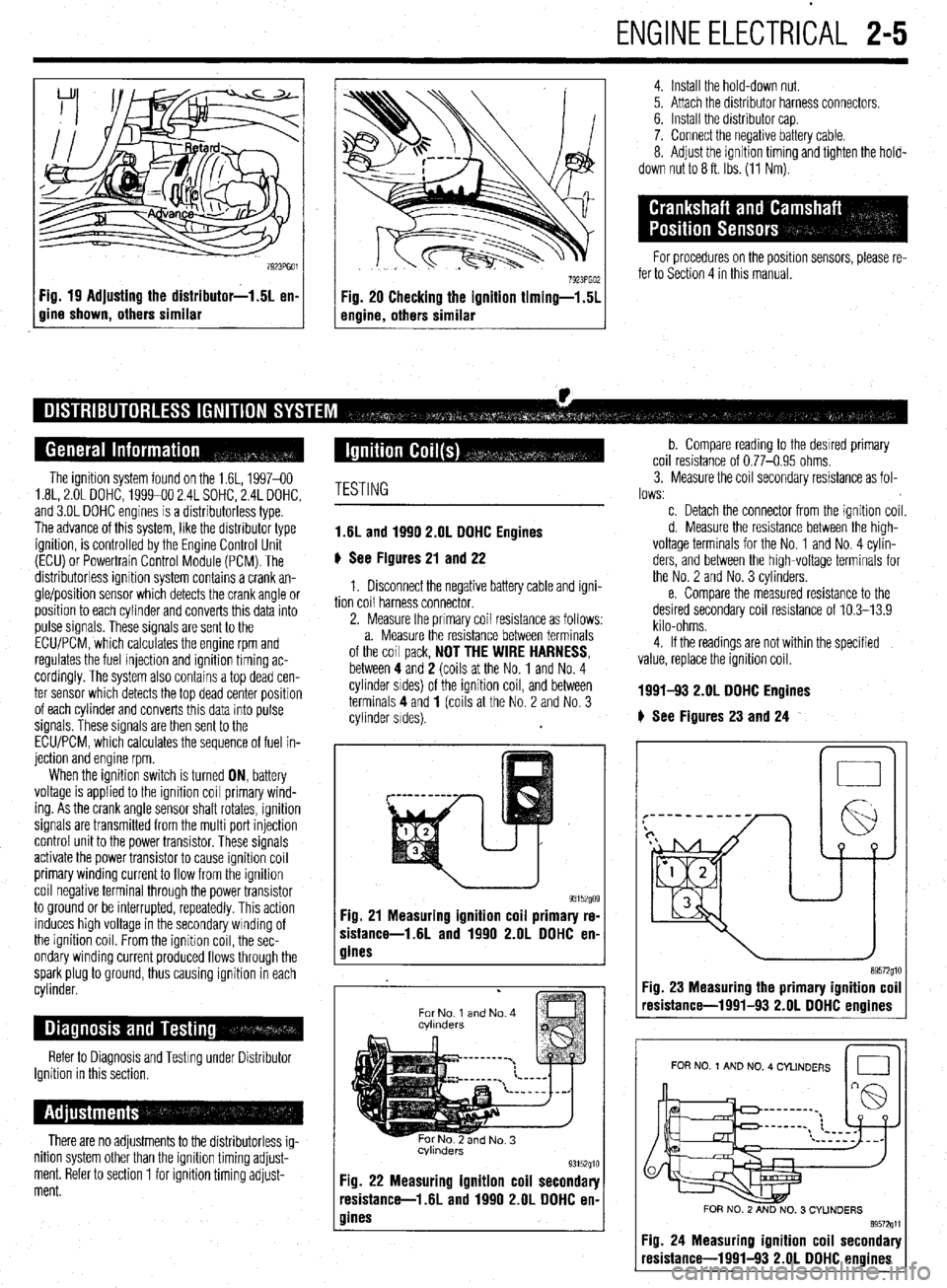
Fig. 19 Adjusting the distributor-1.5L en-
gine shown, others similar
4. Install the hold-down nut.
5. Attach the distributor harness connectors.
6. Install the distributor cap.
7. Connect the negative battery cable.
8. Adjust the ignition timing and tighten the hold-
down nut to 8 ft. Ibs. (11 Nm).
For procedures on the position sensors, please re-
fer to Section 4 in this manual.
The ignition system found on the 1.6L, 1997-60
1.8L, 2.OL DOHC, 1999-00 2.4L SOHC, 2.4L DOHC,
and 3.OL DOHC engines is a distributorless type.
The advance of this system, like the distributor type
ignition, is controlled by the Engine Control Unit
(ECU) or Powertrain Control Module (PCM). The
distributorless ignition system contains a crank an-
gle/position sensor which detects the crank angle or
position to each cylinder and converts this data into
pulse signals. These signals are sent to the
ECLVPCM, which calculates the engine rpm and
regulates the fuel injection and ignition timing ac-
cordingly. The system also contains a top dead cen-
ter sensor which detects the top dead center position
of each cylinder and converts this data into pulse
signals. These signals are then sent to the
ECU/PCM, which calculates the sequence of fuel in-
jection and engine rpm.
When the ignition switch is turned ON, battery
voltage is applied to the ignition coil primary wind-
ing. As the crank angle sensor shaft rotates, ignition
signals are transmitted from the multi port injection
control unit to the power transistor. These signals
activate the power transistor to cause ignition coil
primary winding current to flow from the ignition
coil negative terminal through the power transistor
to ground or be interrupted, repeatedly. This action
induces high voltage in the secondary winding of
the ignition coil. From the ignitron coil, the sec-
ondary winding current produced flows through the
spark plug to ground, thus causing ignition in each
cylinder.
Refer to Diagnosis and Testing under Distributor
Ignition in this section,
There are no adjustments to the distributorless ig-
nition system other than the ignition timing adjust-
ment. Refer to section 1 for ignition timing adjust-
ment.
TESTING
1.6L and 1990 2.OL DOHC Engines
6 See Figures 21 and 22
1. Disconnect the negative battery cable and igni-
tion coil harness connector.
2. Measure the primary coil resistance as follows:
a. Measure the resistance between terminals
of the coil pack,
NOT THE WIRE HARNESS, between 4 and 2 (coils at the No. 1 and No. 4
cylinder srdes) of the ignition coil, and between
terminals 4 and
1 (coils at the No. 2 and No. 3
cylinder sides).
93152go9 Fig. 21 Measuring ignition coil primary re-
sistance-1.6L and 1990 2.OL DDHC en-
gines
.
For No 1 and No. 4
cvlmders
Fig. 22 Measuring ignition coil secondary
resistance-l .6L and 1990 2.OL DOHC en-
gines
b. Compare reading to the desrred primary
coil resistance of 0.77-0.95 ohms.
3. Measure the coil secondary resistance as fol-
lows:
c. Detach the connector from the ignition coil.
d. Measure the resistance between the high-
voltage terminals for the No. 1 and No. 4 cylin-
ders, and between the high-voltage terminals for
the No. 2 and No. 3 cylinders.
e. Compare the measured resistance to the
desired secondary coil resistance of 10.3-13.9
kilo-ohms.
4. If the readings are not within the specified
value, replace the ignition coil.
1991-!I3 2.OL DDHC Engines
# See Figures 23 and 24
n 0
Fig. 23 Measuring the primary ignition coil
resistance-1991-93 2.OL DOHC enoines
I I
FOR NO 1 AND NO. 4 CYLINDERS
Id
FOR NO. 2 AND NO. 3 CYUNDERS
89572611
Fig. 24 Measuring ignition coil secondary
resistance-1991-93 2.OL DOHC engines
Page 53 of 408
2-6 ENGINEELECTRICAL
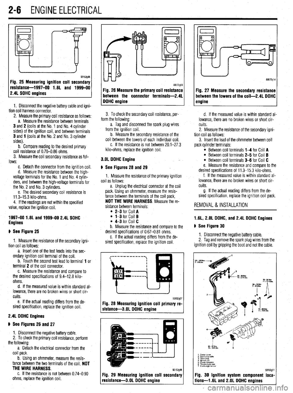
Fig. 26 Measuring ignition coil secondary
resistance-1997-00 1.8L and 1994-00
2.4L SOHC engines
1. Disconnect the negative battery cable and igni-
tion coil harness connector. 89572914
89572g13
Fig. 28 Measure the primary coil resistance Fig. 27 Measure the secondary resistance
between the connector terminals-2.4L between the towers of the coil-2.4L DOHC
DOHC enaine engine
3. To check the secondary coil resistance, per-
. .
term the tollowmg:
a. Tag and disconnect the spark plug wires
from the ignition coil.
b. Measure the secondary resistance of the
coil between the towers of each individual coil.
c. If the resistance is not between 20.1-27.3
kilo-ohms, replace the ignition coil. 2. Measure the primary coil resistance as follows:
a. Measure the resistance between terminals
3 and 2 (coils at the No. 1 and No. 4 cylinder
sides) of the ignition coil, and between terminals
3 and 1 (coils at the No. 2 and No. 3 cylinder
sides).
b. Compare reading to the desired primary
coil resistance of 0.70-0.86 ohms.
3. Measure the coil secondary resistance as fol-
lows: 3.OL DOHC Engine
c. Detach the connector from the ignition coil.
d. Measure the resistance between the high-
voltage terminals for the No. 1 and No. 4 cylin-
ders, and between the high-voltage terminals for
the No. 2 and No. 3 cylinders.
e. The desired secondary coil resistance is
11.3-15.3 kilo-ohms.
4. If the readings are not within the specified
value, replace the ignition coil.
1997-00 1.8L and 1999-00 2.4L SOHC
Engines
+ See Figure 25 6 See Figures 28 and 29
1. Measure the resistance of the primary ignition
coil as follows:
a. Unplug the electrical connector at the coil
pack. Using an ohmmeter, measure the resis-
tance between the terminals of the coil pack,
NOT THE WIRE HARNESS. Measure the re-
sistance between terminals:
l 2-3 for Coil A l l-3 for Coil B l 4-3 for Coil C
b. Measure the resistance and compare to the
desired specifications of 0.67-0.81 ohms.
1. Measure the resistance of the secondarv iani-
tion coil as follows: , -
a. Insert one of the test leads into the sec-
ondary ignition coil terminal of the coil.
b. Touch the second test lead to terminal 1 or
terminal 2 of the coil connector.
c. Measure the resistance and compare to
the desired specifications of 9.4-12.8 kilo-
ohms.
d. If the measured value is within standard al-
lowance, there are no broken wires or short cir-
cuits.
e. If the actual reading differs from the de-
sired specification, replace the ignition coil.
2.4L DDHC Engines
# See Figures 26 and 27
1. Disconnect the negative battery cable.
2. To check the primary coil resistance, perform
the following:
a. Detach the electrical connector from the
coil pack.
b. Using an ohmmeter, measure the resis-
tance between the two terminals of the coil, NOT
THE WIRE HARNESS.
c. If the resistance is not between 0.74-0.90
ohms, replace the ignition coil. c. If the actual reading differs from the de-
sired specification, replace the ignition coil.
Fig. 28 Measuring ignition coil primary re-
sistance-3.01 DOHC engine
Fig. 29 Measuring ignition coil secondary
resistance-3.01 DOHC enaine d. If the measured value is within standard al-
lowance, there are no broken wires or short cir-
cuits.
2. Measure the resistance of the secondary igni-
tion coil as follows:
3. Insert the lead of the ohmmeter between coil
pack cylinder terminals:
l Between coil terminals l-4 for Co11 A l Between coil terminals 2-5 for Coil B l Between coil terminals 3-6 for Coil C
e. Measure the resistance and compare to the
desired specifications of 11.3-l 5.3 kilo-ohms.
f. If the measured value is within standard al-
lowance, there are no broken wires or short cir-
cuits.
g. If the actual reading differs from the de-
sired specification, replace the ignition coil pack.
REMOVAL&INSTALLATION
1.6L, 2.OL DOHC, and 2.4L DOHC Engines
# See Figure 30
1. Disconnect the negative battery cable.
2. Tag and remove the spark plug wires from the
ignition coil by gripping the boot and not the cable.
I
~::::L “1
I cemer Cwer
2 Scabpiwcabk
3 SPaark piug
I lgnlllancoll
5 Powertran3lrtor
6 ThrotflsDcnv*w
I Crankangle lmsm
93152g11
Fig. 30 Ignition system component loca-
lions-l .6L and 2.OL DOHC engines
Page 54 of 408
ENGINEELECTRICAL 2-7
3. Detach the electrical connectors for the COIL
4. Remove the retaining screws and coil from en-
gine.
5. Installation is the reverse of the removal proce-
dure.
1997-00 1.81 and 1994-00 2.4L Engines
) See Figure 31
1, Disconnect the negative battery cable.
2. Detach the electrical connector(s) for the
coil(s).
3. Remove the spark plug wire(s) to the compan-
ion cylinder(s).
4 Remove the coil retaining bolts and lift the coil
from the cylinder head.
5. The installation is the reverse of the removal.
3.OL DOHC Engine
# See Figure 32
1, Disconnect the negative battery cable.
2. Remove the intake manifold plenum (upper in-
take mamfold) Refer to Section 3.
3. Tag and remove the spark plug wires from the
ignition coil by gripping the boot and not the cable.
4 Detach the electrical connectors for the coil.
5. Remove the retaining screws and coil from en-
gine.
6. Installation is the reverse of the removal proce-
dure.
REMOVAL &INSTALLATION
1 AL, 2.01 DOHC, and 2.4L DOHC Engines
) See Figure 30
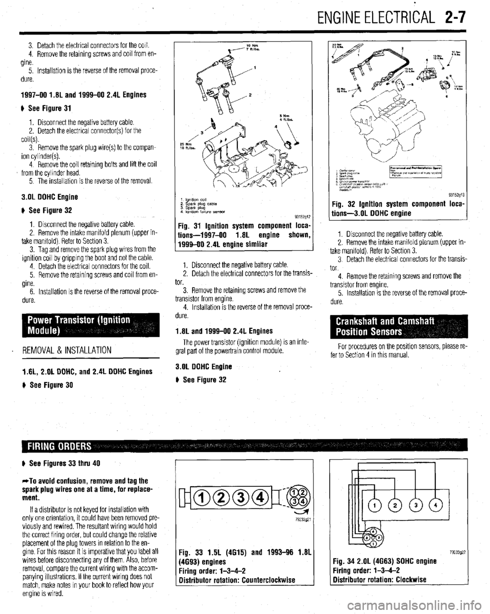
1 lgnltlo” co,,
2 sparlt plug case
3 Spark plug
4 Imltlon fatlure semm
93152g1:
Fig. 31 Ignition system component loca,
iions-1997-00 1.8L engine shown
1999-00 2.4L engine similar
1. Disconnect the negative battery cable.
2. Detach the electrical connectors for the transis-
tor.
3. Remove the retaining screws and remove the
transistor from engine.
4. Installation is the reverse of the removal proce-
dure.
1.8L and 1999-00 2.4L Engines
The power transistor (ignition module) is an inte-
gral part of the powertrain control module.
3.OL DOHC Engine
# See Figure 32
9315291 Fig. 32 Ignition system component loca,
tions-3.01 DOHC engine
1. Disconnect the negative battery cable.
2. Remove the intake manifold plenum (upper in-
take manifold). Refer to Section 3.
3 Detach the electrical connectors for the transis-
tor.
4. Remove the retaining screws and remove the
transistor from engine.
5. Installation is the reverse of the removal proce-
dure.
For procedures on the positlon sensors, please re-
fer to Section 4 in this manual.
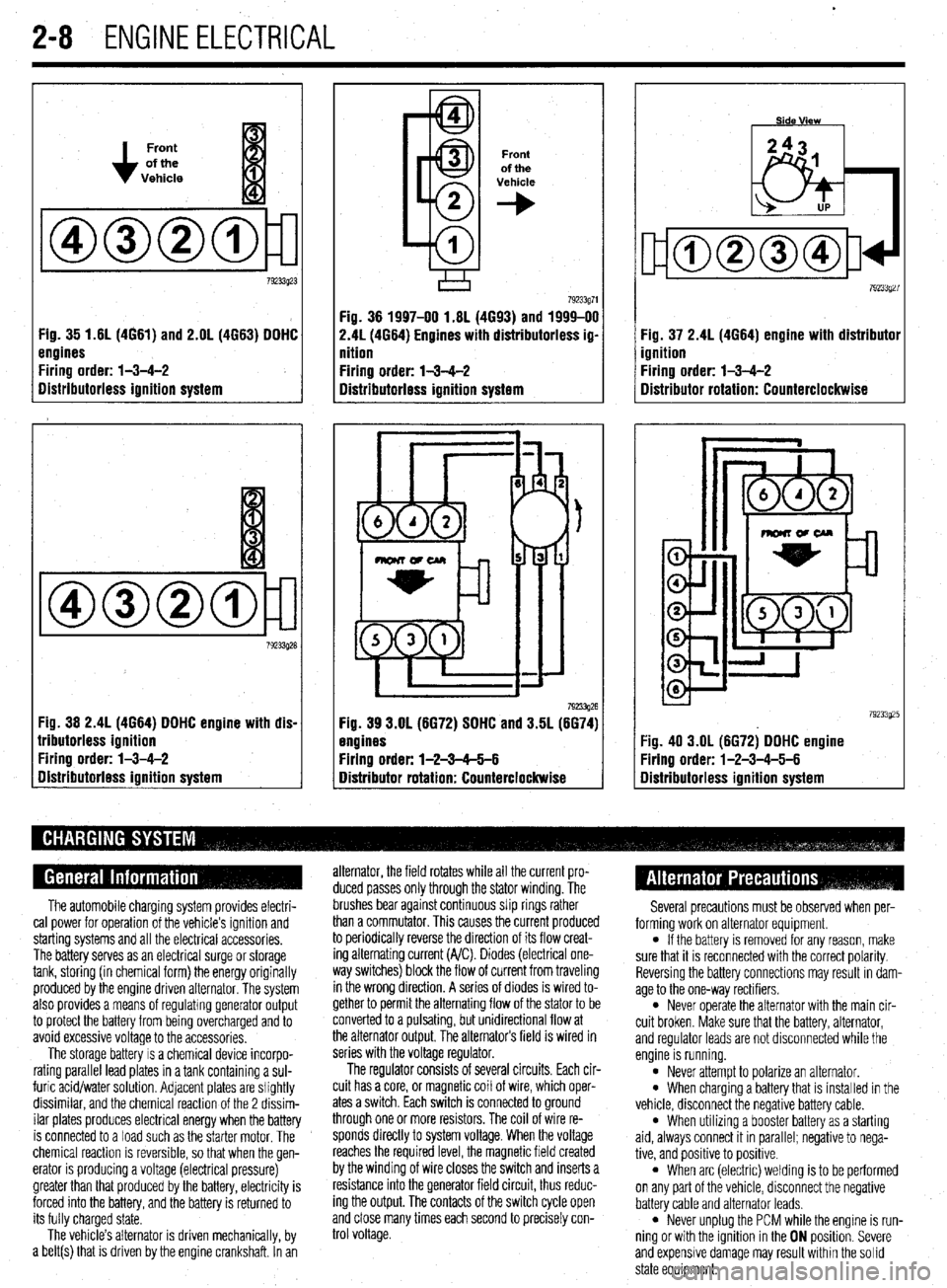
# See Figures 33 thru 40
*To avoid confusion, remove and tag the
spark plug wires one at a time, for replace-
ment.
If a distributor is not keyed for installation with
only one orientation, it could have been removed pre-
viously and rewired. The resultant wiring would hold
the correct firing order, but could change the relative
placement of the plug towers in relation to the en-
gine. For this reason it is imperative that you label all
wires before disconnecting any of them. Also, before
removal, compare the current wiring with the accom-
panying illustrations. If the current wiring does not
match, make notes in your book to reflect how your
engine is wired.
ujamm-p:@
79233921
Fig. 33 1.5L (4615) and 1993-96 1.81
(4693) engines
Firing order: l-3-4-2
Distributor rotation: Counterclockwise 7923392: :ig. 34 2.OL (4663) SOHC engine
‘iring order: l-3-4-2
Distributor rotation: Clockwise
Page 55 of 408
.
2-8 ENGINEELECTRICAL
Front
of the
Vehicle
Fig. 35 1.61(4661) and 2.OL (4663) DDHC
engines
Firing order: l-3-4-2
Distributorless ignition system
Fig. 36 2.4L (4664) DDHC engine with dis-
lributorless ignition
Firing order: l-3-4-2
gistributorless ignition system
Front
of the
Vehicle
+
Fig. 36 1997-00 1.6L (4693) and 1999-00
2.41(4664) Engines with distributorless ig-
nition
Firing order: l-3-4-2
Distributorless ignition system
792!33g26 Fig. 39 3.OL (6672) SDHC and 3.5L (6674)
engines
Firing order: l-2-3-65-6
Distributor rotation: Counterclockwise Fig. 37 2.4L (4664) engine with distributor
ignition
Firing order: l-3-4-2
Distributor rotation: Counterclockwise
:ig. 40 3.OL (6672) DDHC engine
Yring order: l-2-3-4-5-6
Iistributorless ignition system
The automobile charging system provides electri-
cal power for operation of the vehicle’s ignition and
starting systems and all the electrical accessories.
The battery serves as an electrical surge or storage
tank, storing (in chemical form) the energy originally
produced by the engine driven alternator. The system
also provides a means of regulating generator output
to protect the battery from being overcharged and to
avoid excessive voltage to the accessories.
The storage battery IS a chemical device incorpo-
rating parallel lead plates in a tank containing a sul-
furic acid/water solution. Adjacent plates are slightly
dissimilar, and the chemical reaction of the 2 dissim-
ilar plates produces electrical energy when the battery
is connected to a load such as the starter motor. The
chemical reaction is reversible, so that when the gen-
erator IS producing a voltage (electrical pressure)
greater than that produced by the battery, electricity is
forced into the battery, and the battery is returned to
its fully charged state.
The vehicle’s alternator is driven mechanically, by
a belt(s) that is driven by the engine crankshaft. In an alternator, the field rotates while all the current pro-
duced passes only through the stator winding. The
brushes bear against continuous slip rings rather
than a commutator. This causes the current produced
to periodically reverse the direction of its flow creat-
ing alternating current (A/C). Diodes (electrical one-
way switches) block the flow of current from traveling
in the wrong direction. A series of diodes is wired to-
gether to permit the alternating flow of the stator to be
converted to a pulsating, but unidirectional flow at
the alternator output, The alternators field is wired in
series with the voltage regulator.
The regulator consists of several circuits. Each cir-
cuit has a core, or magnetic coil of wire, which oper-
ates a switch. Each switch is connected to ground
through one or more resistors. The coil of wire re-
sponds directly to system voltage. When the voltage
reaches the required level, the magnetic field created
by the winding of wire closes the switch and inserts a
resistance into the generator field circuit, thus reduc-
ing the output. The contacts of the switch cycle open
and close many times each second to precisely con-
trol voltage. Several precautions must be observed when per-
forming work on alternator equipment.
l If the battery is removed for any reason, make
sure that it is reconnected with the correct polarity.
Reversing the battery connections may result In dam-
age to the one-way rectifiers.
l Never operate the alternator with the main cir-
cuit broken. Make sure that the battery, alternator,
and regulator leads are not disconnected while the
engine is running.
l Never attempt to polarize an alternator. l When charging a battery that is installed in the
vehicle, disconnect the negative battery cable.
l When utilizing a booster battery as a starting
aid, always connect it in parallel; negatrve to nega-
tive, and positive to positrve.
l When arc (electric) welding is to be performed
on any part of the vehicle, disconnect the negative
battery cable and alternator leads.
l Never unplug the PCM while the engine is run-
ning or with the ignition in the ON position. Severe
and expensive damage may result within the solid
state equipment.
Page 56 of 408
ENGlNEELECTRldAL 2-9
TESTING
Voltage Test able for use by customers. An alternator
bench test is the most definitive way to de-
termine the condition of your alternator.
REMOVAL&INSTALLATION
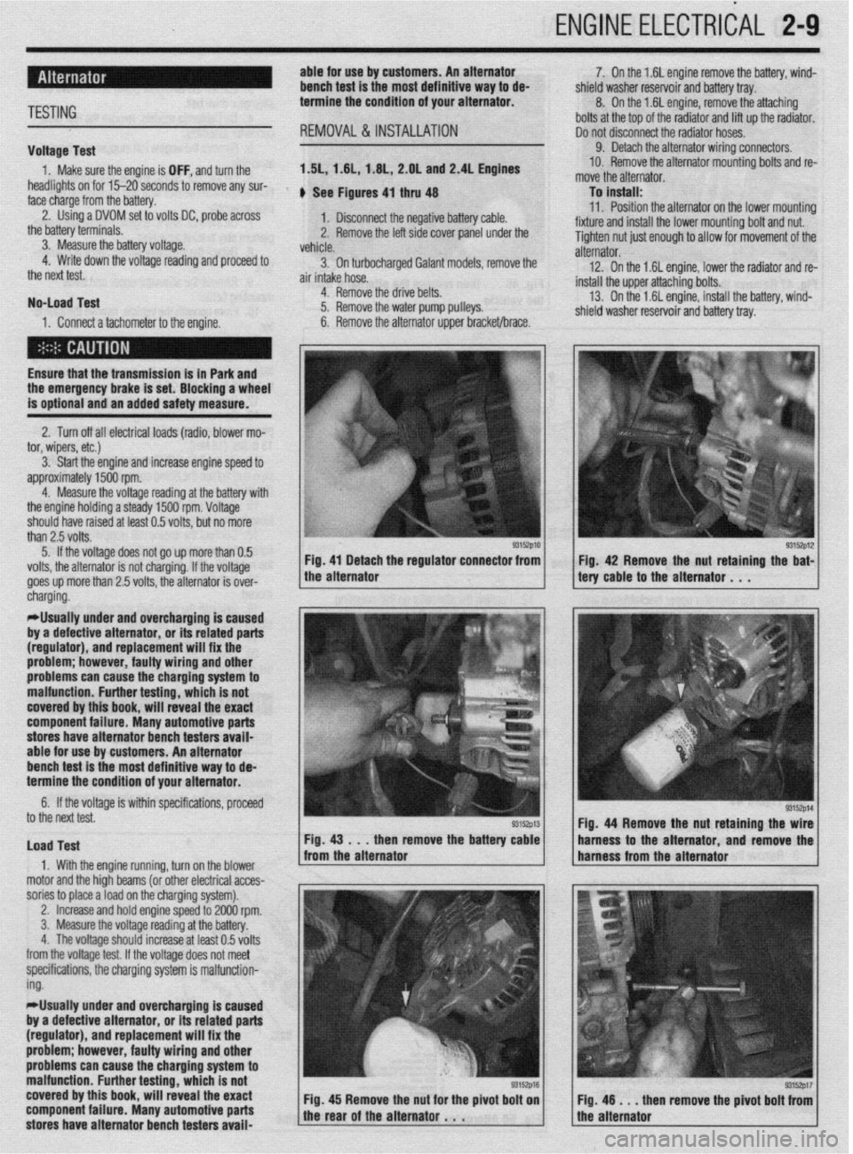
1. Make sure the engine is OFF, and turn the 1.51,1.61, 1.6L, 2.OL and 2.4L Engines
headlights on for 15-20 seconds to remove any sur-
face charge from the battery. , See Figures 4, thru 48
2. Using a DVOM set to volts DC, probe across
1. Disconnect the negative battery cable.
the battery terminals.
3. Measure the battery voltage. 2. Remove the left side cover panel under the
vehicle.
4. Write down the voltage reading and proceed to
3. On turbocharaed Galant models, remove the
the next test.
air intake hose. -
No-load Test
1. Connect a tachometer to the engine. 4. Remove the drive belts.
5. Remove the water pump pulleys.
6. Remove the alternator upper bracket/brace.
Ensure that the transmission
is in Park and the emergency brake is set. Blocking a wheel
is optional and an added safety measure.
2. Turn off all electrical loads (radio, blower mo-
tor, wipers, etc.)
3. Start the engine and increase engine speed to
approximately 1500 rpm.
4. Measure the voltage reading at the battery with
the engine holding a steady 1500 rpm. Voltage
should have raised at least 0.5 volts, but no more
than 2.5 volts.
5. If the voltage does not go up more than 0.5
volts, the alternator is not charging. If the voltage
goes up more than 2.5 volts, the alternator is over-
* 7. On the 1.6L engine remove the battery, wind-
shield washer reservoir and battery tray.
8. On the 1.6L engine, remove the attaching
bolts at the top of the radiator and lift up the radiator.
Do not disconnect the radiator hoses.
9. Detach the alternator wiring connectors.
10. Remove the alternator mounting bolts and re-
move the alternator.
To install:
11. Position the alternator on the lower mountina
fixture and install the lower mounting bolt and nut. U
Tighten nut just enough to allow for movement of the
alternator.
12. On the 1.6L engine, lower the radiator and re-
install the upper attaching bolts.
13. On the 1.6L engine, install the battery, wind-
shield washer reservoir and battery tray.
/ tery cable to the alternator . , . 93152p12 Fig 42 Remove the nut retaining the bat-
cnargmg.
*Usually under and overcharging is‘caused
by a defective alternator, or its related parts
(regulator), and replacement will fix the
problem; however, faulty wiring and other
problems can
cause the charging system to
malfunction. Further testing, which is not
covered by this book, will reveal the exact
component failure. Many automotive parts
stores have alternator bench testers avaii-
able for use by customers. An alternator
bench test is the most definitive way to de-
termine the condition of your alternator.
6. If the voltage is within specifications, proceeU
to the next test.
Load Test
1. With the engine running, turn on the blower
motor and the hioh beams (or other electrical acces-
sories to place aioad on the charging system). Fig. 44 Remove the nut retaining the
then remove the batte harness to the alternator and remov
,
2. Increase and hold engine speed to 2000 rpm.
3. Measure the voltage reading at the battery.
4. The voltage should increase at least 0.5 volts
from the voltage test. If the voltage does not meet
specifications, the charging system is malfunction-
ing.
*Usually under and overcharging is caused
by a defective alternator, or its related parts
(regulator), and replacement will fix the
problem; however, faulty wiring and other
problems can cause the charging system to
malfunction. Further testing, which is not
covered by this book, will reveal the exact
component failure. Many automotive parts
stores have alternator bench testers avaii-
93152p17 en remove the pivot bolt from
Page 57 of 408
.
2-10 ENGINEELECTRICAL 1
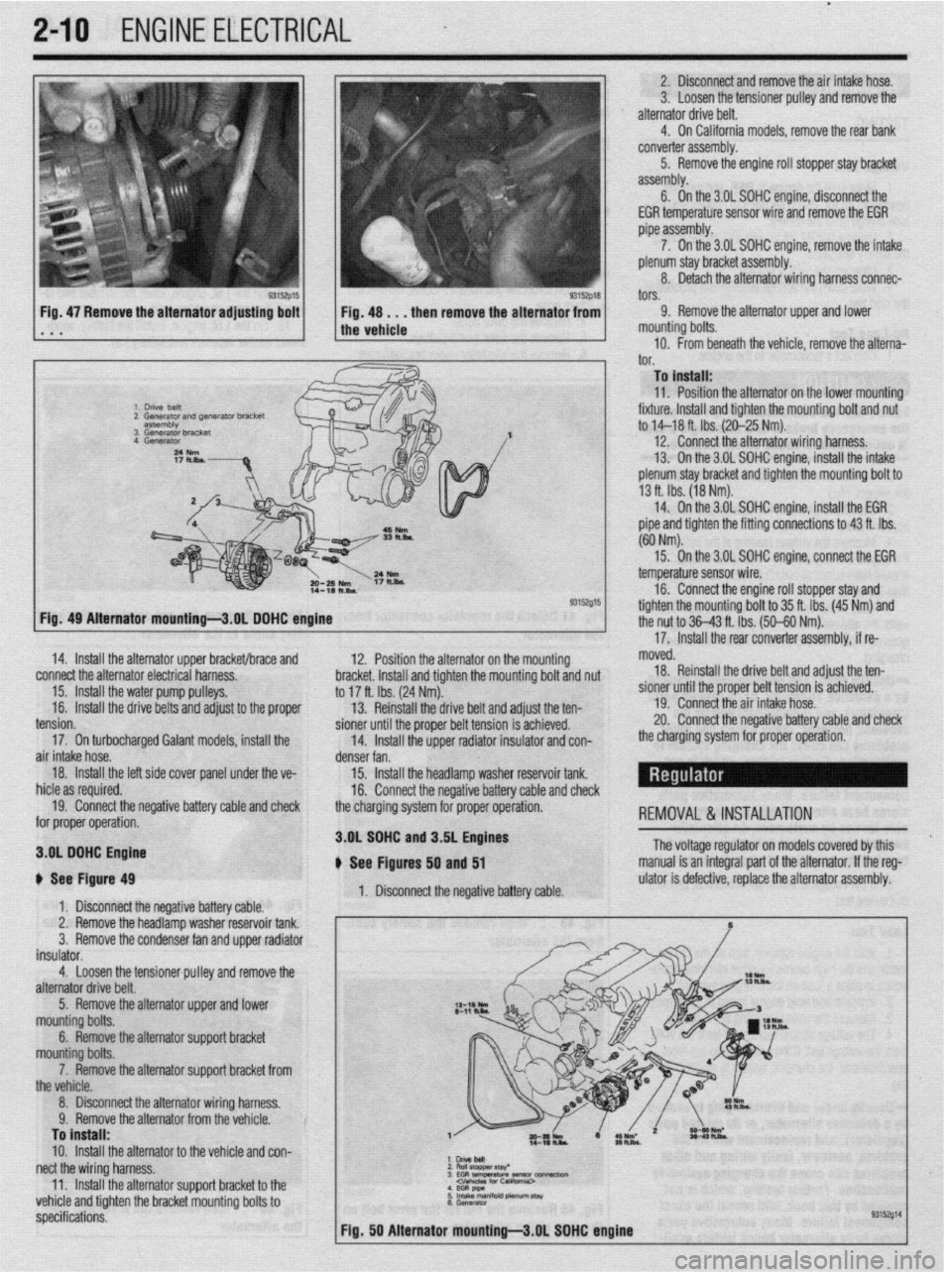
2. Disconnect and remove the air intake hose.
3. Loosen the tensioner pulley and remove the
alternator drive belt.
4. On California models, remove the rear bank
converter assembly.
5. Remove the engine roll stopper stay bracket
assembly.
6. On the 3.OL SDHC engine, disconneCt the
EGR temperature sensor wire and remove the EGR
pipe assembly.
7. On the 3.OL SOHC engine, remove the intake
plenum stay bracket assembly.
8. Detach the alternator wiring harness connec-
tors.
Fig, 47 Remove the alternator adjusting bolt
. a a 9. Remove the alternator upper and lower
mounting bolts.
10. From beneath the vehicle, remove the alterna-‘
I^”
._. To install:
11. Position the alternator on the lower mountino
fixture. Install and tighten the mounting bolt and nu<
to M-18 ft. Ibs. (20-25 Nm).
12. Connect the alternator wiring harness.
13. On the 3.OL SOHC engine, install the intake
plenum stay bracket and tighten the mounting bolt to
13 ft. Ibs. (18 Nm).
14. On the 3.OL SOHC engine, install the EGR
pipe and tighten the fitting connections to 43 ft. Ibs.
(60 Nm).
93152015
12. Position the alternator on the mour
sting hmrkd lnrtnll rmr( tinhtnn thn mm dim L VIUVI,VL. lllcllUll Ully llylllvll LltU ,,tvuln,,ly volt and nut
to 17 ft. Ibs. (24 Nm).
13. Reinstall the drive belt and adjust the ten-
pinnor fmtil the nmnor hdt toncinn ic art-:--~
15. On the 3.OL SOHC enoine. connect the EGR
- temperature sensor wire.
16. Connect the engine roll stopper stay and
tighten the mountina bolt to 35 ft. Ibs. (45 Nm) and
the nut to 36-43 ft. Tbs. (50-60 Nm).
’
17. Install the rear converter assembly, if re- Fia. 49 Alternator mountinu-3.0L DOHC enoine
14. Install the alternator upper bracket/brace and
connect the alternator electrical harness.
15. Install the water pump pulleys.
16.
Install the drive belts and adjust to the proper moved.
18. Reinstall the drive belt and adjust the ten-
sioner until the proper belt tension is achieved.
19. Connect the air intake hose.
20. Connect the neoativa hatterv rzahle and check -_. -_. __. _. _=-__
_ _-.._. , ___ _ _. _ _ _ _
the charoina system for orooer ooeration. - - _ -rr- -- - I Ull” Yvll air intake hose.
denser fan.
18.
Install the left side cover panel unde
r the ve-
15. Install the headlamp washer reservoir tank.
hid@ zx ran~kwl 1IIVI” YY ‘“~“““Y.
16. Connect the negative battery cable and check
19. Connect the negative battery cable and check
the charging svstem for proper operation.
-,-.- for proper operation. REMOVAL &INSTALLATION
3.OL SOHC n C, n---I_--
3.OL DOHC Engine
i fhs Itin** tension.
17. On turbocharged Galant models, install the
b See Figure 49
1. Disconnect the negative battery cable.
2. Remove the headlamp washer reservoir tank.
3.
Remove the condenser fan and upper radiator
insulator.
4.
Loosen the tensioner pulley and remove the
alternator drive belt. and J.DL engines
, - , lyures 50 and 51
1. Disconnect the negative battery cable. The voltage regulator on models covered by this
manual is an integral part of the alternator. If the reg-
ulator is defective, replace the alternator assembly.
5. Remove the alternator upper and lower
mounting bolts.
6. Remove the alternator support bracket
mn~lntinn h&c
_ _ _ _ -. ._ ,_._
--TT-.. -.--..-. ..-...
the vehicle.
8. Disconnect the alternator wiring harness.
Q Romnm thn slternatnr frnm thn mhirln V. llYlll”“Y LI1”“I~Y1IIU,“I II”,,, Lll” ,“,,,“,“. To install:
10.
Install the alternator to the vehicle and con-
nect the wiring harness. :z
E$llaf 3EG RtEWtiW~-~ 11
Install the alternatnr wnnnrt hrxket tn thp .._. -.. .._ - .._..._._.
--rT-.. -.--..-. .- I.._ .P _ vehicle and tighten the bracket mounting bolts to
specifications.
Page 58 of 408
ENGINE ELECTRICAL 2-11
l.unVeMlil(GSflWtWJ
2.Gwwator harness con- connectk,,,
3. Engme OS, level d,pst,&
4 Generator
Fig. 51 Alternator mounting -3.51 engine
The starting system includes the battery, starter
motor, solenoid, ignition switch, circuit protection
and wiring connecting the components. An inhibitor
switch located in the park/neutral safety switch or
Transmission Range (TR) sensor is included in the
starting system to prevent the vehicle from being
started with the vehicle in gear.
When the ignition key is turned to the START po-
sition, current flows and energizes the starters sole-
noid coil. The solenoid plunger and clutch shift lever
are activated and the clutch pinion engages the ring
gear on the flywheel. The switch contacts close and
the starter cranks the engine until it starts.
To prevent damage caused by excessive starter ar-
mature rotation when the engine starts, the starter in-
corporates an over-running clutch in the pinion gear. 2. Connect a voltmeter between the positive ter-
minal of the battery and the starter B+ circuit.
3. Turn the ignition key to the START position
and note the voltage on the meter.
4. If voltage reads 0.5 volts or more, there is high
resistance in the starter cables or the cable ground,
repair as necessary. If the voltage reading is ok pro-
teed to the next step.
5. Connect a voltmeter between the positive ter-
minal of the battery and the starter M circuit,
6. Turn the ignition key to the START position
and note the voltage on the meter.
7. If voltage reads 0.5 volts or more, there is high
resistance in the starter. Repair or replace the starter
as necessary.
*Many automotive parts stores have starter
bench testers available for use by customers.
A starter bench test is the most definitive
way to determine the condition of your
starter. 3. Remove the resonator retaining nuts and re-
move the air intake hose and resonator assembly as
required.
rllse care when removing the air cleaner
cover because the air-flow sensor is attached
and is a sensitive component.
4. If equipped with Active-ECS suspension, re-
move the air compressor as follows:
a. Detach the two electrical connectors, from
the compressor.
b. Disconnect the air line at the compressor.
c. Remove the three mounting bolts, securing
the compressor to the chassis.
5. Raise the vehicle and support safely.
6. Remove the engine undercover.
7. Remove the heat shield from beneath the in-
take manifold on the 1.5L engine.
8. If necessary, detach the speedometer cable
connector at the transaxle end.
9. Detach the starter motor electrical connac-
TESTING
Voltage Drop Test
*The battery must be in good condition and
fully charged prior to performing this test. REMOVAL&INSTALLATION
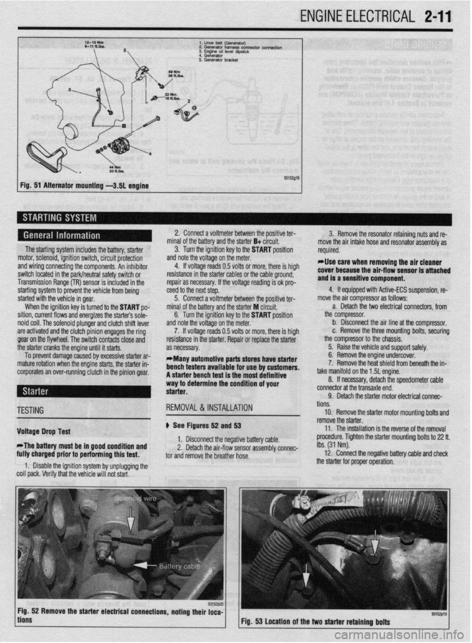
# See Figures 52 and 53
1. Disconnect the negative battery cable.
2. Detach the air-flow sensor assembly connec-
tor and remove the breather hose.
1. Disable the ignition system by unplugging the
coil pack. Verify that the vehicle will not start. tions.
10. Remove the starter motor mounting bolts and
remove the starter.
11. The installation is the reverse of the removal
procedure. Tighten the starter mounting bolts to 22 ft.
Ibs. (31 Nm).
12. Connect the negative battery cable and check
the starter for proper operation.
9315zp19 Fig. 53 Location of the two starter retaining bolts
Page 59 of 408
.
2-12 ENGINEELECTRICAL
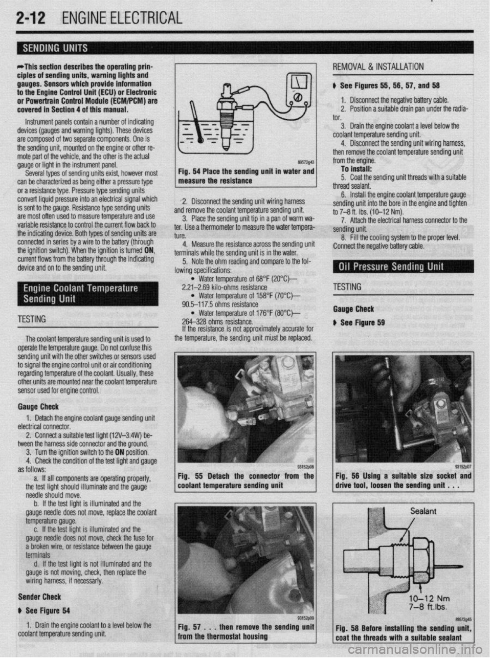
*This section describes the operating prina
ciples of sending units, warning lights and
gauges. Sensors which provide information
to the Enafne Control Unit (ECU) or Electronic
or Power&in Control Module (FCM/PCM) are
covered in Section 4 of this manual.
Instrument panels contain a number of indicating
devices (gauges and warning lights). These devices
are composed of two separate components. One is
the sending unit, mounted on the engine or other re-
mote part of the vehicle, and the other is the actual
gauge or light in the instrument panel.
Several types of sending units exist, however most
can be characterized as being either a pressure type
or a resistance type. Pressure type sending units
convert liquid pressure into an electrical signal which
is sent to the gauge. Resistance type sending units
are most often used to measure temperature and use
variable resistance to control the current flow back to
the indicatinq device. Both types of sendinq units are
connected inseries by a wimto the batteryithiough
the ignition switch). When the ignition is turned ON,
current flows from the battery through the indicating
device and on to the sending unit.
89572$43 Fig. 54 Place the sending unit in water and
measure the resistance
2. Disconnect the sending unit wiring harness
and remove the coolant temperature sending unit.
3. Place the sending unit tip in a pan of warm wa-
ter. Use a thermometer to measure the water tempera-
tl KP
L”,“.
4. Measure the resistance across the sending uni
terminals while the sending unit is in the water.
5. Note the ohm reading and compare to the fol-
lowing specifications: i, 56, 57, and 56
1. Disconnect the negative battery cable.
2. Position a suitable drain pan under the radia-
tor.
3. Drain the engine coolant a level below the
coolant temperature sending unit.
4. Disconnect the sending unit wiring harness,
then remove the coolant temperature sending unit
from the engine.
To install:
5. Coat the sending unit threads with a suitable
thread sealant.
6. Install the engine coolant temperature gauge
sending unit into the bore in the engine and tighten
to 7-8 ft. Ibs. (10-12 Nm).
7. Attach the electrical harness connector to the
sendina unit.
8. fill the cooling system to the proper level.
:onnect the negative battery cable.
l Water temperature of 68°F (2O”C)-
2.21-2.69 kilo-ohms resistance
l Water temperature of 158°F (7O’Ck
90.5-117.5 ohms resistance
TESTING l Water temperature of 176°F (8O”C)-
264-328 ohms resistance.
The coolant temperature sendina unit is used to
operate the temperature gauge. Donot confuse this
sending unit with the other switches or sensors used
to signal the engine control unit or air conditioning
regarding temperature of the coolant. Usually, these
other units are mounted near the coolant temoerature
sensor used for engine control. If the resistance is not approximately accurate for
the temperature, the sending unit must be replaced.
Gauge Check
1. Detach the engine coolant gauge sending unit
electrical connector.
2. Connect a suitable test liaht (12V-3.4W) be-
tween the harness side connector and the around.
I
3. Turn the ignition switch to the ON position.
4. Check the condition of the test light and gauge
as follows:
a. If all components are operating properly,
the test light should illuminate and the gauge
needle should move.
b. If the test light is illuminated and the
gauge needle does not move, replace the coolant
temperature gauge.
c. If the test light is illuminated and the
gauge needle does not move, check the fuse for
a broken wire, or resistance between the gauge
terminals
d. If the test light is not illuminated and the
gauge is not moving, check, then replace the
wiring harness, if necessar!y.
Sender Check
p See Figure 64
1. Drain the engine coolant to a level below the
coolant temperature sending unit Fig. 55 Detach the connector from the
coolant temperature sending unit
'ESTING
tauga Check
See Ftgure 69
Page 60 of 408
ENGINE ELECTRlCiL 2-13
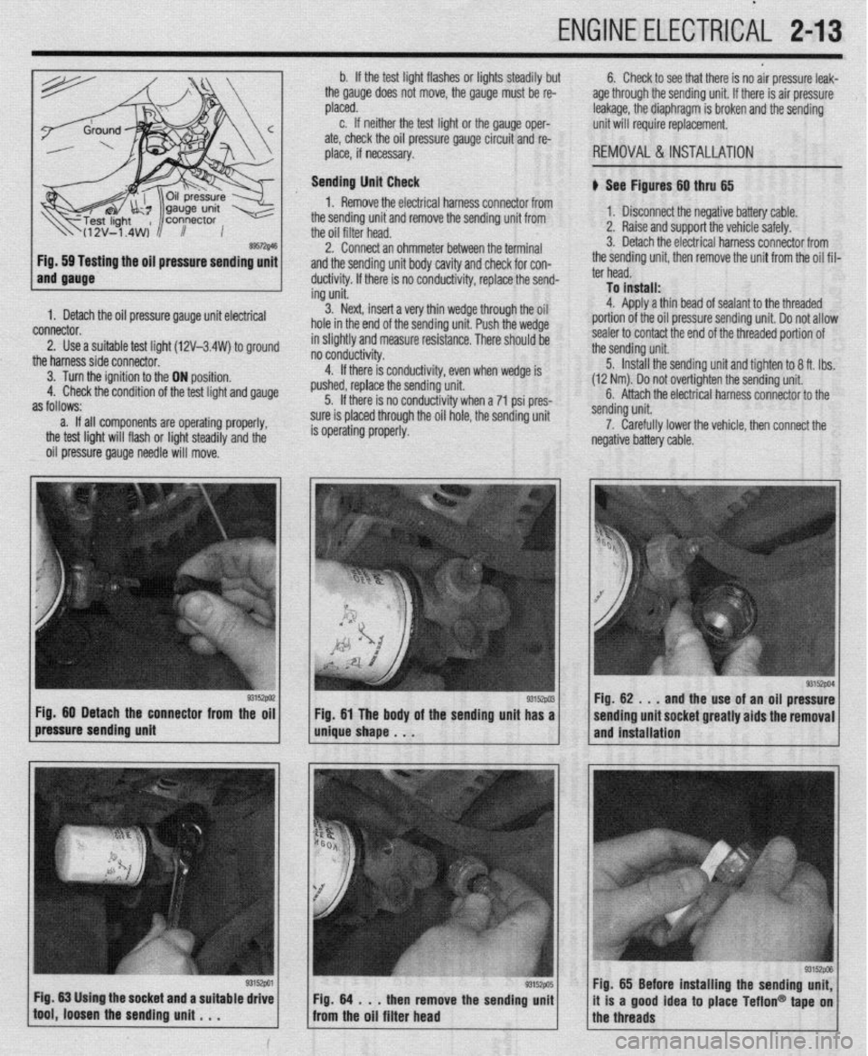
ing the oil pressure sending unit
1. Detach the oil pressure gauge unit electrical
connector.
2. Use a suitable test lioht (12V-3.4W) to around
the harnesssideconnecto~ ’ ’ -
3. Turn the ignition to the ON position.
4. Check the condition of the test light and gauge
as follows:
a. If all components are operating properly,
the test light will flash or light steadily and the
oil pressure gauge needle will move. b. If the test light flashes or lights steadily but
the gauge does not move, the gauge must be re-
placed.
c. If neither the test light or the gauge oper-
ate, check the oil pressure gauge circuit and re-
place, if necessary.
Sending Unit Check
1. Remove the electrical harness connector from
the sending unit and remove the sending unit from
the oil filter head.
2. Connect an ohmmeter between the terminal
and the sending unit body cavity and check for con-
ductivity. If there is no conductivity, replace the send-
ing unit.
3. Next, insert a very thin wedge through the oil
hole in the end of the sending unit. Push the wedge
in slightly and measure resistance. There should be
- - -- d . . . .
no conoucovey.
4. If there is conductivity, even when wedge is
pushed, replace the sending unit.
5. If there is no conductivity when a 71 psi pres-
sure is placed through the oil hole, the sending unit
is operating properly. 6. Check to see that there is no air pressure leak-
age through the sending unit. If there is air pressure
leakage, the diaphragm is broken and the sending
unit will require replacement.
REMOVAL &INSTALLATION
b See Figures 60 thru 65
1. Disconnect the negative battery cable.
2. Raise and support the vehicle safely.
3. Detach the electrical harness connector from
the sending unit, then remove the unit from the oil fil-
ter head.
To install:
4. Aoolv a thin bead of sealant to the threaded
portion of the oil pressure sending unit. Do not allow
sealer to contact the end of the threaded portion of
the sending unit.
5. Install the sending unit and tighten to 8 ft. tbs.
(12 Nm). Do not over-tighten the sending unit.
6. Attach the electrical harness connector to the
/pressure sending unit g3’9wi / m&e shape . . . Fig 60 Detach the connector from the oil
g3152w Fig 61 The body of the sending unit has a sending unit.
7. Carefully lower the vehicle, then connect the
negative battery cable.
93152PM Fig. 62 . , .
and the use of an oil pressure
sending unit socket greatly aids the removal
and installation
Fig. 65 Before installing the sending unit,
it is a good idea to place Teflon@ tape on
the threads