MITSUBISHI ECLIPSE 1990 Service Manual
Manufacturer: MITSUBISHI, Model Year: 1990, Model line: ECLIPSE, Model: MITSUBISHI ECLIPSE 1990Pages: 391, PDF Size: 15.27 MB
Page 201 of 391
.-_. -
17-8REAR SUSPENSION <4WD> - Geneal information
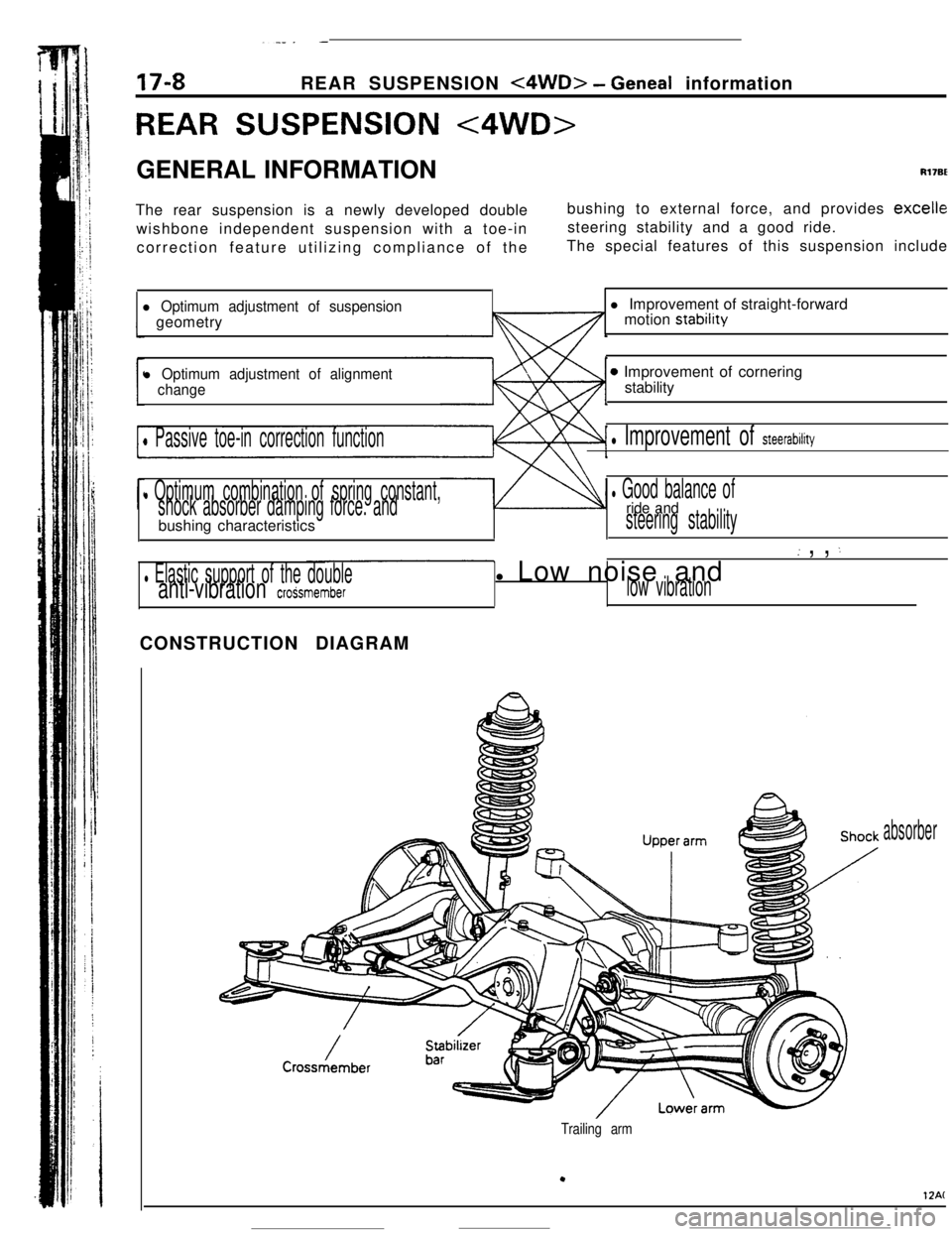
REAR SUSPENSION <4WD>GENERAL INFORMATION
Rl7BEThe rear suspension is a newly developed double
wishbone independent suspension with a toe-in
correction feature utilizing compliance of thebushing to external force, and provides
excellesteering stability and a good ride.
The special features of this suspension include
l Optimum adjustment of suspensiongeometry
l Optimum adjustment of alignment
change
0 Passive toe-in correction function
l Optimum combination of spring constant,
shock absorber damping force. andbushing characteristics
l Elastic support of the doubleanti-vibration croSsmemberl Improvement of straight-forward
motion stability
0 Improvement of cornering
stability
l Improvement of steerability
l Good balance ofride andsteering stability
( , , :l Low noise and
low vibrationCONSTRUCTION DIAGRAM
absorber
Trailing arm
.
12AC
Page 202 of 391
_ -. ..__ .-
REAR SUSPENSION
<4WD> - Geneal (nformation
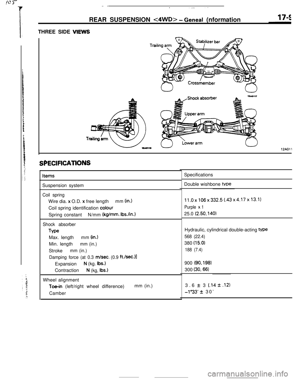
THREE SIDE VIEWS
Trailil
12AOll
SPECiFiCATiONSItems
Suspension system
Coil springWire dia. x O.D.
x free lengthmm (in.)Coil spring identification
colourSpring constantN/mm
(kg/mm. Ibs.An.1
Shock absorberType
Max. lengthmm
(in.)Min. length
mm (in.)Stroke
mm (in.)
Damping force (at 0.3
m/set. (0.9 ft./sec.)l
Expansion
N (kg. Ibs.)Contraction
N (kg, Ibs.)Wheel alignment
Toe-in (left/right wheel difference)mm (in.)
CamberSpecifications
Double wishbone tvpe
11.0x106x332.5(.43x4.17x13.1)
Purple x 125.0
(2.50, 140)Hydraulic, cylindrical double-acting
We
568 (22.4)380
(15.0)
188 (7.4)900
(90. 198)300
(30.66)3.6
f 3 (.14 2 .I21
-1”33’ + 30’
Page 203 of 391
REAR SUSPENSION <4WD> - Wheel Alignment
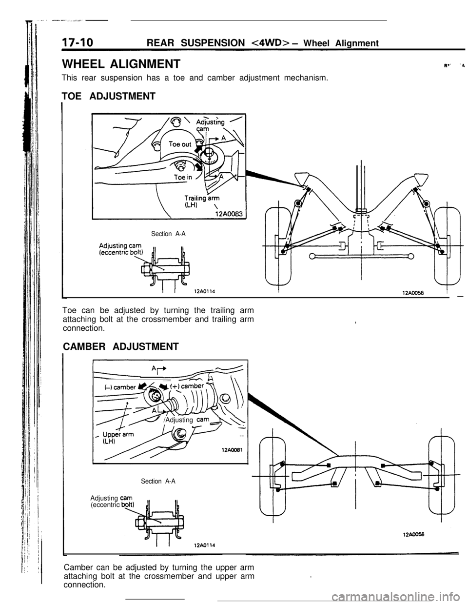
WHEEL ALIGNMENT
This rear suspension has a toe and camber adjustment mechanism.
TOE ADJUSTMENT
Section A-A
Iv’ ‘PI I
12AOllOI12AOO58I-Toe can be adjusted by turning the trailing arm
attaching bolt at the crossmember and trailing arm
connection.
,CAMBER ADJUSTMENT
I
(-1 cam&r @L Y i+) camber 7\\
__cc \
----7--w
’ --
12AcoEl
e /Adjusting cam&\\Adjusting
(eccentric
Section A-ACamber can be adjusted by turning the upper arm
attaching bolt at the crossmember and upper arm
connection..
Page 204 of 391
. -.-REAR SUSPENSION
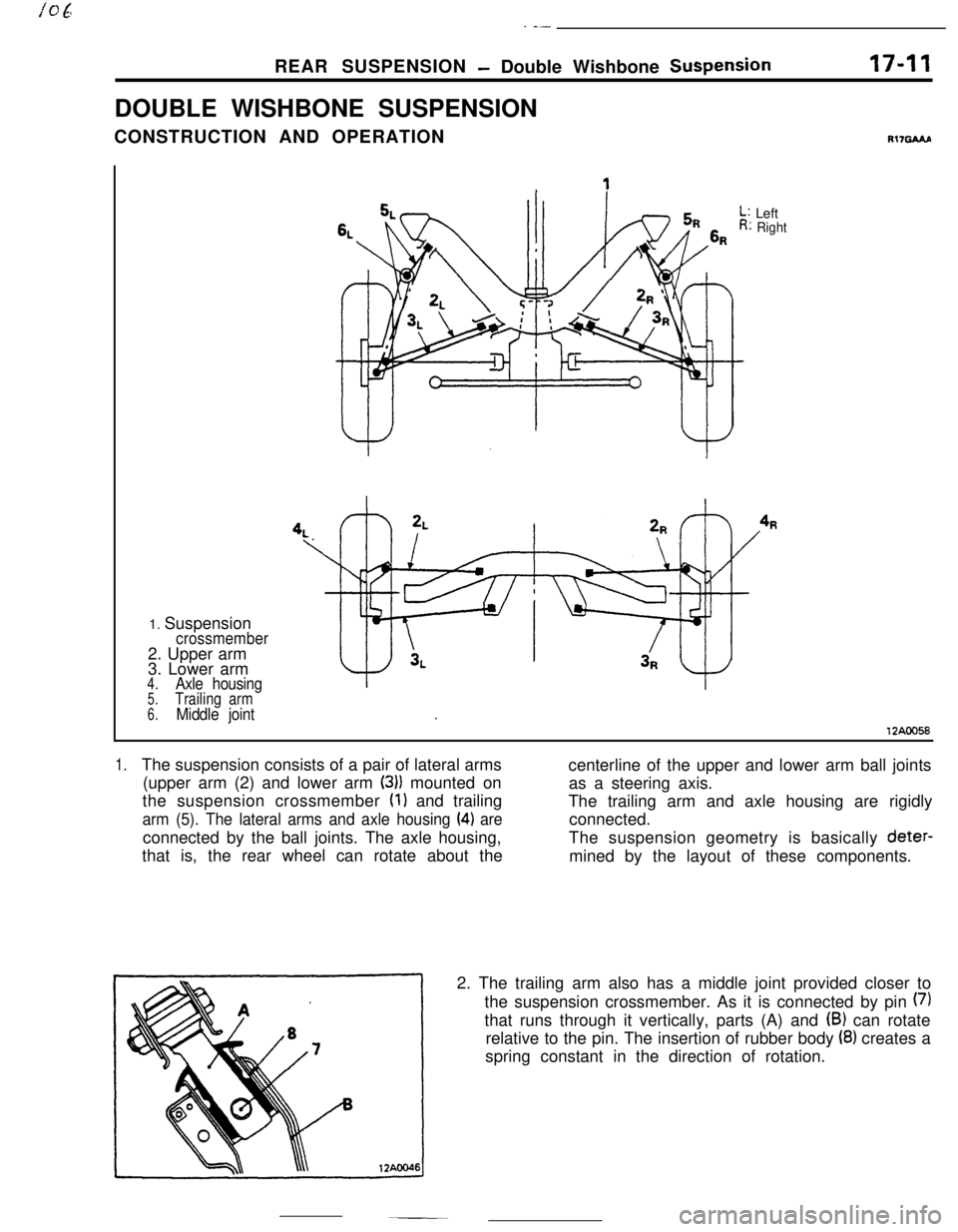
- Double Wishbone SuspensionDOUBLE WISHBONE SUSPENSION
CONSTRUCTION AND OPERATION17-11
R17GAAP1. Suspension
crossmember2. Upper arm
3. Lower arm
4.Axle housing5.Trailing arm
6.Middle jointLeft
Right
12AOO58
1.The suspension consists of a pair of lateral arms
centerline of the upper and lower arm ball joints
(upper arm (2) and lower arm
(3)) mounted on
as a steering axis.
the suspension crossmember
(1) and trailing
The trailing arm and axle housing are rigidly
arm (5). The lateral arms and axle housing (4) areconnected.
connected by the ball joints. The axle housing,The suspension geometry is basically deter-
that is, the rear wheel can rotate about the
mined by the layout of these components.
2. The trailing arm also has a middle joint provided closer to
the suspension crossmember. As it is connected by pin
(7)that runs through it vertically, parts (A) and
(B) can rotate
relative to the pin. The insertion of rubber body
(8) creates a
spring constant in the direction of rotation.
Page 205 of 391
17-12REAR SUSPENSION - Double Wishbone Suspension
12AWY
lZAOOS!
When cornering. I.to the right
I Toe-inToe angle
ReboundBump-
PositiveCamber(to body)
- Camber to ground: 0
Bump
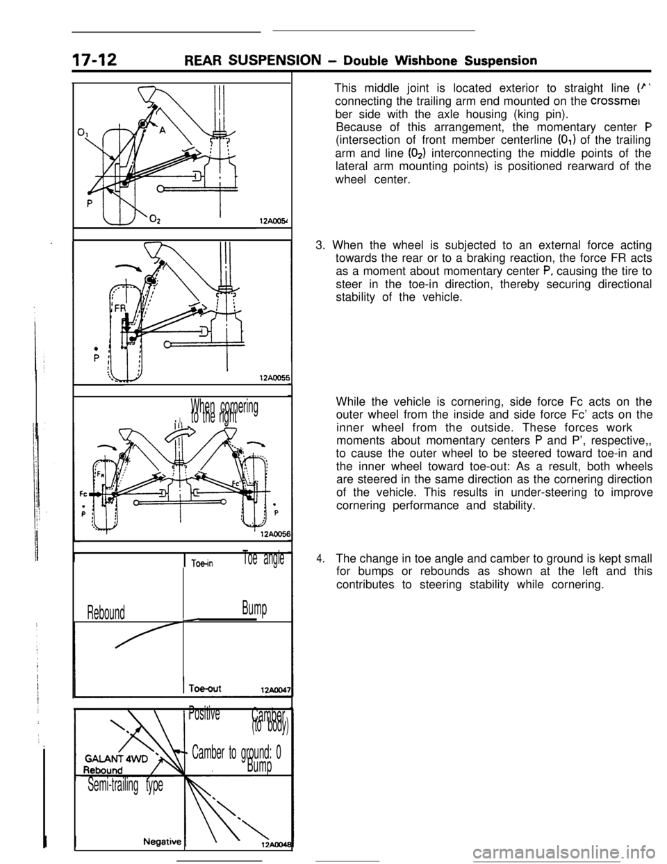
Semi-trailing typeThis middle joint is located exterior to straight line
(p’connecting the trailing arm end mounted on the crossmet
ber side with the axle housing (king pin).
Because of this arrangement, the momentary center
P(intersection of front member centerline
(0,) of the trailing
arm and line
(02) interconnecting the middle points of the
lateral arm mounting points) is positioned rearward of the
wheel center.
3. When the wheel is subjected to an external force acting
towards the rear or to a braking reaction, the force FR acts
as a moment about momentary center
P, causing the tire to
steer in the toe-in direction, thereby securing directional
stability of the vehicle.
While the vehicle is cornering, side force Fc acts on the
outer wheel from the inside and side force Fc’ acts on the
inner wheel from the outside. These forces work
moments about momentary centers
P and P’, respective,,
to cause the outer wheel to be steered toward toe-in and
the inner wheel toward toe-out: As a result, both wheels
are steered in the same direction as the cornering direction
of the vehicle. This results in under-steering to improve
cornering performance and stability.
4.The change in toe angle and camber to ground is kept small
for bumps or rebounds as shown at the left and this
contributes to steering stability while cornering.
Page 206 of 391
-
REAR SUSPENSION -Double Wishbone Suspension17-13
Member supponbushingI
12AOO5
Upper arm
Link diagram of ordinarydouble wishbone suspension system
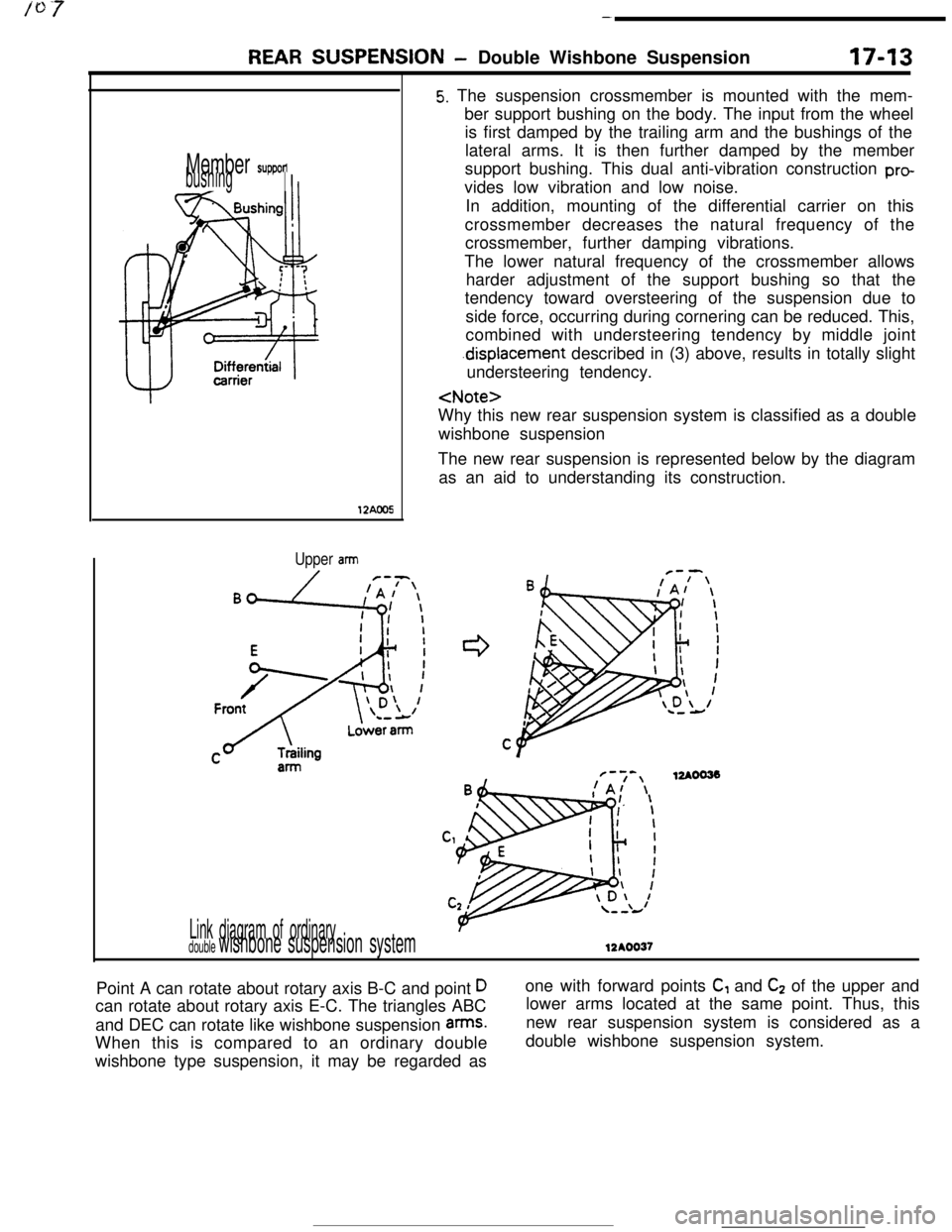
5. The suspension crossmember is mounted with the mem-
ber support bushing on the body. The input from the wheel
is first damped by the trailing arm and the bushings of the
lateral arms. It is then further damped by the member
support bushing. This dual anti-vibration construction
provides low vibration and low noise.
In addition, mounting of the differential carrier on this
crossmember decreases the natural frequency of the
crossmember, further damping vibrations.
The lower natural frequency of the crossmember allows
harder adjustment of the support bushing so that the
tendency toward oversteering of the suspension due to
side force, occurring during cornering can be reduced. This,
combined with understeering tendency by middle joint
.displacement described in (3) above, results in totally slight
understeering tendency.
wishbone suspension
The new rear suspension is represented below by the diagram
as an aid to understanding its construction.
F-7-,12AOO33!A/ \
12AOO37Point A can rotate about rotary axis B-C and point
Dcan rotate about rotary axis E-C. The triangles ABC
and DEC can rotate like wishbone suspension
arms.When this is compared to an ordinary double
wishbone type suspension, it may be regarded asone with forward points
C, and C2 of the upper and
lower arms located at the same point. Thus, this
new rear suspension system is considered as a
double wishbone suspension system.
Page 207 of 391
17-14REAR SUSPENSION - Double Wishbone Suwension
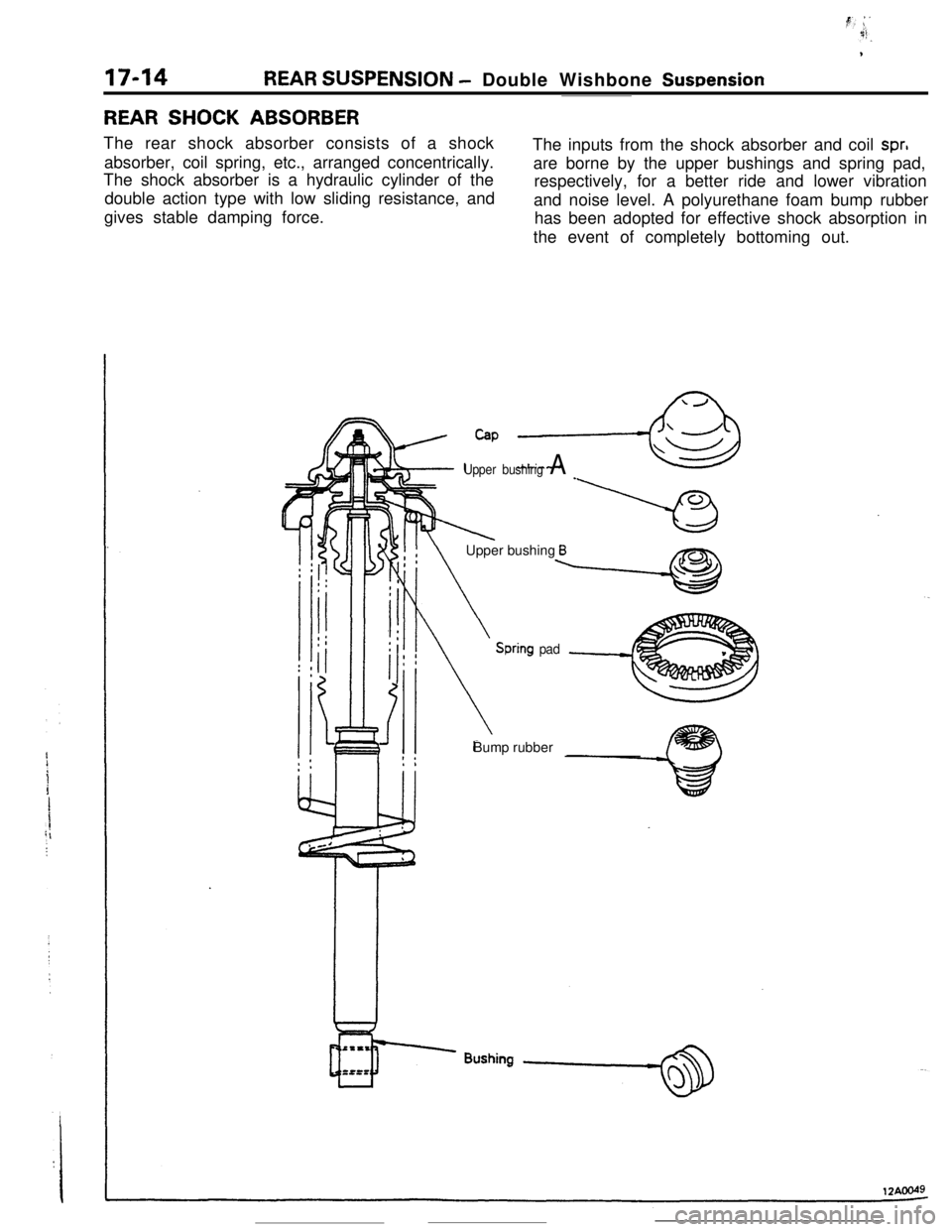
REAR SHOCK ABSORBERThe rear shock absorber consists of a shock
absorber, coil spring, etc., arranged concentrically.
The shock absorber is a hydraulic cylinder of the
double action type with low sliding resistance, and
gives stable damping force.The inputs from the shock absorber and coil
spr,are borne by the upper bushings and spring pad,
respectively, for a better ride and lower vibration
and noise level. A polyurethane foam bump rubber
has been adopted for effective shock absorption in
the event of completely bottoming out.
Cap ,-&
Upper bushing A _
IlXk!! \Upper bushing Bx?nb
Spring padBump rubber
Page 208 of 391
REAR SUSPENSION- Double Wishbone Suspension17-15TRAILING ARM
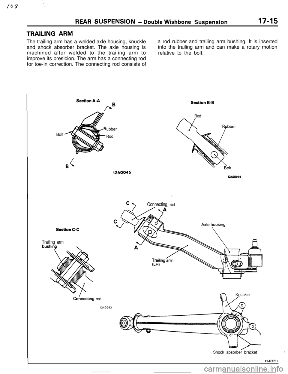
The trailing arm has a welded axle housing, knuckle
and shock absorber bracket. The axle housing is
machined after welded to the trailing arm to
improve its presicion. The arm has a connecting rod
for toe-in correction. The connecting rod consists ofa rod rubber and trailing arm bushing. It is inserted
into the trailing arm and can make a rotary motion
relative to the bolt.
Section A-A
bBBolt
ubber
RodRod12A0045
Ii
Connecting rod
Section C-C
Trailing armbushiyg
\Co;lnecting
rod1240043
Section B-B
Knuckleii-l /
Shock absorber bracket,,
I12ACO51
Page 209 of 391
1
1746REAR SUSPENSION - Double Wishbone Suspension
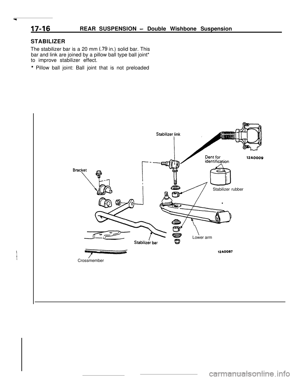
STABILIZER
The stabilizer bar is a 20 mm
I.79 in.) solid bar. This
bar and link are joined by a pillow ball type ball joint*
to improve stabilizer effect.
* Pillow ball joint: Ball joint that is not preloaded
12A0009
!!IStabilizer rubberStabiliz&
barCrossmemberz
\Lower arm
12A0087
Page 210 of 391
19-I
POWER
_
GENERAL INFORMATION
.._ . . . . .
OIL PUMP ........................................................10POWER STEERING GEAR BOX