MITSUBISHI ECLIPSE 1990 Service Manual
Manufacturer: MITSUBISHI, Model Year: 1990, Model line: ECLIPSE, Model: MITSUBISHI ECLIPSE 1990Pages: 391, PDF Size: 15.27 MB
Page 211 of 391
19-2 POWER STEERING
Rlh
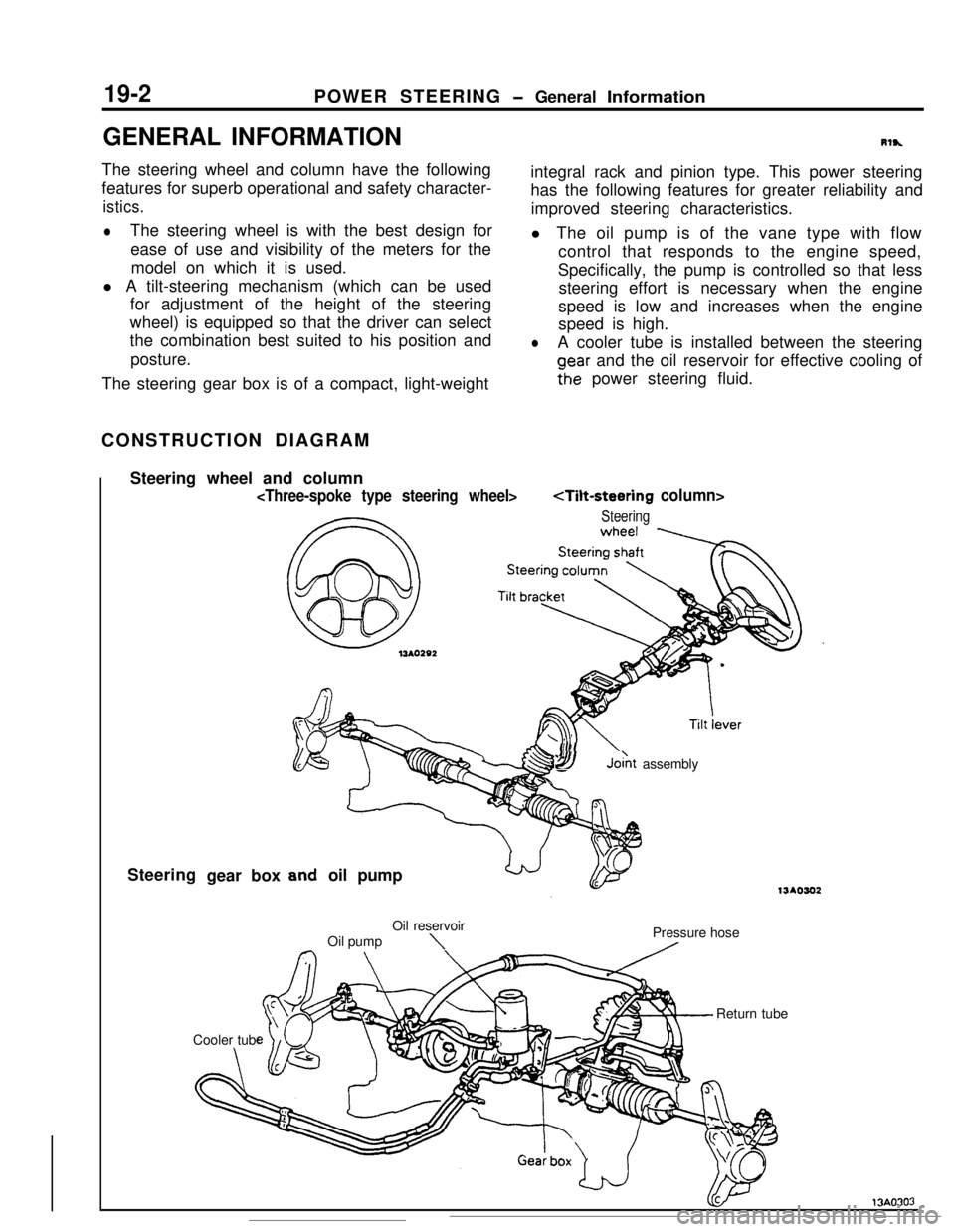
integral rack and pinion type. This power steering
oear and the oil reservoir for effective cooling of
Fhe power steering fluid.The steering gear box is of a compact, light-weight
Steering
SYJo& assembly
oil pump
\Pressure hose
A
Page 212 of 391
POWER STEERING- General Information19-3
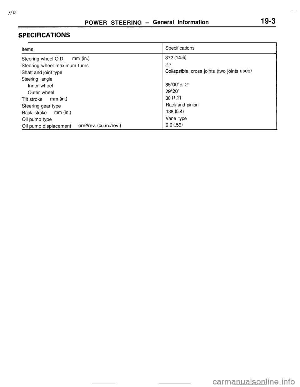
SPEClFlCATlONSItems
Steering wheel O.D.
mm (in.)Steering wheel maximum turns
Shaft and joint type
Steering angleInner wheel
Outer wheel
Tilt strokemm
(in.1Steering gear type
Rack strokemm (in.)Oil pump type
Oil pump displacement
cm3/rev. (cu.in./rev.)Specifications
372
(14.6)
2.7
Collapsible, cross joints (two joints used)
35”OO’ + 2”
29”20’
30
(1.2)
Rack and pinion
138
(5.41
Vane type9.6
l.59)
Page 213 of 391
19-4POWER STEERING - Tilt Steering Construction
TILT STEERING CONSTRUCTIONRlW
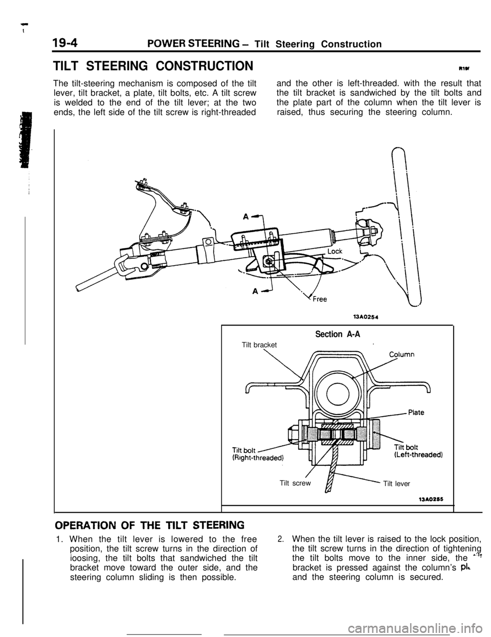
The tilt-steering mechanism is composed of the tilt
lever, tilt bracket, a plate, tilt bolts, etc. A tilt screw
is welded to the end of the tilt lever; at the two
ends, the left side of the tilt screw is right-threadedand the other is left-threaded. with the result that
the tilt bracket is sandwiched by the tilt bolts and
the plate part of the column when the tilt lever is
raised, thus securing the steering column.
13A0254Tilt bracket
Section A-A.
’Tilt screwfi Tilt lever13AO256
OPERATION OF THE TILT STEERING1. When the tilt lever is lowered to the free
position, the tilt screw turns in the direction of
ioosing, the tilt bolts that sandwiched the tilt
bracket move toward the outer side, and the
steering column sliding is then possible.
2.When the tilt lever is raised to the lock position,
the tilt screw turns in the direction of tightening
the tilt bolts move to the inner side, the
*“?bracket is pressed against the column’s
pi&and the steering column is secured.
Page 214 of 391

.-. --POWER STEERING
- Power Steering Gear Box Construction19-5
-POWER STEERING GEAR BOX CONSTRUCTIONRlsJLIIUB,
ne steering gear box is of the rack and pinion type
with a built-in hydraulic control unit which uses a
compact and highly reliable rotary valve.The steering gear box, in the same way as the
manual steering gear box, is installed to the body by
way of the mounting rubber in order to reduce the
transmission of vibrations.
Section A-A
Beari
1-$ysy input shaft
To oilreservoir
LFrom oil
I’Rotary valve
Yoke spring
13A0257
Section B-B
From oil pumpTo oil reservoir
To cylinder tubeleft chamber
To cylinder tube
13A0077right chamber
Page 215 of 391
19-6POWER STEERING- Pinion and Valve Assembly Construction
PINION AND VALVE ASSEMBLY
CONSTRUCTION
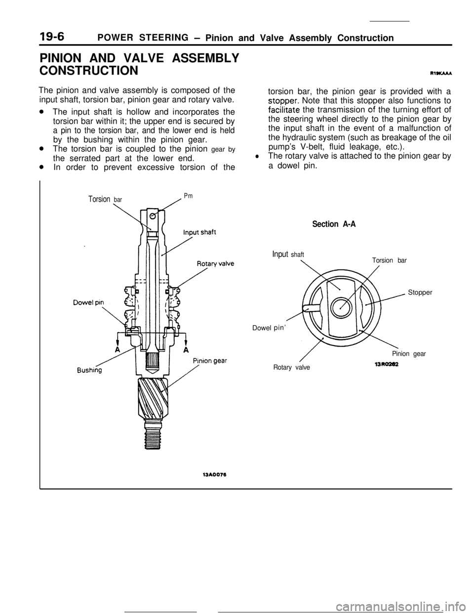
RISKAMThe pinion and valve assembly is composed of the
input shaft, torsion bar, pinion gear and rotary valve.torsion bar, the pinion gear is provided with a
stopper. Note that this stopper also functions to
The input shaft is hollow and incorporates the
fa&tate the transmission 6i the turning effort of
torsion bar within it; the upper end is secured bythe steering wheel directly to the pinion gear by
a pin to the torsion bar, and the lower end is heldthe input shaft in the event of a malfunction of
by the bushing within the pinion gear.the hydraulic system (such as breakage of the oil
The torsion bar is coupled to the pinion gear bypump’s V-belt, fluid leakage, etc.).
the serrated part at the lower end.
lThe rotary valve is attached to the pinion gear by
In order to prevent excessive torsion of thea dowel pin.
Torsion barPm13AOO76Dowel
Section A-A
Input shaft\Torsion barpin’Stopper
/Rotary valvePinion gear1310202
Page 216 of 391
:POWER STEERING
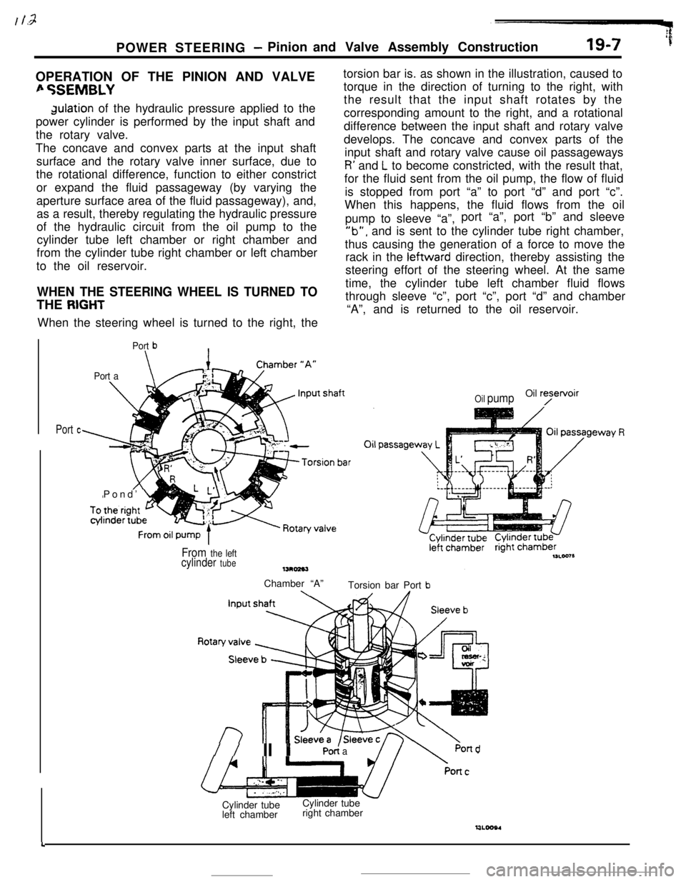
- Pinion and Valve Assembly Construction19-7 ’fOPERATION OF THE PINION AND VALVE
fi %EMBLYdulation of the hydraulic pressure applied to the
power cylinder is performed by the input shaft and
the rotary valve.
The concave and convex parts at the input shaft
surface and the rotary valve inner surface, due to
the rotational difference, function to either constrict
or expand the fluid passageway (by varying the
aperture surface area of the fluid passageway), and,
as a result, thereby regulating the hydraulic pressure
of the hydraulic circuit from the oil pump to the
cylinder tube left chamber or right chamber and
from the cylinder tube right chamber or left chamber
to the oil reservoir.
WHEN THE STEERING WHEEL IS TURNED TOTHE
RIGHTWhen the steering wheel is turned to the right, the
Port b\
Port a\Pond’
Ltorsion bar is. as shown in the illustration, caused to
torque in the direction of turning to the right, with
the result that the input shaft rotates by the
corresponding amount to the right, and a rotational
difference between the input shaft and rotary valve
develops. The concave and convex parts of the
input shaft and rotary valve cause oil passageways
R’ and L to become constricted, with the result that,
for the fluid sent from the oil pump, the flow of fluid
is stopped from port “a” to port “d” and port “c”.
When this happens, the fluid flows from the oil
pump to sleeve “a”,port “a”, port “b” and sleeve
‘lb”, and is sent to the cylinder tube right chamber,
thus causing the generation of a force to move the
rack in the leftward direction, thereby assisting the
steering effort of the steering wheel. At the same
time, the cylinder tube left chamber fluid flows
through sleeve “c”, port “c”, port “d” and chamber
“A”, and is returned to the oil reservoir.
Port c
Oil pumpOil ryetvoir
From the leftcylinder tubeChamber “A”
Torsion bar Port
b
//II YPO< aPond
4Cylinder tube
left chamberCylinder tube
right chamber
Page 217 of 391
19-8POWER STEERING -Pinion and Valve Assembly Construction
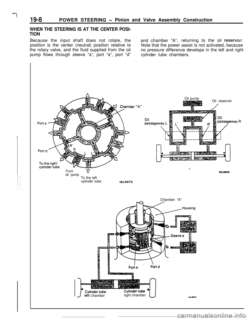
WHEN THE STEERING IS AT THE CENTER POSI-
TIONBecause the input shaft does not rotate, the
and chamber “A”,returning to the oil reservoir.
position is the center (neutral) position relative to
Note that the power assist is not activated, because
the rotary valve, and the fluid supplied from the oil
no pressure difference develops in the left and right
pump flows through sleeve “a”, port “a”, port “d”
cylinder tube chambers.
Fromoil pumpVTo the left
cylinder tubeOil pump
Oil reservoir
/
13L0072Chamber “A”
JI& chamberright chamber
Page 218 of 391
POWER STEERING -Pinion and Valve Assembly Construction
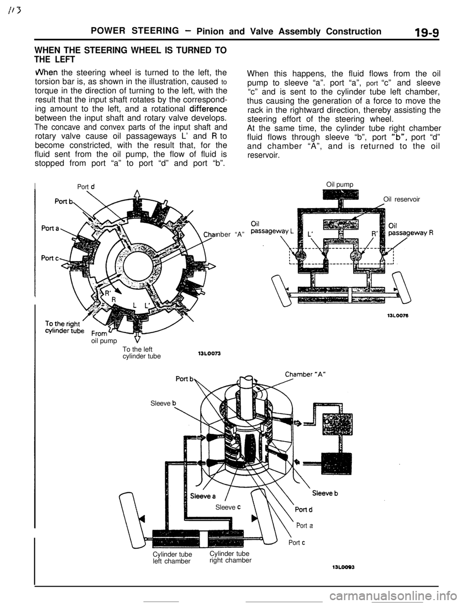
WHEN THE STEERING WHEEL IS TURNED TO
THE LEFT
IS-9
JVhen the steering wheel is turned to the left, the
torsion bar is, as shown in the illustration, caused to
torque in the direction of turning to the left, with the
result that the input shaft rotates by the correspond-
ing amount to the left, and a rotational
diff.erencebetween the input shaft and rotary valve develops.
The concave and convex parts of the input shaft androtary valve cause oil passageways L’ and
R to
become constricted, with the result that, for the
fluid sent from the oil pump, the flow of fluid is
stopped from port “a” to port “d” and port “b”.
IPort dnber “A”
SleeveWhen this happens, the fluid flows from the oil
pump to sleeve “a”. port “a”, port “c” and sleeve
“c” and is sent to the cylinder tube left chamber,
thus causing the generation of a force to move the
rack in the rightward direction, thereby assisting the
steering effort of the steering wheel.
At the same time, the cylinder tube right chamber
fluid flows through sleeve “b”, port
“b”, port “d”
and chamber “A”, and is returned to the oil
reservoir.Oil pump
Oil reservoir
Cylinder tube
left chamberCylinder tube
right chamber
\
Port a
Port cSleeve
coil pump
VTo the left
cylinder tube
13L0073
Page 219 of 391
POWER STEERING - Oil Pump13A0067
Insi
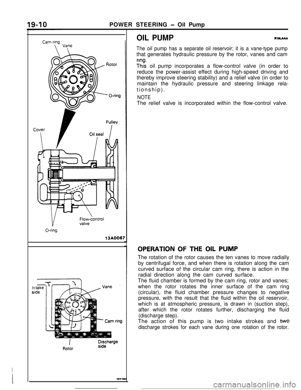
OIL PUMPRlUAM
The oil pump has a separate oil reservoir; it is a vane-type pumpthat generates hydraulic pressure by the rotor, vanes and cam
y”ht oil pump incorporates a flow-control valve (in order to
reduce the power-assist effect during high-speed driving and
thereby improve steering stability) and a relief valve (in order to
maintain the hydraulic pressure and steering linkage rela-
tionship).
NOTEThe relief valve is incorporated within the flow-control valve.
OPERATION OF THE OIL PUMP
The rotation of the rotor causes the ten vanes to move radially
by centrifugal force, and when there is rotation along the cam
curved surface of the circular cam ring, there is action in the
radial direction along the cam curved surface.
The fluid chamber is formed by the cam ring, rotor and vanes;
when the rotor rotates the inner surface of the cam ring
(circular), the fluid chamber pressure changes to negative
pressure, with the result that the fluid within the oil reservoir,
which is at atmospheric pressure, is drawn in (suction step),
after which the rotor rotates further, discharging the fluid
(discharge step).
The action of this pump is two intake strokes and
two
discharge strokes for each vane during one rotation of the rotor.
Page 220 of 391
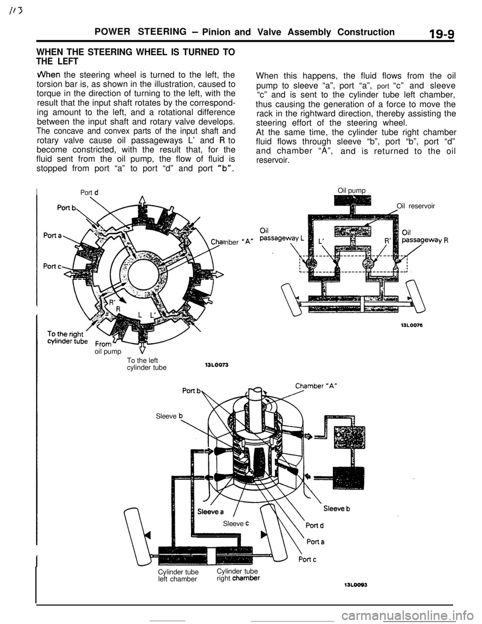
POWER STEERING- Pinion and Valve Assembly Construction19-9
WHEN THE STEERING WHEEL IS TURNED TO
THE LEFT
JVhen the steering wheel is turned to the left, the
torsion bar is, as shown in the illustration, caused to
torque in the direction of turning to the left, with the
result that the input shaft rotates by the correspond-
ing amount to the left, and a rotational difference
between the input shaft and rotary valve develops.
The concave and convex parts of the input shaft androtary valve cause oil passageways L’ and
R to
become constricted, with the result that, for the
fluid sent from the oil pump, the flow of fluid is
stopped from port “a” to port “d” and port
“b”.
IPort dnber
*oil pump
VTo the left
cylinder tube13LOO73
SleeveWhen this happens, the fluid flows from the oil
pump to sleeve “a”,port “a”, port “c” and sleeve
“c” and is sent to the cylinder tube left chamber,
thus causing the generation of a force to move the
rack in the rightward direction, thereby assisting the
steering effort of the steering wheel.
At the same time, the cylinder tube right chamber
fluid flows through sleeve “b”, port “b”, port “d”
and chamber “A”,
and is returned to the oil
reservoir.Oil pump
Oil reservoir
Sleeve
cCylinder tube
left chamberCylinder tube
right chamber
‘Y R