MITSUBISHI ECLIPSE 1990 Service Manual
Manufacturer: MITSUBISHI, Model Year: 1990, Model line: ECLIPSE, Model: MITSUBISHI ECLIPSE 1990Pages: 391, PDF Size: 15.27 MB
Page 161 of 391
FUEL SYSTEM -Idle Speed Control14-49
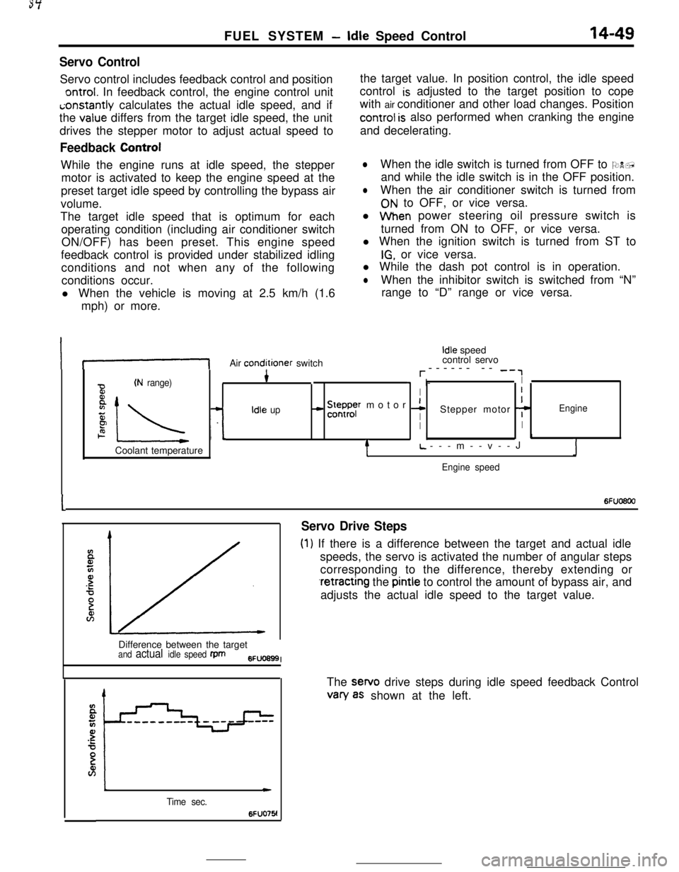
Servo ControlServo control includes feedback control and position
ontrol. In feedback control, the engine control uniti;onstantly calculates the actual idle speed, and if
the
value differs from the target idle speed, the unit
drives the stepper motor to adjust actual speed to
Feedback ControlWhile the engine runs at idle speed, the stepper
motor is activated to keep the engine speed at the
preset target idle speed by controlling the bypass air
volume.
The target idle speed that is optimum for each
operating condition (including air conditioner switch
ON/OFF) has been preset. This engine speed
feedback control is provided under stabilized idling
conditions and not when any of the following
conditions occur.
l When the vehicle is moving at 2.5 km/h (1.6
mph) or more.the target value. In position control, the idle speed
control
is adjusted to the target position to cope
with air conditioner and other load changes. Position
control is also performed when cranking the engine
and decelerating.
lWhen the idle switch is turned from OFF to ON,
and while the idle switch is in the OFF position.
lWhen the air conditioner switch is turned from
ON to OFF, or vice versa.
l When power steering oil pressure switch is
turned from ON to OFF, or vice versa.
l When the ignition switch is turned from ST to
IG, or vice versa.
l While the dash pot control is in operation.
lWhen the inhibitor switch is switched from “N”
range to “D” range or vice versa.
If-1Air conditioner switch
Idle speed
control servo
r------ -- -‘,
(N range)4* I-I
BI
8
IL -L
- !5ysr motor 1I
zIdle upIStepper motor 7Engine
PII2. I.1Coolant temperature
tL.---m--v--JJ
Engine speed
I6Fuo6oo
Servo Drive Steps
(1) If there is a difference between the target and actual idle
speeds, the servo is activated the number of angular steps
corresponding to the difference, thereby extending or
.retracting the pintle to control the amount of bypass air, and
adjusts the actual idle speed to the target value.
Difference between the target
and actual idle speed fpm6FUO699I
Time sec.
c
6FUO76!The sewo drive steps during idle speed feedback Control
van/ as shown at the left.
Page 162 of 391
14-50FUEL SYSTEM- Idle Speed Control
SDeed adiustina screwI -Throttle valve
Lw-3O(-22) 0132) 30(86! 601140) 9ofl94)Coolant temperature
“C (OF)6FUO641
E94
72--2--I
Q--.-.-z
3201.000 --4-\-\
5P9.o%IIIaI L-2O(-41 Of3214Of104)801176)Coolant temperature
“C VF)6FU028E
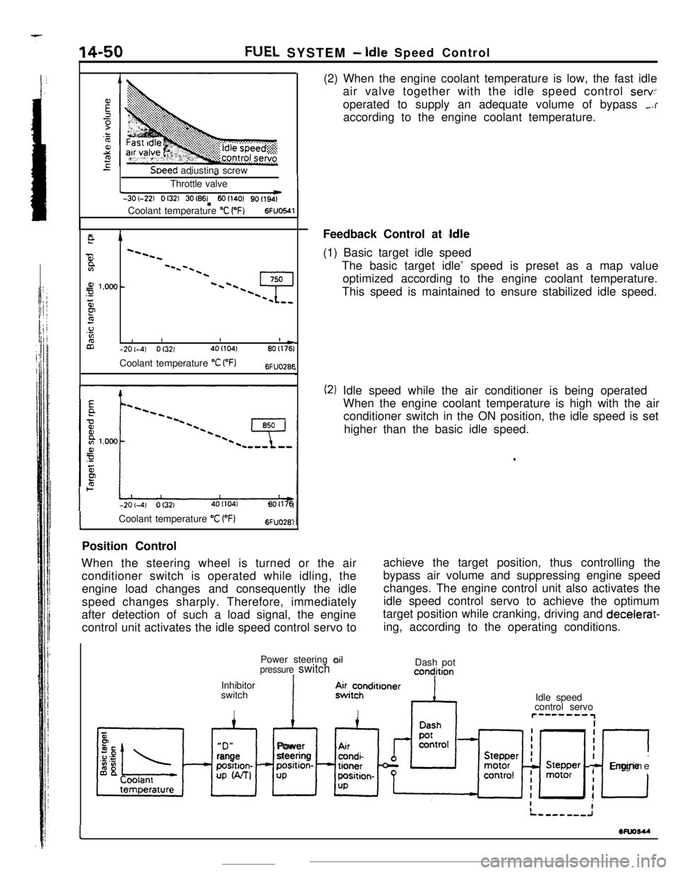
-201-4) Of3214OI104180(176(2) When the engine coolant temperature is low, the fast idle
air valve together with the idle speed control
servoperated to supply an adequate volume of bypass
,.raccording to the engine coolant temperature.
Feedback Control at
Idle(1) Basic target idle speed
The basic target idle’ speed is preset as a map value
optimized according to the engine coolant temperature.
This speed is maintained to ensure stabilized idle speed.
(2) Idle speed while the air conditioner is being operated
When the engine coolant temperature is high with the air
conditioner switch in the ON position, the idle speed is set
higher than the basic idle speed.
,
ICoolant temperature “C VF)6FUO28:Position Control
When the steering wheel is turned or the air
conditioner switch is operated while idling, theachieve the target position, thus controlling the
engine load changes and consequently the idlebypass air volume and suppressing engine speed
changes. The engine control unit also activates the
speed changes sharply. Therefore, immediately
after detection of such a load signal, the engine
control unit activates the idle speed control servo toidle speed control servo to achieve the optimum
target position while cranking, driving and decelerat-
ing, according to the operating conditions.
Power steering oil
pressure switchIInhibitor
switch
IDash pot
concjition“D”
xl
rangeposition-
UP W-U
IAlPower
steeringposition-
UP.4~i~hnditioner
IIdle speed
control servor”--““IiiI
I
c
IEngine
I
I
1wuosu
-
Page 163 of 391
FUEL SYSTEM -Idle Speed Control14-51
_ 0 (32)80 (175)Coolant temperature “C (“F)6FUO2653
ATarget position during operation
of the power steering systemIDLE CONTROL SERVO POSITION CONTROL WHEN THE
ENGINE IS IDLING
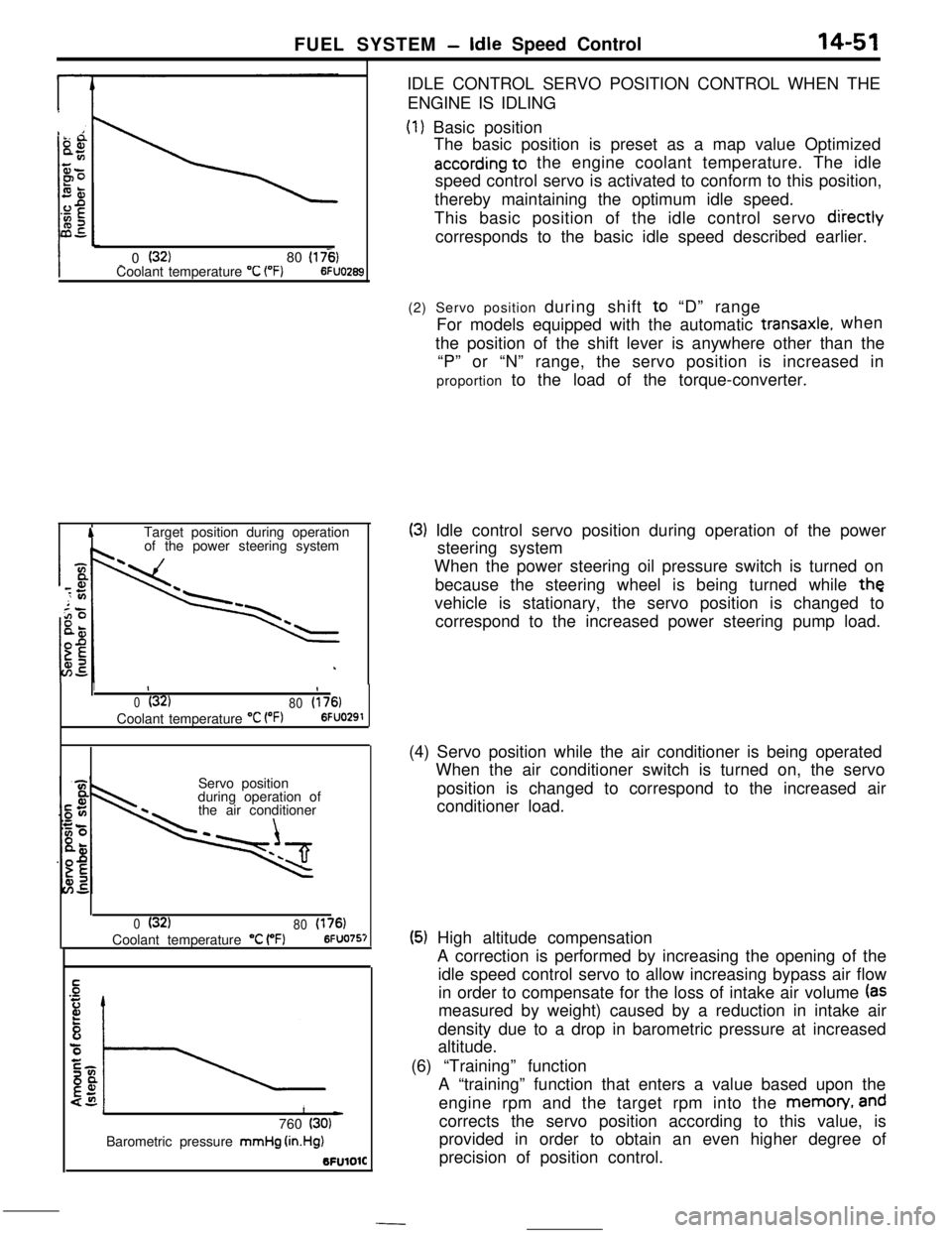
(1) Basic position
The basic position is preset as a map value Optimized
according to the engine coolant temperature. The idle
speed control servo is activated to conform to this position,
thereby maintaining the optimum idle speed.
This basic position of the idle control servo
diiectlycorresponds to the basic idle speed described earlier.
1II
0(32)
80(176)Coolant temperature
“C VW6FUO291Servo position
during operation of
the air conditioner
0(32)
80(176)Coolant temperature “C (“F)6FUO757
1L)760 (30)Barometric pressure mmHg
(in.Hg)BFUlOlC(2) Servo position during shift to “D” range
For models equipped with the automatic
transaxle.when
the position of the shift lever is anywhere other than the
“P” or “N” range, the servo position is increased in
proportion to the load of the torque-converter.
(3) Idle control servo position during operation of the power
steering system
When the power steering oil pressure switch is turned on
because the steering wheel is being turned while
thevehicle is stationary, the servo position is changed to
correspond to the increased power steering pump load.
(4) Servo position while the air conditioner is being operated
When the air conditioner switch is turned on, the servo
position is changed to correspond to the increased air
conditioner load.
(5) High altitude compensation
A correction is performed by increasing the opening of the
idle speed control servo to allow increasing bypass air flow
in order to compensate for the loss of intake air volume
(asmeasured by weight) caused by a reduction in intake air
density due to a drop in barometric pressure at increased
altitude.
(6) “Training” function
A “training” function that enters a value based upon the
engine rpm and the target rpm into the memon/,
andcorrects the servo position according to this value, is
provided in order to obtain an even higher degree of
precision of position control.
Page 164 of 391
--
14-52FUEL SYSTEM - Idle Speed Control
4
Start of deceleration
DLhq ON
position
I*2 to 6
Time sec.6FUO295
II)
0(32180(176)Temperature “C 1°F)6FUO29t
CONTROL WHEN THE ENGINE SPEED IS UNUSUALLY LOWThe followi
gcontrols are provided when the engine speecfalls below
i5;D rpm after the engine has been fully warmed-up
[with engine coolant temperature more than
55°C (131”F)].
(1) During feedback control
The idle speed control servo is activated immediately by a
particular number of angular steps which represent the
feedback correction.
(2) During servo position control
The idle speed control servo is activated to conform to
aposition corresponding to an increased number of steps
(46
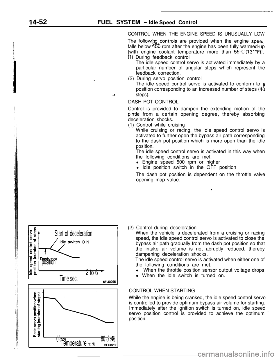
steps).DASH POT CONTROL
Control is provided to dampen the extending motion of the
pintle from a certain opening degree, thereby absorbing
deceleration shocks.
(1) Control while cruising
While cruising or racing, the idle speed control servo is
activated to further open the bypass air path corresponding
to the dash pot position which is more open than the idle
position.The idle speed control servo is activated in this way when
the following conditions are met.
l Engine speed 500 rpm or higher
l Idle position switch in the OFF position
The dash pot position is dependent on the throttle valve
opening map value.,
(2) Control during deceleration
When the vehicle is decelerated from a cruising or racing
speed, the idle speed control servo is activated to close the
bypass air path gradually from the dash pot position so that
the intake air volume is not abruptly reduced, thereby
dampening deceleration shocks.
The idle speed control servo is activated when either one of
the following conditions are met.
lWhen the throttle position sensor output voltage drops
l When the idle switch is turned on.
CONTROL WHEN STARTING
While the engine is being cranked, the idle speed control servo
is controlled to provide optimum bypass air volume for starting.
Immediately after the ignition switch is turned on, idle speed
servo position control is provided to achieve the optimum
_
position.
Page 165 of 391
FUEL SYSTEM -Idle Speed Control I Power Supply Control14-53
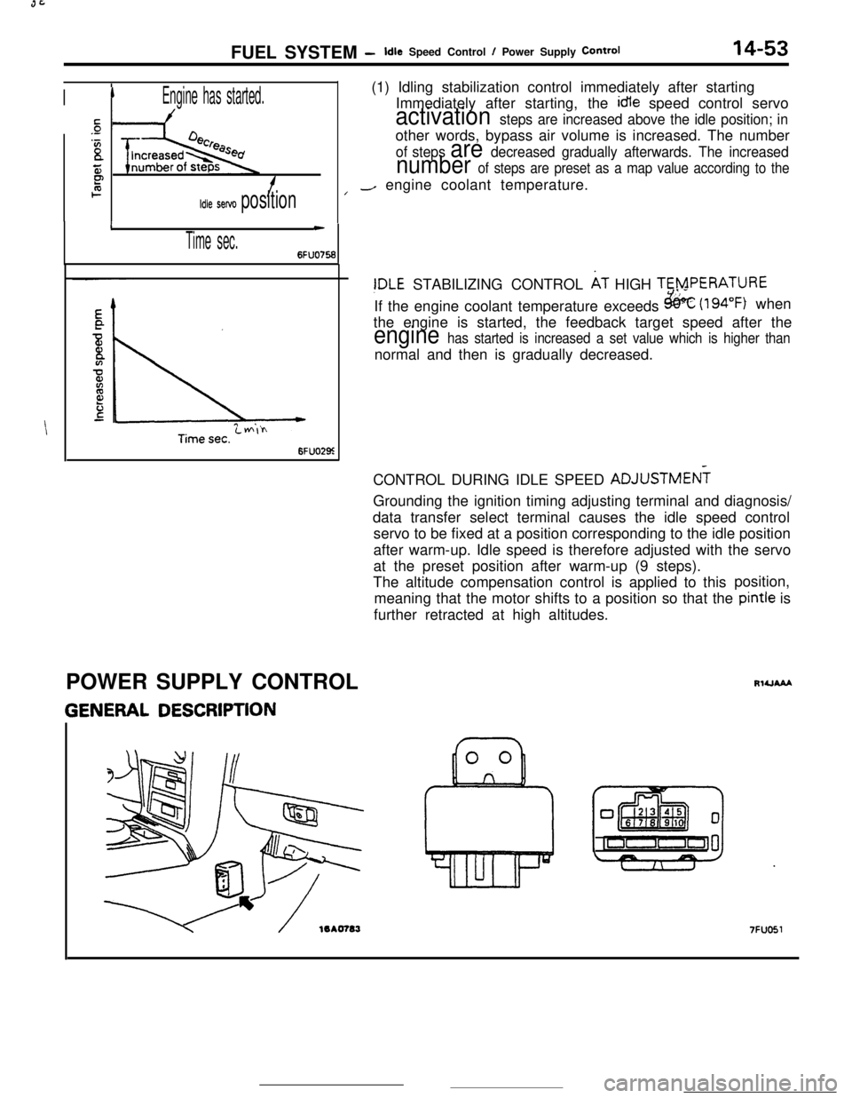
IIEngine has started.(1) Idling stabilization control immediately after starting
Immediately after starting, the idle speed control servo
sactivation steps are increased above the idle position; in.-
‘Bother words, bypass air volume is increased. The numberof steps are decreased gradually afterwards. The increased
55number of steps are preset as a map value according to theP2f/-/ engine coolant temperature.
Idle servo position
I
Time sec.
c
6FUO756
6FUO29z
!DLE STABILIZING CONTROL AT HIGH TERPERATURE
If the engine coolant temperature exceeds
&k (194°F) when
the engine is started, the feedback target speed after the
engine has started is increased a set value which is higher thannormal and then is gradually decreased.
CONTROL DURING IDLE SPEED ADJUSTMEN?
Grounding the ignition timing adjusting terminal and diagnosis/
data transfer select terminal causes the idle speed control
servo to be fixed at a position corresponding to the idle position
after warm-up. Idle speed is therefore adjusted with the servo
at the preset position after warm-up (9 steps).
The altitude compensation control is applied to thisposition,
meaning that the motor shifts to a position so that the pintle is
further retracted at high altitudes.
POWER SUPPLY CONTROL
GENERAL DESCRIPTION
RlUAAA
7FUO51
Page 166 of 391
FUEL SYSTEM- Power Supply Control
Battery
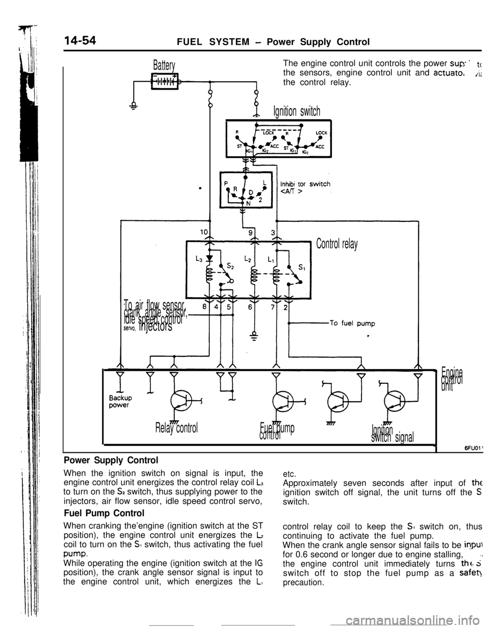
L11The engine control unit controls the power
suv ’tcthe sensors, engine control unit and
actuate,A;the control relay.
-P
.
-p.Ignition switch
Inn yr
To air flow sensor,crank angle sensor,idle speed controlsetvo. injectors
Control relay
Relay controlFuel pump
controlIgnitionswitch signal
Enginecontrol
unit
I6FUOl’
Power Supply ControlWhen the ignition switch on signal is input, the
engine control unit energizes the control relay coil
L3to turn on the
S2 switch, thus supplying power to the
injectors, air flow sensor, idle speed control servo,
Fuel Pump ControlWhen cranking the’engine (ignition switch at the ST
position), the engine control unit energizes the
Lcoil to turn on the
S switch, thus activating the fuel
pump.While operating the engine (ignition switch at the
IGposition), the crank angle sensor signal is input to
the engine control unit, which energizes the
L,
etc.Approximately seven seconds after input of
theignition switch off signal, the unit turns off the
Sswitch.
control relay coil to keep the
SI switch on, thus
continuing to activate the fuel pump.
When the crank angle sensor signal fails to be
inputfor 0.6 second or longer due to engine stalling,
.,the engine control unit immediately turns
thz. 5switch off to stop the fuel pump as a safet)
precaution.
Page 167 of 391
FUEL SYSTEM -Air Conditioner Relay Control14-55AIR CONDITIONER RELAY CONTROL
Batterylgnltlon
switch
Air conditionerswitch
@OFF ON
Coolanttemperature
switch
RlUCAAA
/Air condittoner
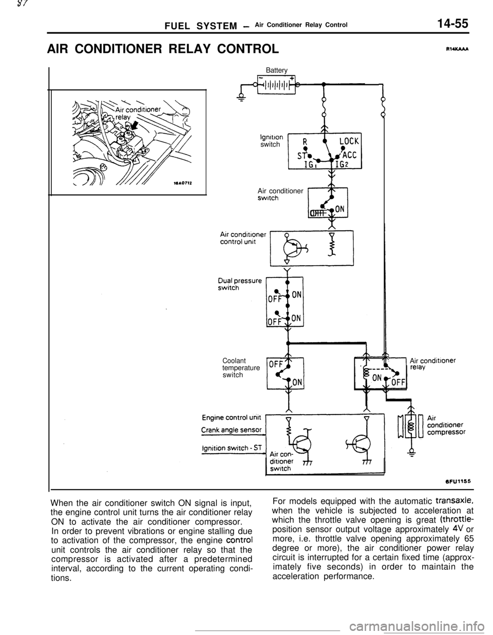
When the air conditioner switch ON signal is input,
the engine control unit turns the air conditioner relay
ON to activate the air conditioner compressor.
In order to prevent vibrations or engine stalling due
to activation of the compressor, the engine control
unit controls the air conditioner relay so that the
compressor is activated after a predetermined
interval, according to the current operating condi-
tions.For models equipped with the automatic
transaxle,when the vehicle is subjected to acceleration at
which the throttle valve opening is great (throttle-
position sensor output voltage approximately
4V or
more, i.e. throttle valve opening approximately 65
degree or more), the air conditioner power relay
circuit is interrupted for a certain fixed time (approx-
imately five seconds) in order to maintain the
acceleration performance.
Page 168 of 391
14-56FUEL SYSTEM -Supercharge Pressure Control
SUPERCHARGEPRESSURE CONTROL
sensor
lEngine control
unit
Knockcontrol
ControlrelayIntercooler
h&l --/I- h
.. .Waste gate
P solenoid valve
Air cleaner,
Power
transistorWaste gate
unit
actuatorOf
CT1 +p$?V~~~t
6FUO665
II\Spring set pressure
Turbo pressure acting5Fuo570
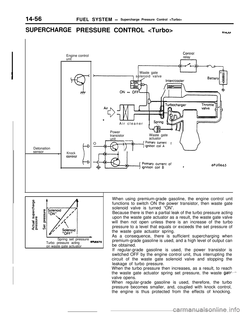
on waste gate actuatorWhen using premium-grade gasoline, the engine control unit
functions to switch ON the power transistor, then waste gate
solenoid valve is turned “ON”.
Because there is then a partial leak of the turbo pressure acting
upon the waste gate actuator as a result, the waste gate valve
will then not open unless there is an increase of the turbo
pressure to a level that equals or exceeds the set pressure of
the waste gate actuator spring.
As a consequence, there is sufficient supercharging when
premium-grade gasoline is used, and a high level of output can
be obtained.
If regular-grade gasoline is used, the power transistor is
switched OFF by the engine control unit, thus interrupting the
circuit of the waste gate solenoid valve and stopping the
leakage of turbo pressure.
When the turbo pressure then increases, as a result, to reach
the waste gate actuator spring set pressure, the waste
gate----valve opens.
When regular-grade gasoline is used, therefore, the turbo
pressure becomes smaller, and, coupled with knock control,
the engine is thus protected from the effects of knocking.
Page 169 of 391
FUEL SYSTEMAir Flow Sensor (AFSI Filter Reset Control
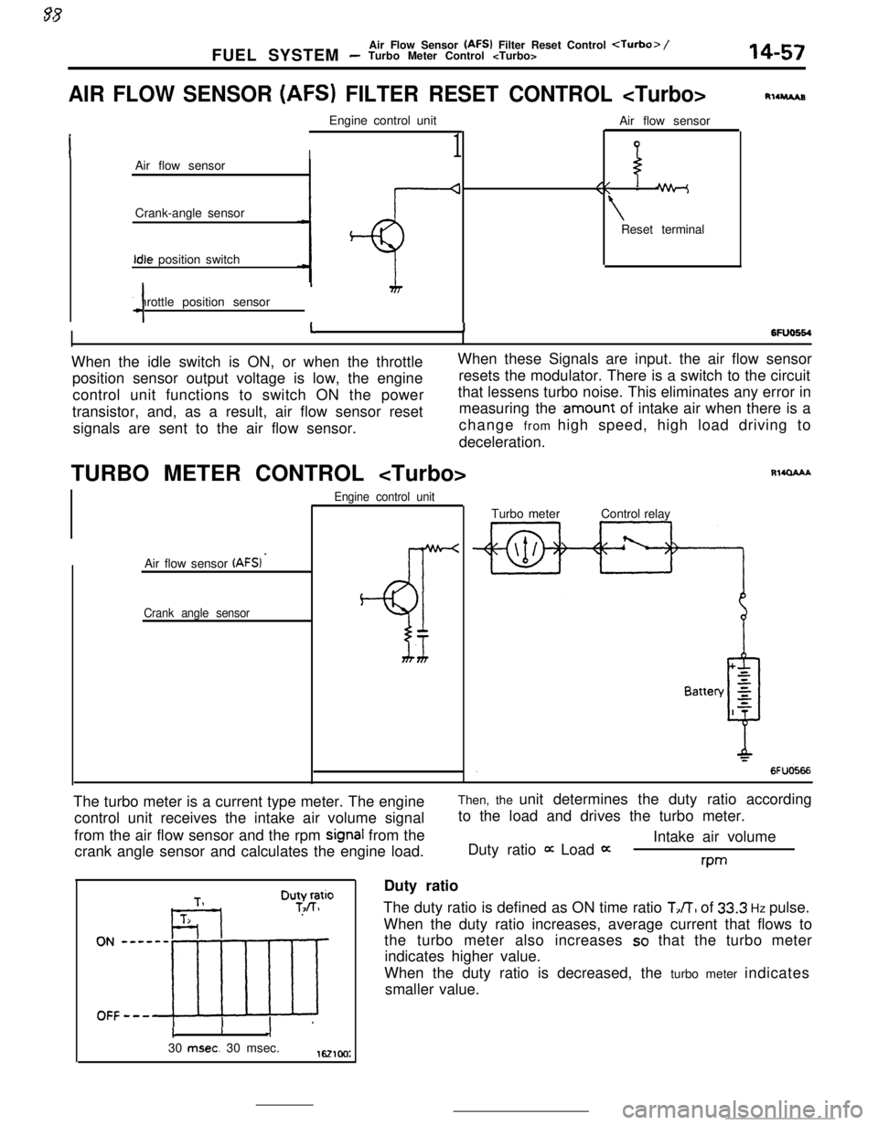
AIR FLOW SENSOR (AFS) FILTER RESET CONTROL
I1Air flow sensor
Crank-angle sensorIdle position switch
Throttle position sensor
4Air flow sensor
//\\ -
\Reset terminal
RllruAs
6FlJo664I11When the idle switch is ON, or when the throttleWhen these Signals are input. the air flow sensor
position sensor output voltage is low, the engineresets the modulator. There is a switch to the circuit
control unit functions to switch ON the powerthat lessens turbo noise. This eliminates any error in
transistor, and, as a result, air flow sensor resetmeasuring the
.amount of intake air when there is a
signals are sent to the air flow sensor.change from high speed, high load driving to
deceleration.
TURBO METER CONTROL
Air flow sensor
(AFSI ’
Crank angle sensorEngine control unit
BT
Rl4QAAATurbo meterControl relay
The turbo meter is a current type meter. The engine
control unit receives the intake air volume signal
from the air flow sensor and the rpm
signal from the
crank angle sensor and calculates the engine load.Then, the unit determines the duty ratio according
to the load and drives the turbo meter.
Intake air volume
Duty ratio
it Load 0:rwDuty ratio
The duty ratio is defined as ON time ratio
TJT, of 33.3 Hz pulse.
When the duty ratio increases, average current that flows to
the turbo meter also increases
so that the turbo meter
indicates higher value.
When the duty ratio is decreased, the turbo meter indicates
smaller value.
cI30
msec. 30 msec.1621cm:
Page 170 of 391
._ ..-
14-58
.-FUEL SYSTEM
- Accelerator Components
-7
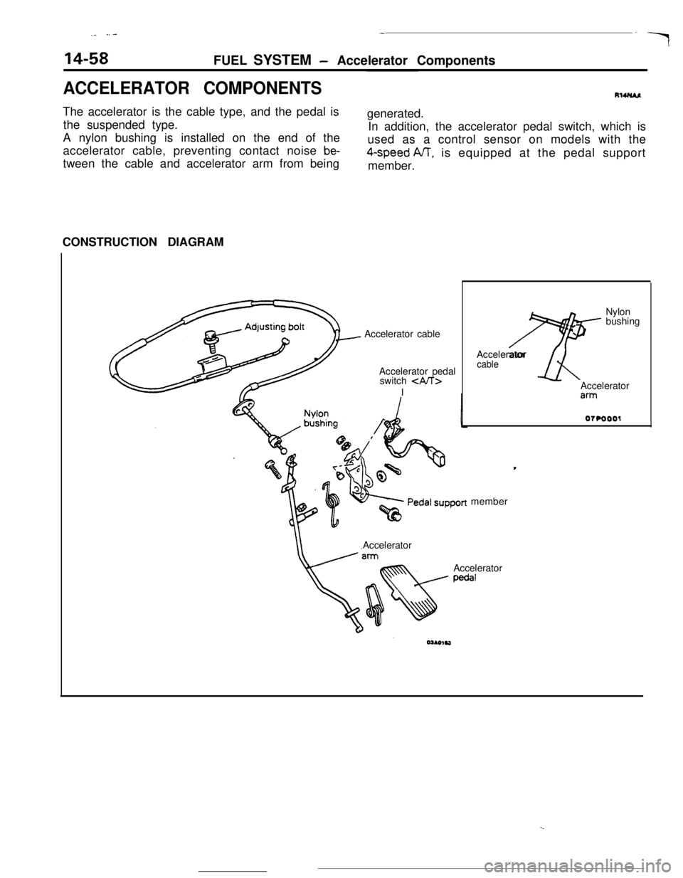
ACCELERATOR COMPONENTSRlUUAAThe accelerator is the cable type, and the pedal is
the suspended type.
A nylon bushing is installed on the end of the
accelerator cable, preventing contact noise
be-tween the cable and accelerator arm from beinggenerated.
In addition, the accelerator pedal switch, which is
used as a control sensor on models with the4-speed NT, is equipped at the pedal support
member.
CONSTRUCTION DIAGRAM
Accelerator cable
Accelerator pedal
switch
\Accelerator
cableAccelerator
ahmember
Accelerator
Accelerator
pedal