MITSUBISHI ECLIPSE 1990 Service Manual
Manufacturer: MITSUBISHI, Model Year: 1990, Model line: ECLIPSE, Model: MITSUBISHI ECLIPSE 1990Pages: 391, PDF Size: 15.27 MB
Page 221 of 391
POWER STEERING - Oil Pump
OIL PUMP13A0067
Insi
m-
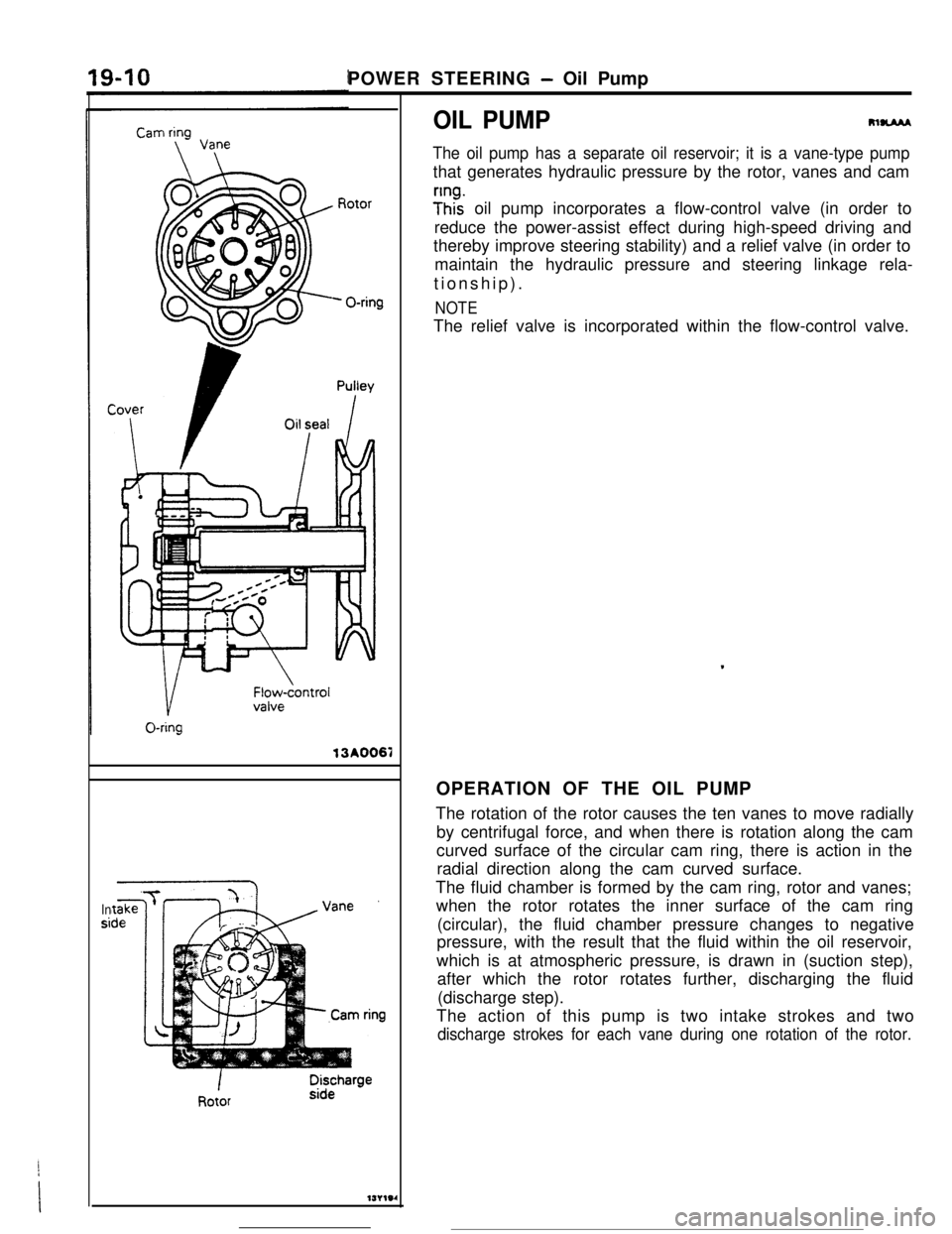
The oil pump has a separate oil reservoir; it is a vane-type pumpthat generates hydraulic pressure by the rotor, vanes and cam
;Inhz oil pump incorporates a flow-control valve (in order to
reduce the power-assist effect during high-speed driving and
thereby improve steering stability) and a relief valve (in order to
maintain the hydraulic pressure and steering linkage rela-
tionship).
NOTEThe relief valve is incorporated within the flow-control valve.
.OPERATION OF THE OIL PUMP
The rotation of the rotor causes the ten vanes to move radially
by centrifugal force, and when there is rotation along the cam
curved surface of the circular cam ring, there is action in the
radial direction along the cam curved surface.
The fluid chamber is formed by the cam ring, rotor and vanes;
when the rotor rotates the inner surface of the cam ring
(circular), the fluid chamber pressure changes to negative
pressure, with the result that the fluid within the oil reservoir,
which is at atmospheric pressure, is drawn in (suction step),
after which the rotor rotates further, discharging the fluid
(discharge step).
The action of this pump is two intake strokes and two
discharge strokes for each vane during one rotation of the rotor.
Page 222 of 391
POWER STEERING - Oil Pump
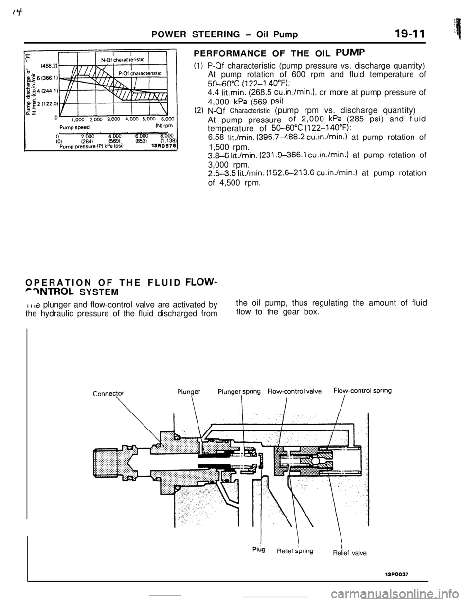
PERFORMANCE OF THE OIL PUMP
(1)
19-11 i
P-Qf characteristic (pump pressure vs. discharge quantity)
At pump rotation of 600 rpm and fluid temperature of
50-6O”C (122-l 40°F):4.4
litmin. (268.5 cu.in./min.), or more at pump pressure of
4,000
kPa (569 psi)
N-Qf Characteristic (pump rpm vs. discharge quantity)
At pump pressureof 2,000
kPa (285 psi) and fluid
temperature of
50-60X (122-140°F):
6.58
lit./min. (396.7-488.2 cu.in./min.) at pump rotation of
1,500 rpm.
3.8-6 lit./min. (231.9-366.1 cu.in./min.) at pump rotation of
3,000 rpm.
2.5-3.5 Mnin. (152.6-213.6 cu.in./min.) at pump rotation
of 4,500 rpm.
OPERATION OF THE FLUID
FLOW-
r7NTROL SYSTEM
I t 13 plunger and flow-control valve are activated bythe oil pump, thus regulating the amount of fluid
the hydraulic pressure of the fluid discharged fromflow to the gear box.
Pl;lgRelief ipring\
Relief valve13POO37
Page 223 of 391
19-12POWER STEERING - Oil Pump
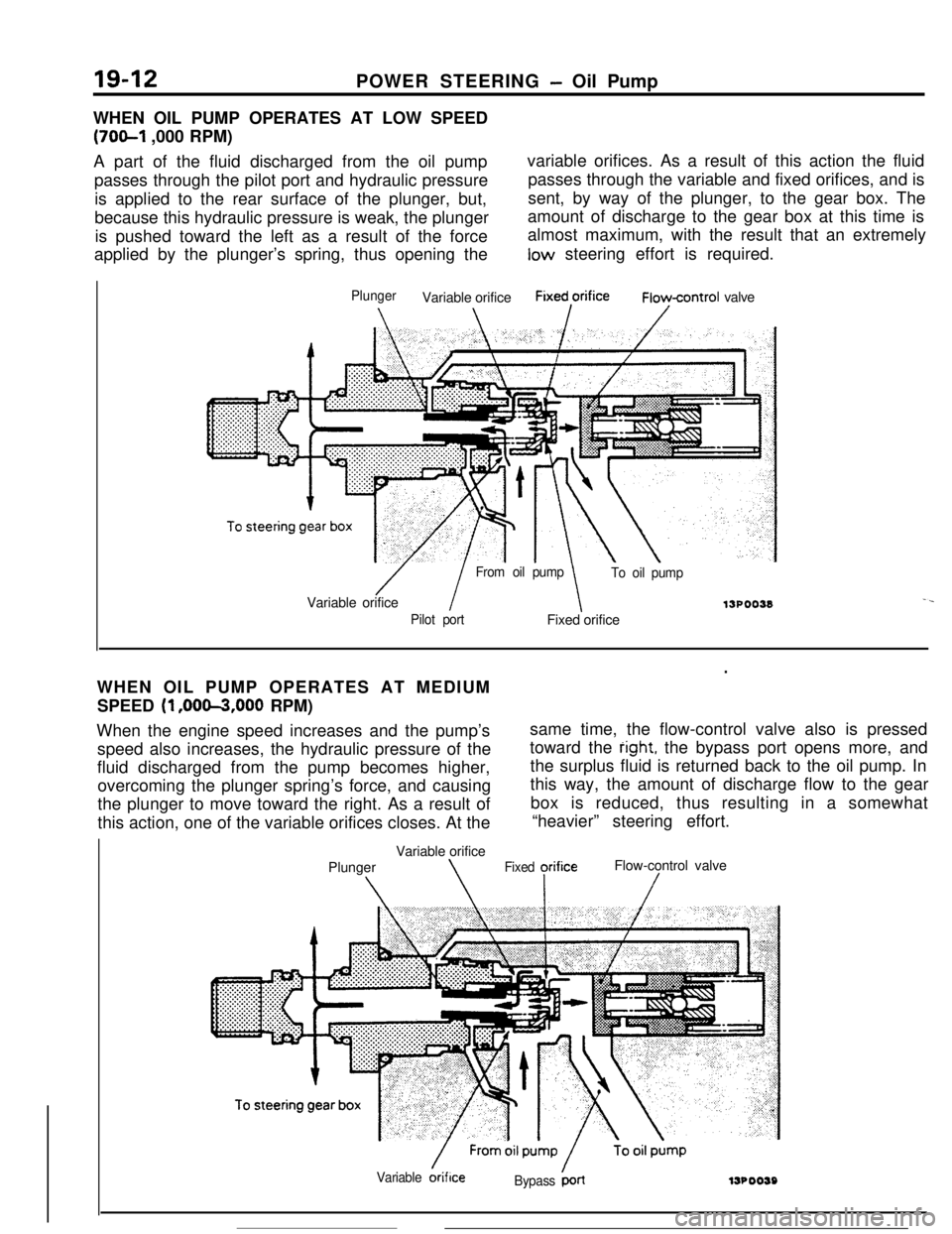
WHEN OIL PUMP OPERATES AT LOW SPEED
(70&l ,000 RPM)
A part of the fluid discharged from the oil pumpvariable orifices. As a result of this action the fluid
passes through the pilot port and hydraulic pressurepasses through the variable and fixed orifices, and is
is applied to the rear surface of the plunger, but,sent, by way of the plunger, to the gear box. The
because this hydraulic pressure is weak, the plungeramount of discharge to the gear box at this time is
is pushed toward the left as a result of the forcealmost maximum, with the result that an extremely
applied by the plunger’s spring, thus opening thelow steering effort is required.
PlungerVariable orificeFixed,orificeFioycontrol valve
/ I
From oil pump
To oil pumpVariable orifice
13POO38-.
Pilot portFixed orifice
.WHEN OIL PUMP OPERATES AT MEDIUM
SPEED
(1 ,OOm,OOO RPM)
When the engine speed increases and the pump’ssame time, the flow-control valve also is pressed
speed also increases, the hydraulic pressure of thetoward the
right, the bypass port opens more, and
fluid discharged from the pump becomes higher,the surplus fluid is returned back to the oil pump. In
overcoming the plunger spring’s force, and causingthis way, the amount of discharge flow to the gear
the plunger to move toward the right. As a result ofbox is reduced, thus resulting in a somewhat
this action, one of the variable orifices closes. At the“heavier” steering effort.
Variable orifice
PlungerFlow-control valve
\\Fixed yrifice/
Variable &iflceBypass ‘LrllJPOO59
Page 224 of 391
i t-7POWER STEERING
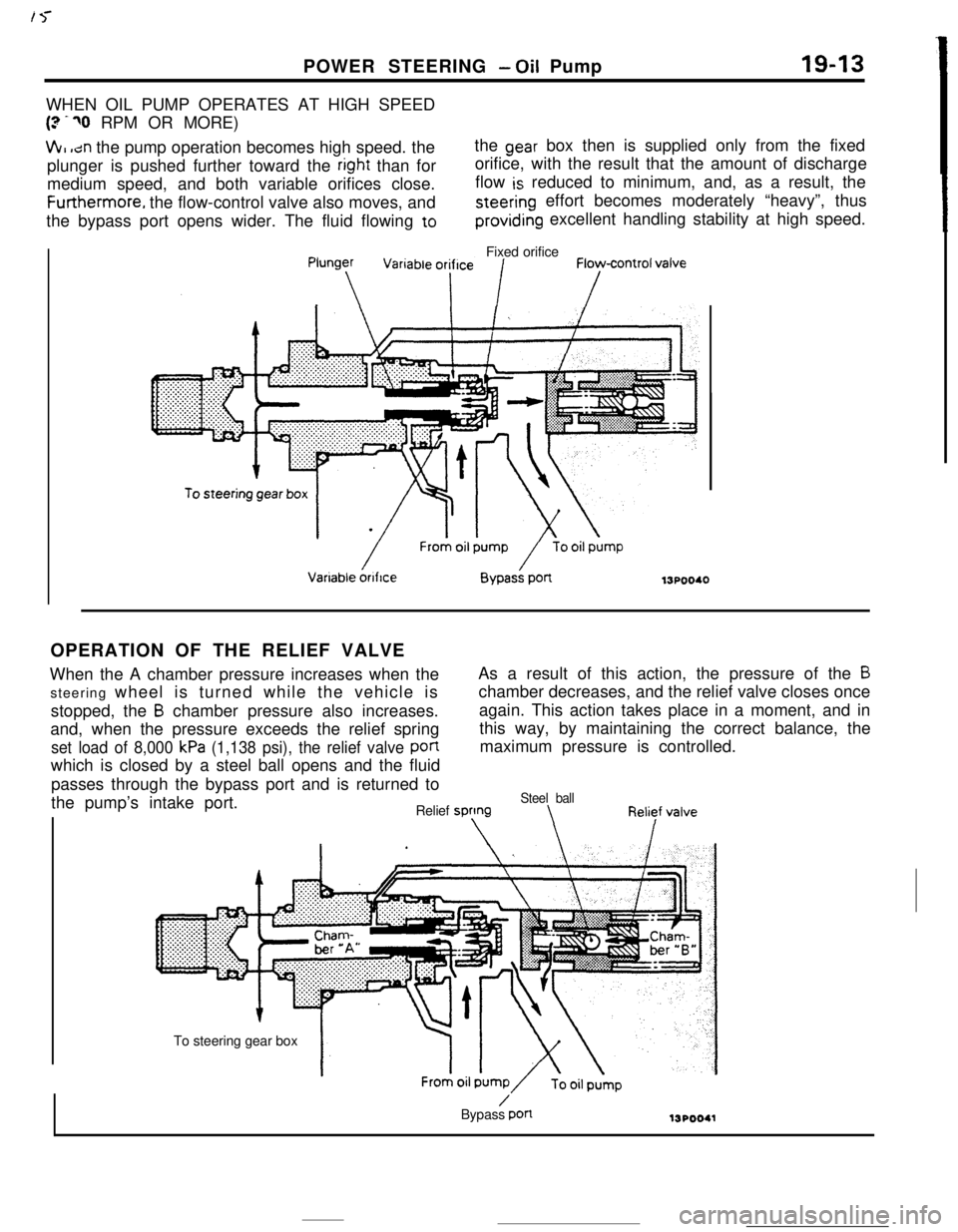
- Oil Pump19-13WHEN OIL PUMP OPERATES AT HIGH SPEED
(? -70 RPM OR MORE)
VII, ,dn the pump operation becomes high speed. thethe gear box then is supplied only from the fixed
plunger is pushed further toward the
right than fororifice, with the result that the amount of discharge
medium speed, and both variable orifices close.flow
is reduced to minimum, and, as a result, theFurthermore. the flow-control valve also moves, and
steering effort becomes moderately “heavy”, thus
the bypass port opens wider. The fluid flowing to
providing excellent handling stability at high speed.
Fixed orifice13POO40
OPERATION OF THE RELIEF VALVE
When the A chamber pressure increases when theAs a result of this action, the pressure of the
Bsteering wheel is turned while the vehicle ischamber decreases, and the relief valve closes once
stopped, the
B chamber pressure also increases.again. This action takes place in a moment, and in
and, when the pressure exceeds the relief springthis way, by maintaining the correct balance, the
set load of 8,000 kPa (1,138 psi), the relief valve panmaximum pressure is controlled.
which is closed by a steel ball opens and the fluid
passes through the bypass port and is returned to
the pump’s intake port.
Steel ballRelief sprtngTo steering gear box
/Bypass pan
WPOO41
Page 225 of 391
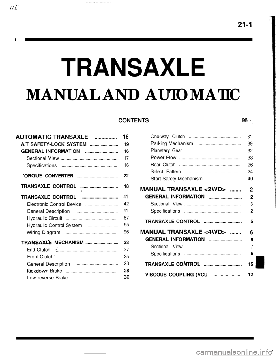
21-l
k
TRANSAXLE
‘TORQUE CONVERTE R....................................22
TRANSAXLZ MECHANIS M............................ 23
EndClutch<.................................................. 27
Front Clutch’.................................................... 25
KickdownBrake............................................ 28
Low-reverse Brake........................................30
One-way Clutch............................................ 31
CObROL................................ 15I
VISCOUS COUPLING (VCU). . . . . . . . . . . . . . . . . . . . . . . . 12
Page 226 of 391
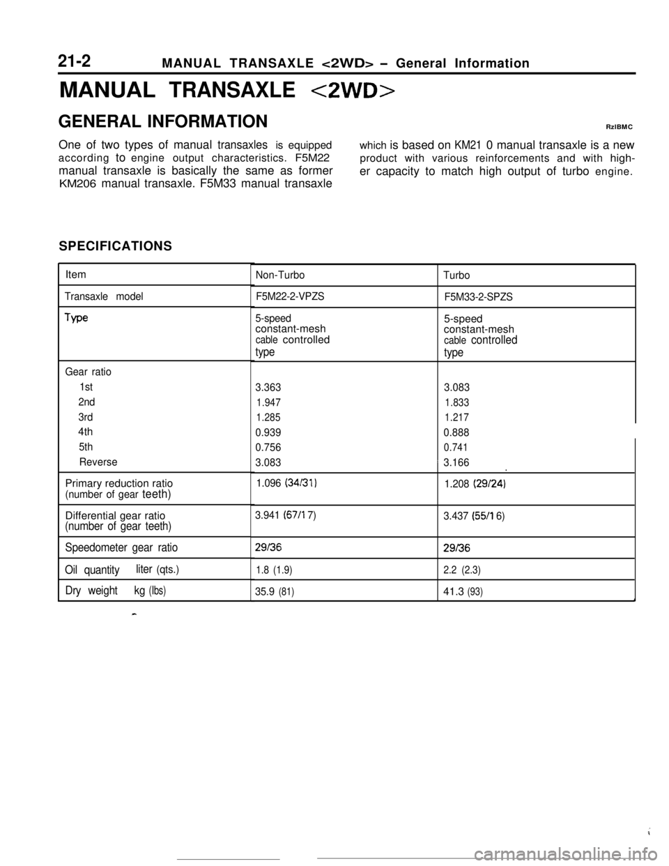
21-2 MANUAL TRANSAXLE
GENERAL INFORMATION
We
Gear ratio
(34131)
3.941 (67/l 7)
29f36
1.8 (1.9)
o 3.166.
(29f24)
3.437 (55/l 6)
29f36
2.2 (2.3)
4
Page 227 of 391
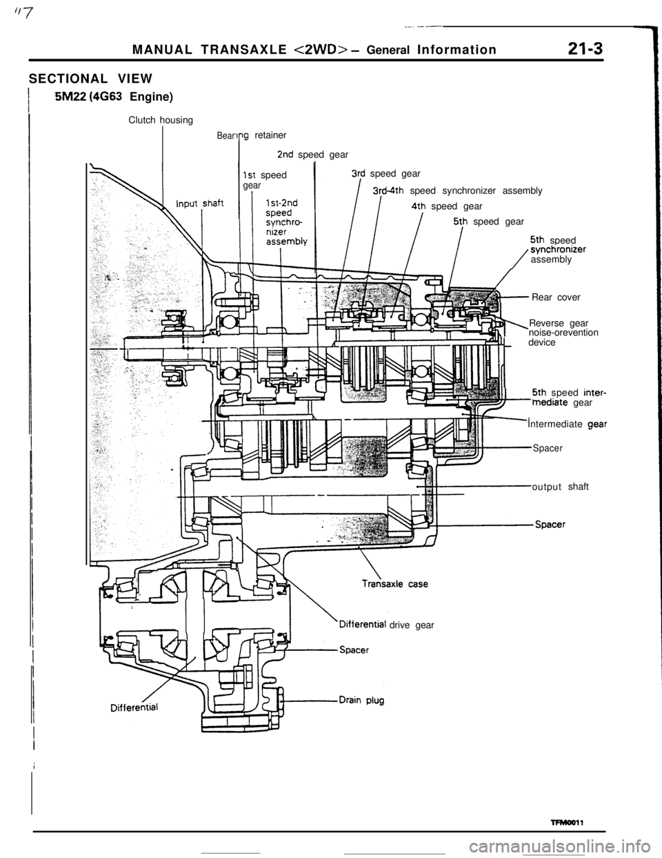
_-. ---MANUAL TRANSAXLE
<2WD> - General Information21-3SECTIONAL VIEW
:5M22 (4663 Engine)
Clutch housing
Bear‘Ing retainer
2nd speed gear
1st speedgear
3rd speed gear
3rd-4th speed synchronizer assembly4th speed gear5th speed gear5th speed
/synchronizer
assembly
ii+-Rear cover
Reverse gear
noise-orevention
tdevice5th speed inter-
inediate gear
Intermediate aear
Spaceroutputshaft
drive gear
TFMooll
Page 228 of 391
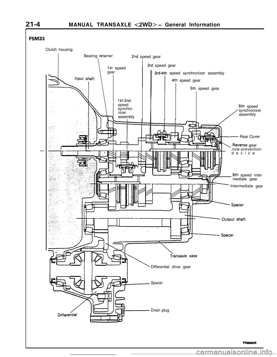
MANUAL TRANSAXLE <2WD> - General InformationF5M33
Clutch housing
Bearing retainer
\1st speedgear
2nd speed gear
I3rd speed gear
3rd-4th speed synchronizer assembly
4th speed gear
I5th speed gear
1 st-2nd
speedsynchro-
nizerassembly5th speed
synchronizer
assembly
- Rear Cover
. Reyerse gear
now-prevention
device
-5th speed inter
mediate gear
Intermediate
Differential drive gear
SpacerDrain plug
gear
Page 229 of 391
MANUAL TRANSAXLE <2WD> - Transaxle Control
21-5
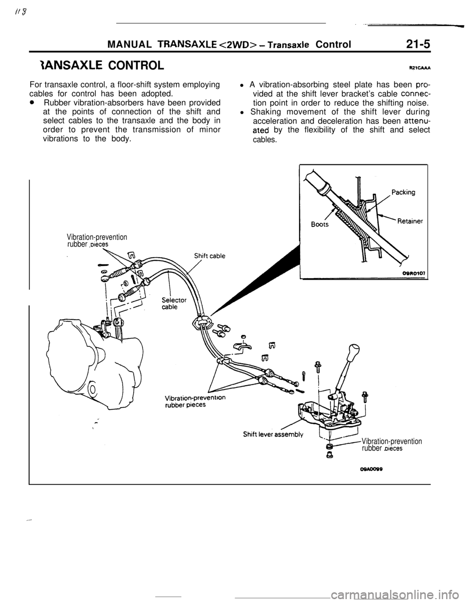
IANSAXLE CONTROLFor transaxle control, a floor-shift system employing
cables for control has been adopted.
0Rubber vibration-absorbers have been provided
at the points of connection of the shift and
select cables to the transaxle and the body in
order to prevent the transmission of minor
vibrations to the body.l A vibration-absorbing steel plate has been
pro-vided at the shift lever bracket’s cable connec-
tion point in order to reduce the shifting noise.
l Shaking movement of the shift lever during
acceleration and deceleration has been attenu-
ated by the flexibility of the shift and select
cables.
Vibration-preventionrubber Dieces
Vibration-preventionrubber Dieces
Page 230 of 391
MANUAL TRANSAXLE <4WD> - General Information
MANUAL TRANSAXLE <4WD>
GENERAL INFORMATION
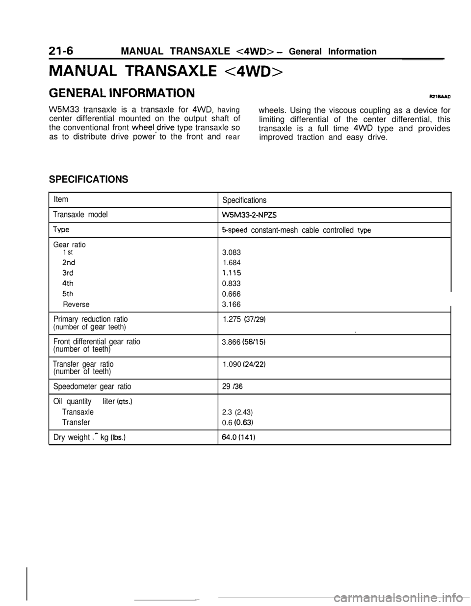
W5M33 transaxle is a transaxle for 4WD, having
center differential mounted on the output shaft ofwheels. Using the viscous coupling as a device for
the conventional front
wheeledrive type transaxle solimiting differential of the center differential, this
as to distribute drive power to the front and reartransaxle is a full time 4WD type and provides
improved traction and easy drive.
SPECIFICATIONS
Item
Transaxle model
We
Gear ratio
1 St
2nd
3rd4th5th
Reverse
Primary reduction ratio
(number of gear teeth)
Front differential gear ratio
(number of teeth)Specifications
W5M33-2-NPZS
5-speed constant-mesh cable controlled type3.083
1.684
7.1150.833
0.666
3.166
1.275 (37/29).
3.866 (58/l
51
Transfer gear ratio(number of teeth)1.090 (24/22)
Speedometer gear ratio
Oil quantity
liter (qts.)
Transaxle
Transfer
Dry weight ic kg (Ibs.)
29 I36
2.3 (2.43)0.6
(0.63)
64.0(141)