MITSUBISHI ECLIPSE 1990 Service Manual
Manufacturer: MITSUBISHI, Model Year: 1990, Model line: ECLIPSE, Model: MITSUBISHI ECLIPSE 1990Pages: 391, PDF Size: 15.27 MB
Page 331 of 391
BODY - Main Body23-13
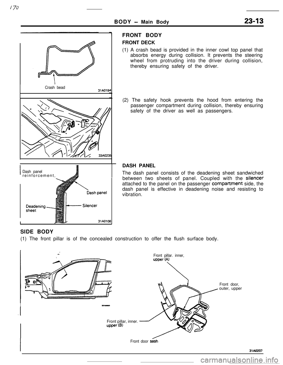
Crash bead31AO19
IDash panelreinforcement,
I31AO109FRONT BODY
FRONT DECK
(1) A crash bead is provided in the inner cowl top panel that
absorbs energy during collision. It prevents the steering
wheel from protruding into the driver during collision,
thereby ensuring safety of the driver.
(2) The safety hook prevents the hood from entering the
passenger compartment during collision, thereby ensuring
safety of the driver as well as passengers.
DASH PANEL
The dash panel consists of the deadening sheet sandwiched
between two sheets of panel. Coupled with the silencer
attached to the panel on the passenger
companment side, the
dash panel is effective in deadening noise and resisting to
vibration.SIDE BODY
(1) The front pillar is of the concealed construction to offer the flush surface body.
IU-Front pillar, inner.upper(B)
Front pillar. inner,upper (A)
Front door,outer, upper
Front door s&h
Page 332 of 391
BODY - Main Body23-15MAINTENANCE SERVICEABILITY
;ide Structure
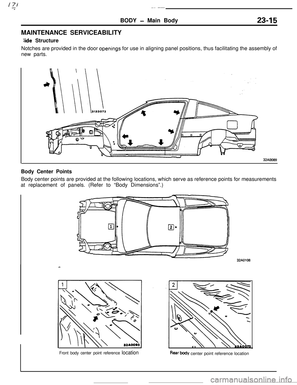
Notches are provided in the door
openings for use in aligning panel positions, thus facilitating the assembly of
new parts.
32AOO89Body Center Points
Body center points are provided at the following locations, which serve as reference points for measurements
at replacement of panels. (Refer to “Body Dimensions”.)32A0108
Front body center point reference locationRear body center point reference location
Page 333 of 391
_.-
23-16BODY - Main Bodv
Access Holes
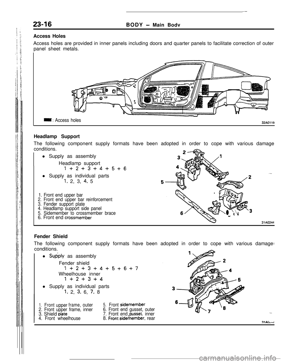
Access holes are provided in inner panels including doors and quarter panels to facilitate correction of outer
panel sheet metals.
= : Access holes32AO119Headlamp Support
The following component supply formats have been adopted in order to cope with various damage
conditions.l Supply as assembly
‘+j
3,Headlamp support
1+2+3+4+5+6l Supply as individual parts
1. 2, 3, 4. 5
1. Front end upper bar
2. Front end upper bar reinforcement
3. Fender support plate
4. Headlamp support side panel
5. Sidemember to crossmember brace
c?jpaiig3L
6. Front end crossmemberl r;‘4
I31AO244Fender Shield
The following component supply formats have been adopted in order to cope with various damage
conditions.
l Supply as assembly
Fender shield
1+2+3+4+5+6+7Wheelhouse inner
1+2+3+4l Supply as individual parts
1. 2, 3. 6, 7. 8
1.Frontupperframe,outer5.Frontsidemember6
2. Front upper frame, inner
3. Shield elate
6. Front end gusset, outer
7. Front end ausset. inner
I4. Front wheelhouse8. Front sidemember. rear
Page 334 of 391
BODY - Main Bodv
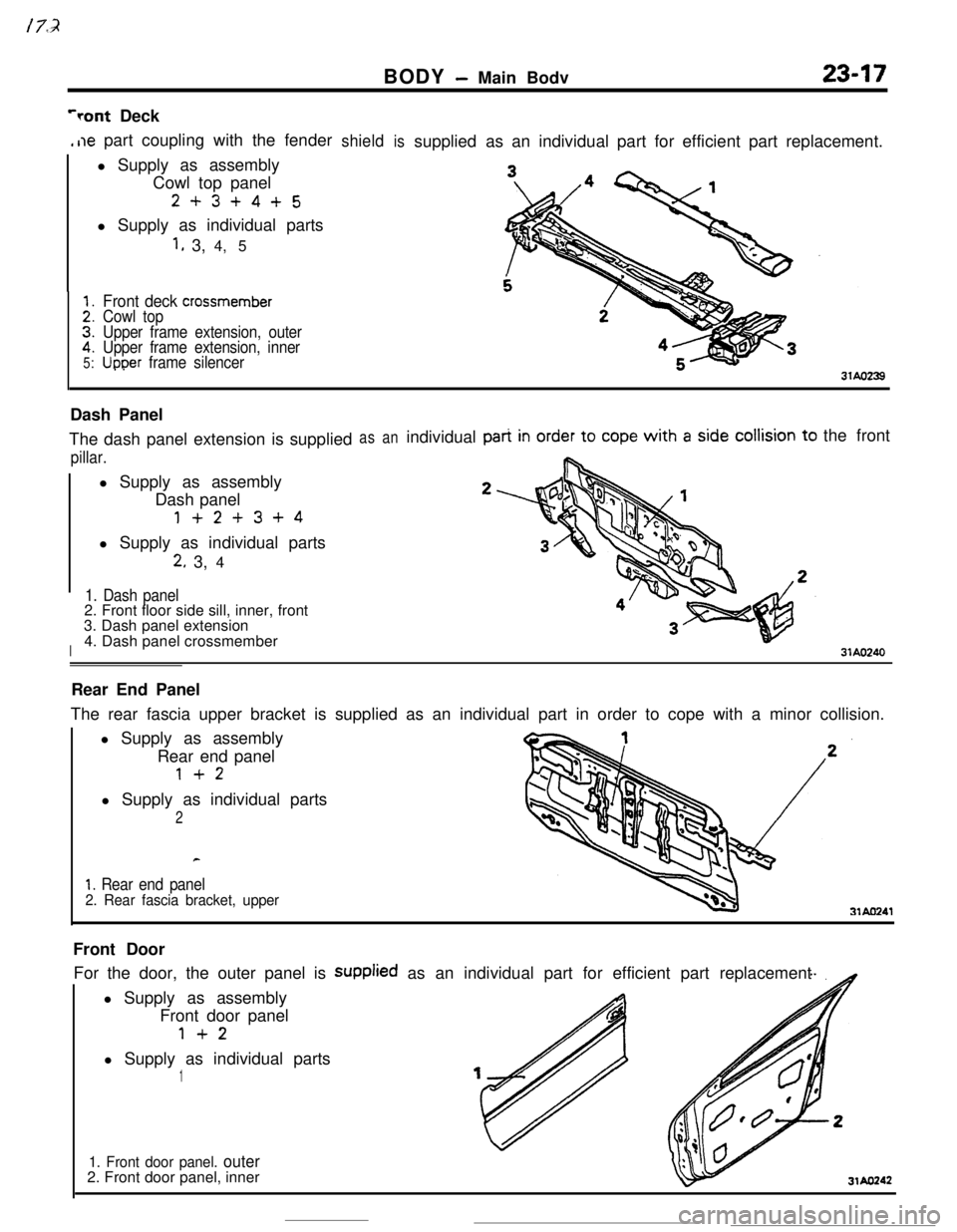
‘rant Deck,he part coupling with the fender
l Supply as assembly
Cowl top panel
2+3+4+5l Supply as individual parts
1, 3, 4, 5
::2.
5:
Front deck crossmemberCowl top
Upper frame extension, outer
Upper frame extension, inner
Uooer frame silencer
shieldissuppliedas an individual part for efficient part replacement.
Dash Panel
The dash panel extension is supplied
pillar.l Supply as assembly
Dash panel
1+2+3+4l Supply as individual parts
2. 3, 4
1. Dash panel2. Front floor side sill, inner, front
I3. Dash panel extension
4. Dash panel crossmember
asanindividualthe front
31AO240Rear End Panel
The rear fascia upper bracket is supplied as an individual part in order to cope with a minor collision.
l Supply as assembly
Rear end panel
1+2l Supply as individual parts
2
1. Rear end panel2. Rear fascia bracket, upper31AO241Front Door
For the door, the outer panel is supplied as an individual part for efficient part replacement
l Supply as assembly
Front door panel
1+2l Supply as individual parts
1
1. Front door panel. outer2. Front door panel, inner
31AO242
Page 335 of 391
23-18BODY -Body Color Code / Body Color Code Interpretation / Solid
izsiii
Noofl -ENGINE -TNANS I
coLm %F
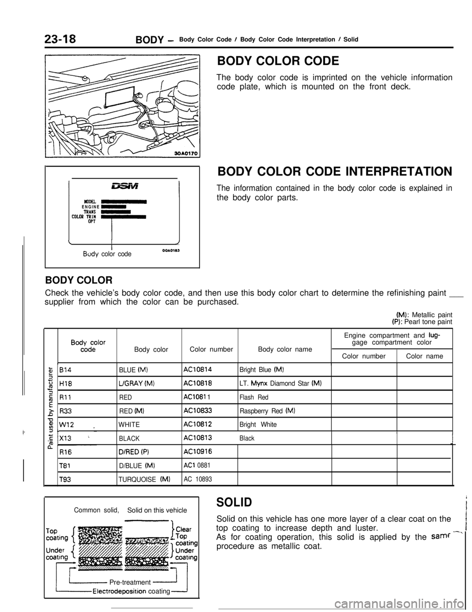
-T-iI/IBody color code0010163BODY COLOR CODE
The body color code is imprinted on the vehicle information
code plate, which is mounted on the front deck.
BODY COLOR CODE INTERPRETATION
The information contained in the body color code is explained inthe body color parts.
BODY COLOR
Check the vehicle’s body color code, and then use this body color chart to determine the refinishing paint ___
supplier from which the color can be purchased.(M): Metallic paint
(P): Pearl tone paint
B”%d:‘orBody colorColor numberBody color nameEngine compartment and
lug-gage compartment color
Color numberColor name
,814
H18
Rll
R33
w12 _c
BLUE (MI
UGRAY (Mvt)
RED
RED (MI
WHITE
AC10814
AC10818
AC1081 1
AC10833
AC10812Bright Blue
(MI
LT. Mynx
Diamond Star (MI
Flash Red
Raspberry Red (MI
Bright White
BLACKAC10813Black
n R16
T81
T93
D/RED (PIAC10916
D/BLUE (Ml
AC1 0881
TURQUOISE (MIAC 10893
SOLID
i
Common solid,Solid on this vehicleISolid on this vehicle has one more layer of a clear coat on the
Itop coating to increase depth and luster.
IAs for coating operation, this solid is applied by the samf
-”procedure as metallic coat.
I Pre-treatmentElectrodeposition coating
Page 336 of 391
i73BODY
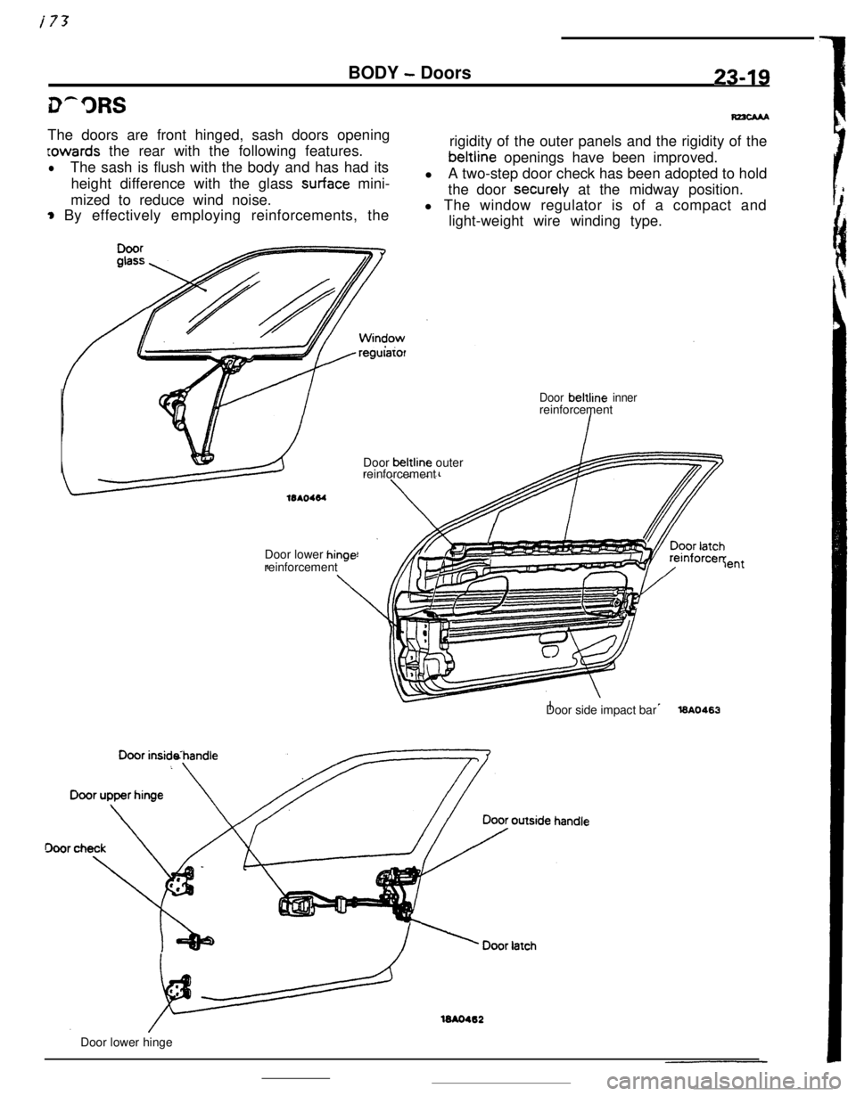
- Doors23-19The doors are front hinged, sash doors opening
Lowards the rear with the following features.
lThe sash is flush with the body and has had its
height difference with the glass
surface mini-
mized to reduce wind noise.
* By effectively employing reinforcements, the
regularorrigidity of the outer panels and the rigidity of thebeltline openings have been improved.
lA two-step door check has been adopted to hold
the door securely at the midway position.
l The window regulator is of a compact and
light-weight wire winding type.
Door beltline innerreinforcement
Door beltline outer
reinforcement
Door lower
hinr-reinforcement *-lentDoor side impact bar
l6A0463
16AO462Door lower hinge
Page 337 of 391
23-20BODY - Central Door LocksCENTRAL DOOR LOCKS
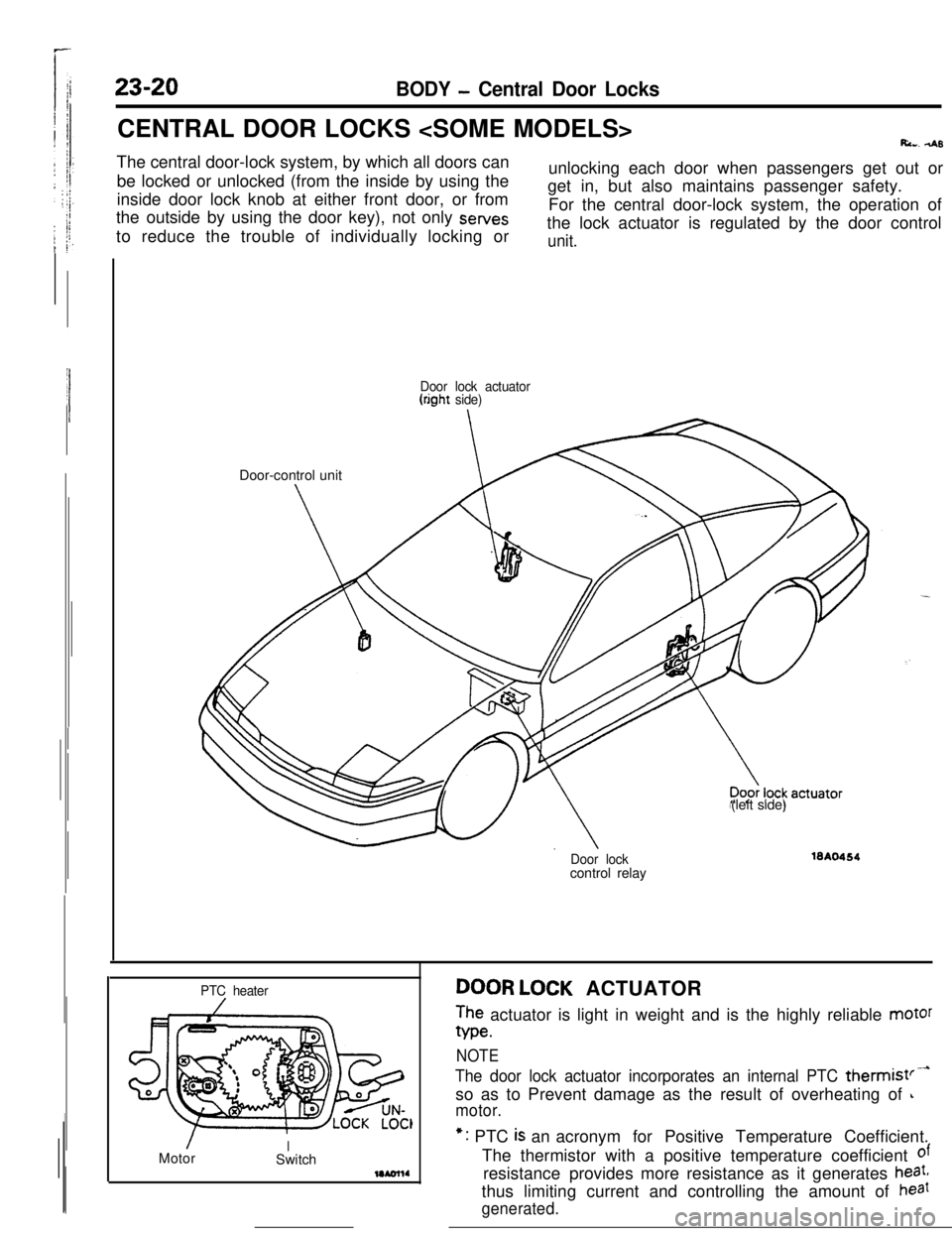
Ri... 4sThe central door-lock system, by which all doors can
be locked or unlocked (from the inside by using the
inside door lock knob at either front door, or from
the outside by using the door key), not only sewes
to reduce the trouble of individually locking orunlocking each door when passengers get out or
get in, but also maintains passenger safety.
For the central door-lock system, the operation of
the lock actuator is regulated by the door control
unit.
Door lock actuator(right side)Door-control unit
(left side)
Door lockcontrol relay16A0464
PTC heater
/MotorISwitchDOOR LOCK ACTUATOR
The actuator is light in weight and is the highly reliable motor
We.
NOTE
The door lock actuator incorporates an internal PTC thermist’-so as to Prevent damage as the result of overheating of
L
motor.*: PTC
is an acronym for Positive Temperature Coefficient.
The thermistor with a positive temperature coefficient
ofresistance provides more resistance as it generates
heat,thus limiting current and controlling the amount of
haat
generated.
Page 338 of 391
BODY - Central Door Locks23-21
IBattery
1IJDoor lock 4Door lockactuator t(left side)actuator
(right side) -Battery
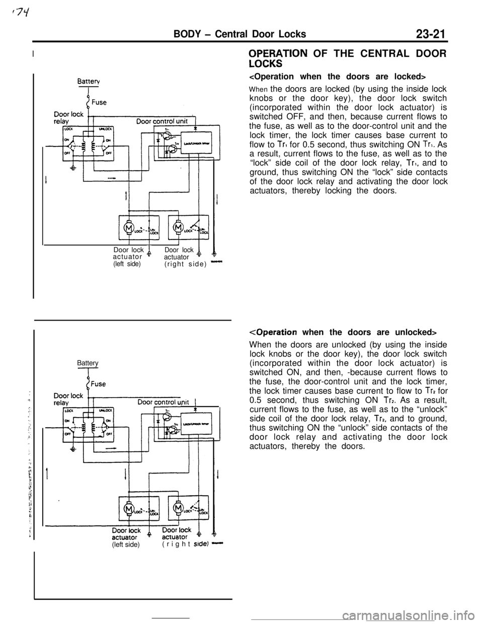
Init !,WF%;$TlON OF THE CENTRAL DOOR
When the doors are locked (by using the inside lock
knobs or the door key), the door lock switch
(incorporated within the door lock actuator) is
switched OFF, and then, because current flows to
the fuse, as well as to the door-control unit and the
lock timer, the lock timer causes base current to
flow to
TrI for 0.5 second, thus switching ON Tr,. As
a result, current flows to the fuse, as well as to the
“lock” side coil of the door lock relay,
Tr,, and to
ground, thus switching ON the “lock” side contacts
of the door lock relay and activating the door lock
actuators, thereby locking the doors.
When the doors are unlocked (by using the inside
lock knobs or the door key), the door lock switch
(incorporated within the door lock actuator) is
switched ON, and then, -because current flows to
the fuse, the door-control unit and the lock timer,
the lock timer causes base current to flow to
Tr? for
0.5 second, thus switching ON
Tr7. As a result,
current flows to the fuse, as well as to the “unlock”
side coil of the door lock relay,
Trp, and to ground,
thus switching ON the “unlock” side contacts of the
door lock relay and activating the door lock
actuators, thereby the doors.
(left side)(right
side) -
Page 339 of 391
23-22BODY - Power Windows
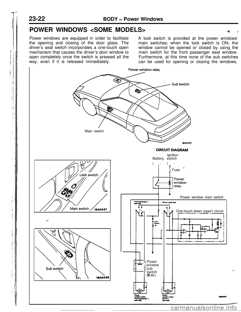
POWER WINDOWS
R’1Power windows are equipped in order to facilitate
A lock switch is provided at the power windows’
the opening and closing of the door glass. The
main switches; when the lock switch is ON, the
driver’s seat switch incorporates a one-touch open
mechanism that causes the driver’s door window towindow cannot be opened or closed by using the
main switch for the front passenger seat window.
open completely once the switch is pressed all the
way, even if it is released immediately.Furthermore, at this time none of the sub switches
can be used for opening or closing the windows,
Main switch
CIRCUIT DIAGRAMIgnition
Battery switch
l-l-
’ 1Fuse ’
Z*,“““”CrPower window main switch
-*W(WlI. _;:
r-
L
--e.
.
I
ELnA
I
Powerwindow
subswitch
(R.H.)
I IOne-touch down (open) circuit
--P’-‘-,
-
Page 340 of 391
BODY - Power Windows23-23
IBatterv
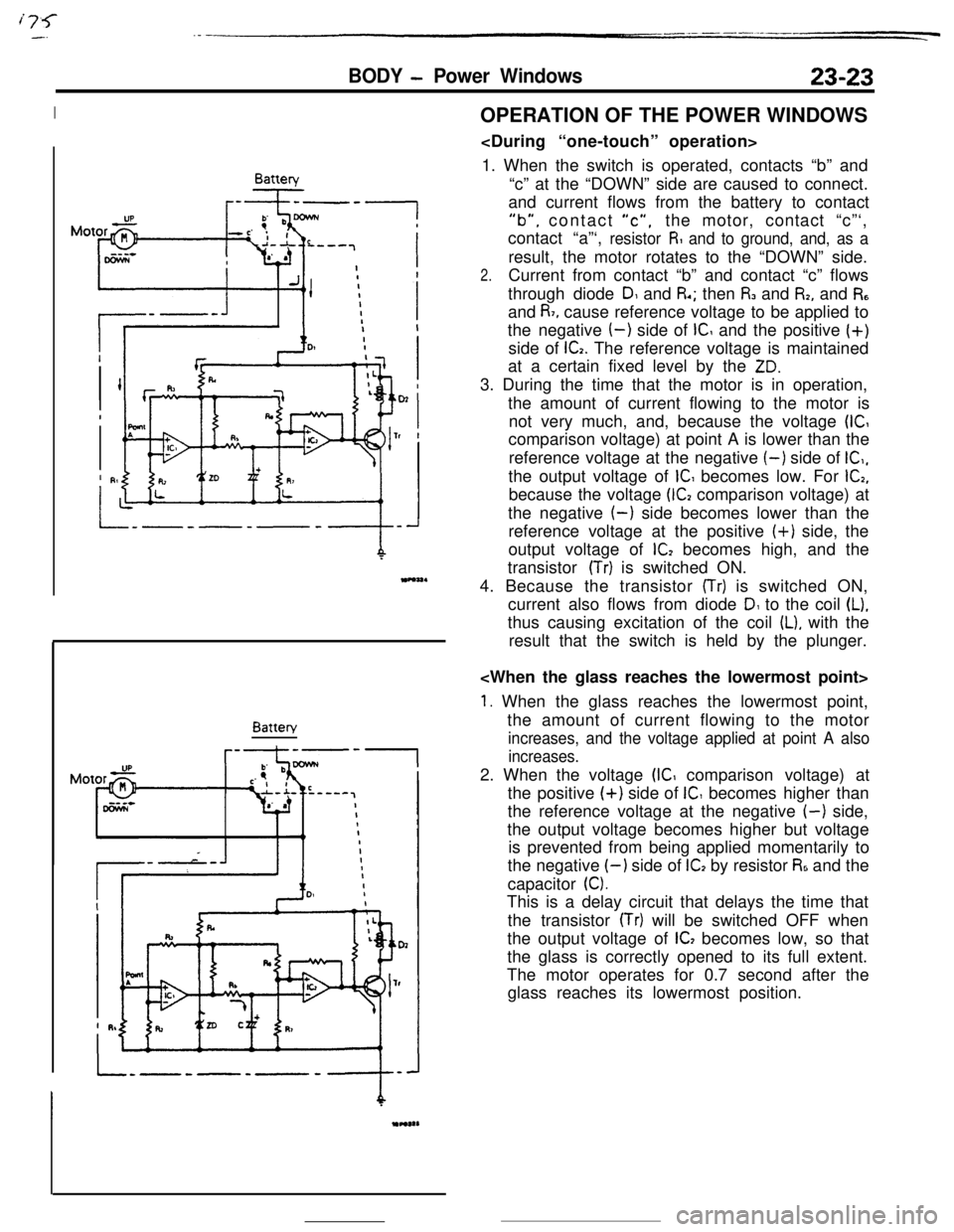
---IBatteryOPERATION OF THE POWER WINDOWS
1. When the switch is operated, contacts “b” and
“c” at the “DOWN” side are caused to connect.
and current flows from the battery to contact
“b”, contact “c”,the motor, contact “c”‘,
contact “a”‘,
resistor R and to ground, and, as aresult, the motor rotates to the “DOWN” side.
2.Current from contact “b” and contact “c” flows
through diode
DI and R.; then I% and I%, and R,and
R7, cause reference voltage to be applied to
the negative
(-) side of IC and the positive (+)
side of
G. The reference voltage is maintained
at a certain fixed level by the
ZD.3. During the time that the motor is in operation,
the amount of current flowing to the motor is
not very much, and, because the voltage
(ICcomparison voltage) at point A is lower than the
reference voltage at the negative
(-) side of IC,,the output voltage of
IC becomes low. For G,because the voltage
(G comparison voltage) at
the negative
(-) side becomes lower than the
reference voltage at the positive (+) side, the
output voltage of
lC2 becomes high, and the
transistor
(Tr) is switched ON.
4. Because the transistor
(Tr) is switched ON,
current also flows from diode
D1 to the coil (L).thus causing excitation of the coil
IL), with the
result that the switch is held by the plunger.
1. When the glass reaches the lowermost point,
the amount of current flowing to the motor
increases, and the voltage applied at point A also
increases.2. When the voltage
(IC comparison voltage) at
the positive
(+) side of IC becomes higher than
the reference voltage at the negative
(-) side,
the output voltage becomes higher but voltage
is prevented from being applied momentarily to
the negative
I-) side of ICI by resistor R6 and the
capacitor
0.This is a delay circuit that delays the time that
the transistor
(Tr) will be switched OFF when
the output voltage of
IC, becomes low, so that
the glass is correctly opened to its full extent.
The motor operates for 0.7 second after the
glass reaches its lowermost position.