torque MITSUBISHI ECLIPSE 1991 Service Manual
[x] Cancel search | Manufacturer: MITSUBISHI, Model Year: 1991, Model line: ECLIPSE, Model: MITSUBISHI ECLIPSE 1991Pages: 1216, PDF Size: 67.42 MB
Page 964 of 1216

-m-m AUTOMATIC TRANSAXLE -Transaxle Assembly
DISASSEMBLYN21WMCaution
%T1. Since the automatic transaxle is made of particularly
~_,high precision parts, be very careful when handling
them during disassembly and reassembly so that they
are not scratched.
2. Spread a rubber mat on the workbench and keep it
clean.3. Do not use cotton gloves or cloth rags during dis-
assembly. If they are needed, use nylon cloth or paper
towels.
4. Clean all disassembled parts. Clean metal
parts with
normal cleanser and completely dry with air.
5. Clean the clutch disc, resin thrust plate and rubber
parts with ATF (automatic transmission fluid) and do
not get any dirt on them.
6. If the transaxle itself is damaged, disassemble and
clean the cooler system also.
1. Remove the torque converter.
2. Mount the dial gauge on the transaxle case and measure
the end play of the input shaft.
3. Remove the brackets.
4. Remove the oil level gauge and oil level gauge guide.
1:5. Remove the pulse generator A and B.
6.First remove the manual control lever and then remove theinhibitor switch.
7. Remove the speedometer driven gear assembly.
Page 976 of 1216
21-282 AUTOMATIC TRANSAXLE - Transaxle Assembly
\TFAOi57
AWDTFAOl63
bearing retainerTFA0156
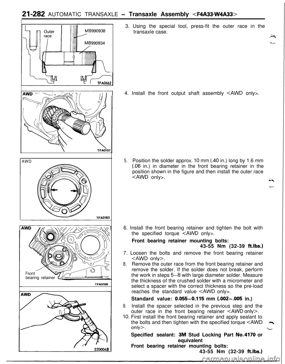
13. Using the special tool, press-fit the outer race in the
transaxle case.
4. Install the front output shaft assembly
5.Position the solder approx. 10 mm (.40 in.) long by 1.6 mm
(.06 in.) in diameter in the front bearing retainer in the
position shown in the figure and then install the outer race
cAWD only>.A6. Install the front bearing retainer and tighten the bolt with
the specified torque
Front bearing retainer mounting bolts:
43-55 Nm (32-39
ft.lbs.)7. Loosen the bolts and remove the front bearing retainer
8.Remove the outer race from the front bearing retainer and
remove the solder. If the solder does not break, perform
the work in steps
5-8 with large diameter solder. Measure
the thickness of the crushed solder with a micrometer and
select a spacer with the correct thickness so the pre-load
reaches the standard value
Standard value:
0.055-0.115 mm (.002-.005 in.)
9.Install the spacer selected in the previous step and the
outer race in the front bearing retainer
10. First install the front bearing retainer and apply sealant to
the bolts and then tighten with the specified torque
equivalent
Front bearing retainer mounting bolts:
43-55 Nm (32-39
ftlbs.)
Page 978 of 1216
21-284 AUTOMATIC TRANSAXLE - Transaxle Assemblv
//TFAOlSO
TFA0167
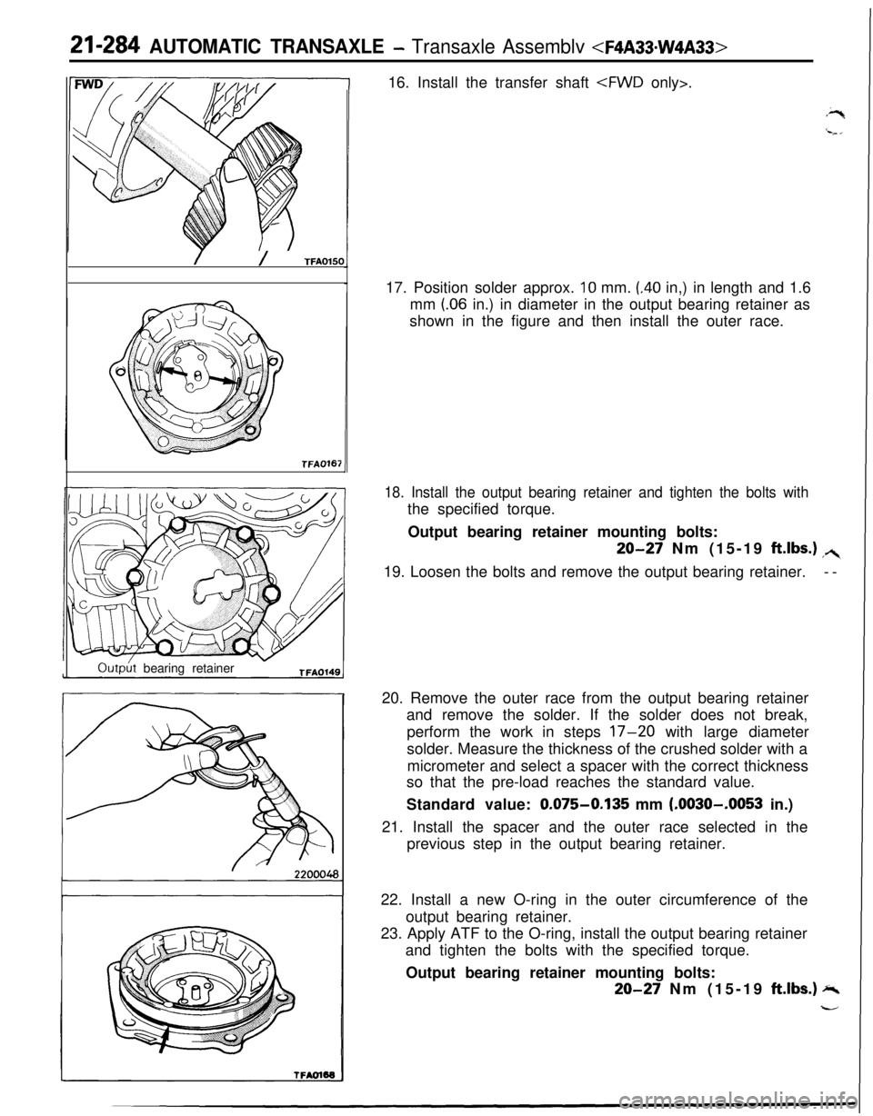
Outph bearing retainerTFAOl4916. Install the transfer shaft
17. Position solder approx.
10 mm. (.40 in,) in length and 1.6
mm
(06 in.) in diameter in the output bearing retainer as
shown in the figure and then install the outer race.
18. Install the output bearing retainer and tighten the bolts withthe specified torque.
Output bearing retainer mounting bolts:
20-27 Nm (15-19 ft.lbs.) ,+19. Loosen the bolts and remove the output bearing retainer.--
20. Remove the outer race from the output bearing retainer
and remove the solder. If the solder does not break,
perform the work in steps
17-20 with large diameter
solder. Measure the thickness of the crushed solder with a
micrometer and select a spacer with the correct thickness
so that the pre-load reaches the standard value.
Standard value:
0.075-0.135 mm (.0030--0053 in.)
21. Install the spacer and the outer race selected in the
previous step in the output bearing retainer.
22. Install a new O-ring in the outer circumference of the
output bearing retainer.
23. Apply ATF to the O-ring, install the output bearing retainer
and tighten the bolts with the specified torque.
Output bearing retainer mounting bolts:
20-27 Nm (15-19 ft.lbs.) -
-
Page 986 of 1216
21-292 AUTOMATIC TRANSAXLE - Transaxle Assembly
cover
I
TFAOl2r
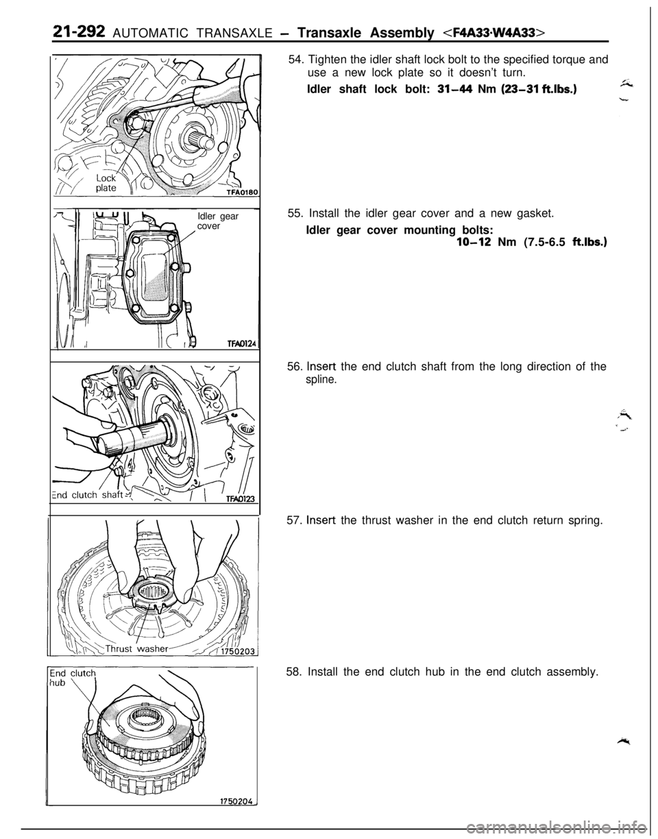
17502XJ54. Tighten the idler shaft lock bolt to the specified torque and
use a new lock plate so it doesn’t turn.
Idler shaft lock bolt:
31-44 Nm (23-31 ft.lbs.)55. Install the idler gear cover and a new gasket.
Idler gear cover mounting bolts:
lo-12 Nm (7.5-6.5 ftlbs.)56.
Insert the end clutch shaft from the long direction of the
spline.57.
Insert the thrust washer in the end clutch return spring.
58. Install the end clutch hub in the end clutch assembly.
Page 987 of 1216
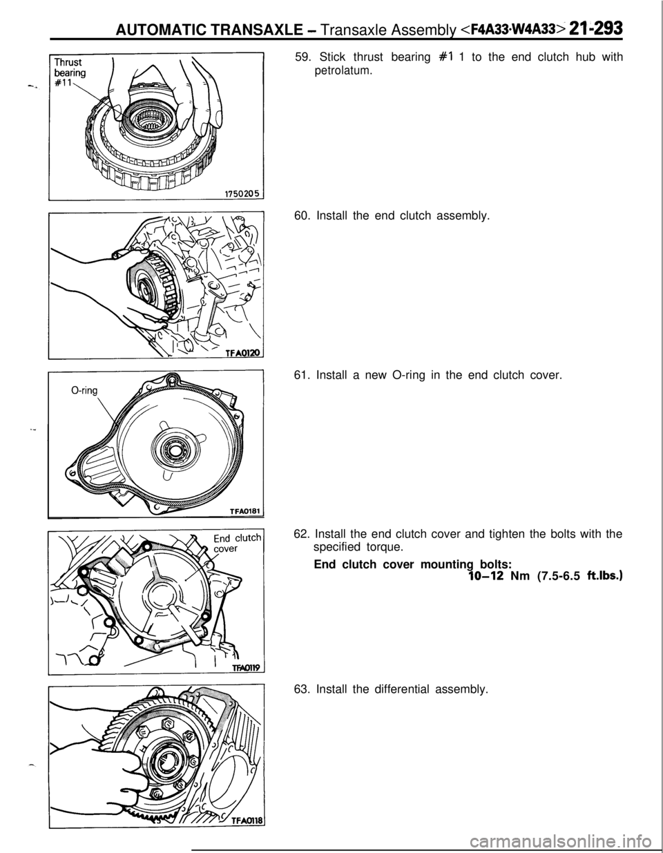
AUTOMATIC TRANSAXLE - Transaxle Assembly
petrolatum.60. Install the end clutch assembly.
61. Install a new O-ring in the end clutch cover.
62. Install the end clutch cover and tighten the bolts with the
specified torque.
End clutch cover mounting bolts:
IO-12 Nm (7.5-6.5 ftlbs.)63. Install the differential assembly.
Page 988 of 1216
21-294 AUTOMATIC TRANSAXLE - Transaxle Assemblv
‘/TFAOl16
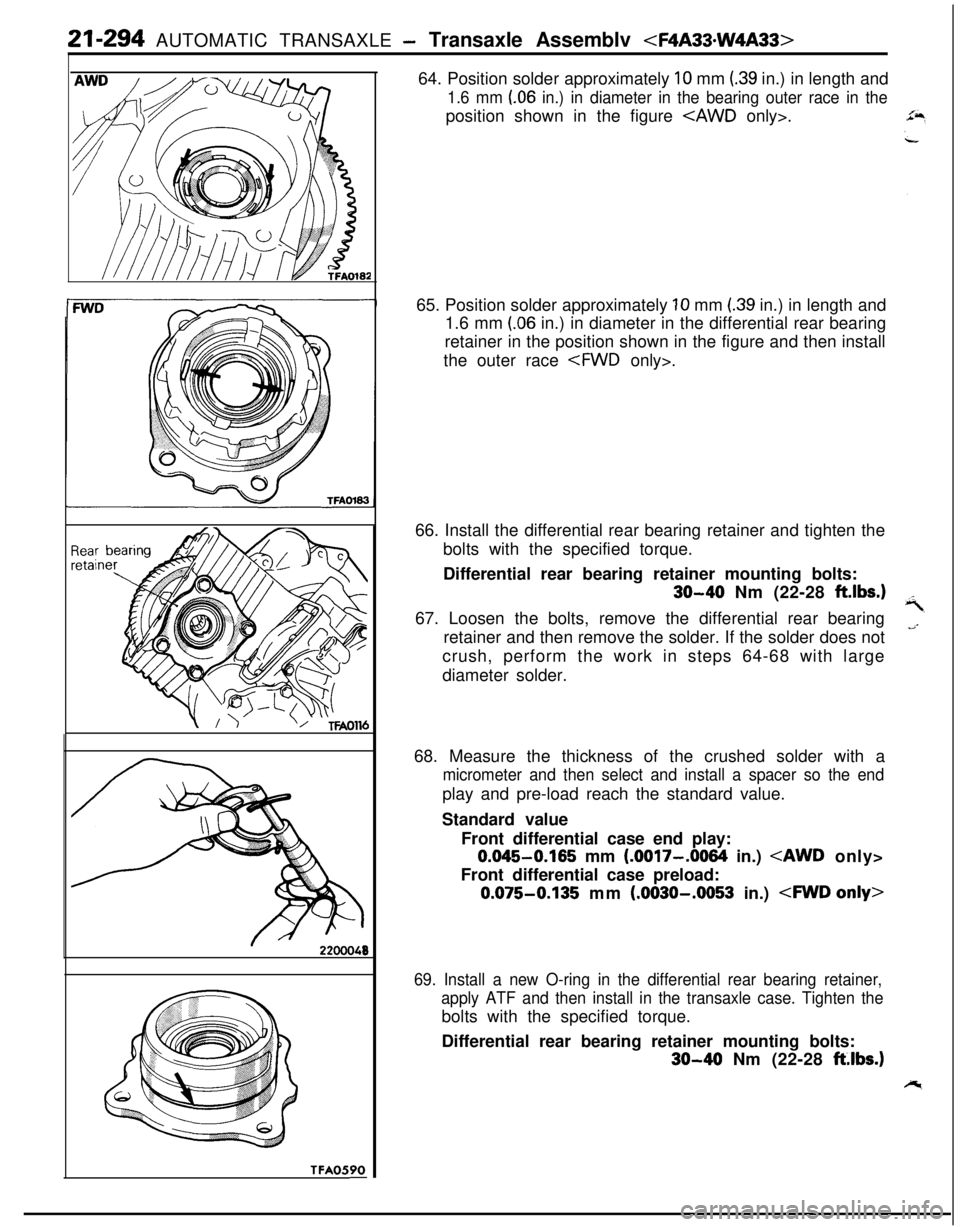
TFA0590-64. Position solder approximately
10 mm (39 in.) in length and
1.6 mm (06 in.) in diameter in the bearing outer race in theposition shown in the figure
65. Position solder approximately
10 mm (39 in.) in length and
1.6 mm
(.06 in.) in diameter in the differential rear bearing
retainer in the position shown in the figure and then install
the outer race
66. Install the differential rear bearing retainer and tighten the
bolts with the specified torque.
Differential rear bearing retainer mounting bolts:
30-40 Nm (22-28 ft.lbs.167. Loosen the bolts, remove the differential rear bearing
retainer and then remove the solder. If the solder does not
crush, perform the work in steps 64-68 with large
diameter solder.
68. Measure the thickness of the crushed solder with a
micrometer and then select and install a spacer so the endplay and pre-load reach the standard value.
Standard value
Front differential case end play:
0.045-0.165 mm (.0017-.0064 in.)
Front differential case preload:
0.075-0.135 mm (.0030-.0053 in.)
69. Install a new O-ring in the differential rear bearing retainer,
apply ATF and then install in the transaxle case. Tighten thebolts with the specified torque.
Differential rear bearing retainer mounting bolts:
30-40 Nm (22-28 ft.lbs.)
Page 989 of 1216
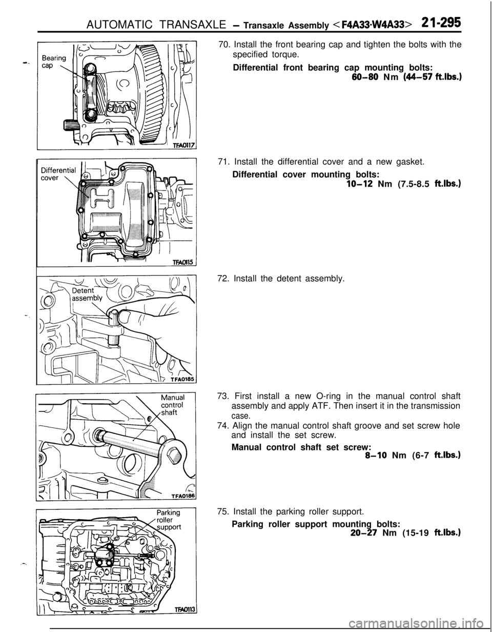
AUTOMATIC TRANSAXLE - Transaxle Assembly < F4A33*w4A33>2 I-29570. Install the front bearing cap and tighten the bolts with the
specified torque.
Differential front bearing cap mounting bolts:
60-80 Nm (44-57 ft.lbs.)71. Install the differential cover and a new gasket.
Differential cover mounting bolts:
IO-12 Nm (7.5-8.5 ft.lbs.)72. Install the detent assembly.
73. First install a new O-ring in the manual control shaft
assembly and apply ATF. Then insert it in the transmission
case.74. Align the manual control shaft groove and set screw hole
and install the set screw.
Manual control shaft set screw:
8-10 Nm (6-7 ft.lbs.)75. Install the parking roller support.
Parking roller support mounting bolts:
20-27 Nm (15-19 ft.lbs.1
Page 990 of 1216

21-296 AUTOMATIC TRANSAXLE - Transaxle Assembly
77. Install an O-ring in the O-ring groove on top of the valve
body assembly.
78. Replace the solenoid valve harness grommet O-ring with anew O-ring.
79. Pass the solenoid valve connector through from the inside
of the transaxle case hole.
80. Insert the solenoid valve harness grommet in the case hole.,**%4
81. Temporarily install the valve body while inserting the detentplate pin in the manual valve groove. Then install the oil
temperature sensor and holder and tighten the bolts with
the specified torque.
A bolt
= 18 mm (.71 in.)
B bolt = 25 mm (.98 in.)
C bolt = 40 mm (1.57 in.)
Valve body assembly mounting bolts:
lo-12 Nm (7.5-8.5 fklbs.)
Caution
Fix the solenoid valve and oil temperature sensor
harness securely in the position shown.
82. Install the oil filter.
Oil filter mounting bolts: 5-7 Nm (4-5
ft.lbs.1
Page 992 of 1216
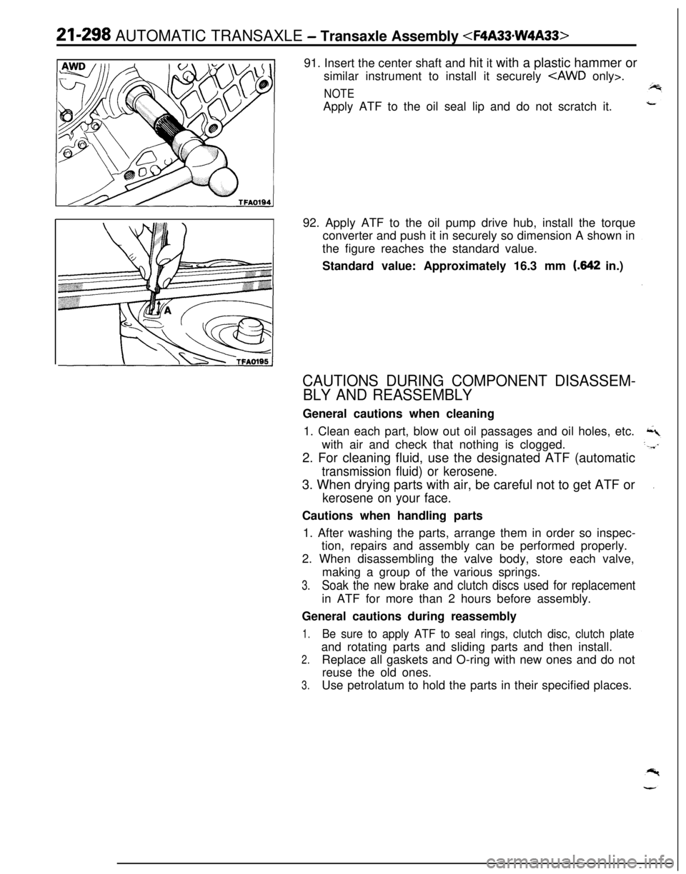
21-298 AUTOMATIC TRANSAXLE - Transaxle Assembly
similar instrument to install it securely
NOTEApply ATF to the oil seal lip and do not scratch it.
92. Apply ATF to the oil pump drive hub, install the torque
converter and push it in securely so dimension A shown in
the figure reaches the standard value.
Standard value: Approximately 16.3 mm
(.642 in.)
CAUTIONS DURING COMPONENT DISASSEM-
BLY AND REASSEMBLYGeneral cautions when cleaning
1. Clean each part, blow out oil passages and oil holes, etc.
with air and check that nothing is clogged.
2. For cleaning fluid, use the designated ATF (automatic
transmission fluid) or kerosene.3. When drying parts with air, be careful not to get ATF or
kerosene on your face.Cautions when handling parts
1. After washing the parts, arrange them in order so inspec-
tion, repairs and assembly can be performed properly.
2. When disassembling the valve body, store each valve,
making a group of the various springs.
3.Soak the new brake and clutch discs used for replacementin ATF for more than 2 hours before assembly.
General cautions during reassembly
1.Be sure to apply ATF to seal rings, clutch disc, clutch plateand rotating parts and sliding parts and then install.
2.Replace all gaskets and O-ring with new ones and do not
reuse the old ones.
3.Use petrolatum to hold the parts in their specified places.
Page 994 of 1216
21-300AUTOMATIC TRANSAXLE - Oil Pump
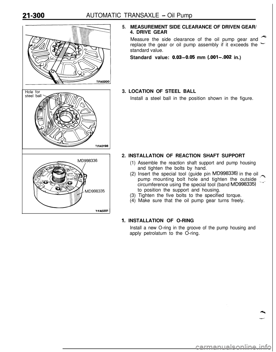
5.MEASUREMENT SIDE CLEARANCE OF DRIVEN GEAR/
4. DRIVE GEAR
Measure the side clearance of the oil pump gear and *A
replace the gear or oil pump assembly if it exceeds the
-’standard value.
Standard value:
0.03-0.05 mm (.OOl-.002 in.)
3. LOCATION OF STEEL BALL
Install a steel ball in the position shown in the figure.
2. INSTALLATION OF REACTION SHAFT SUPPORT
(1) Assemble the reaction shaft support and pump housingand tighten the bolts by hand.
(2) Insert the special tool (guide pin
MD998336) in the oil ;?pump mounting bolt hole and tighten the outside
‘II.circumference using the special tool (band
MD9983351to position the support and housing.
(3) Tighten the five bolts to the specified torque.
(4) Make sure that the oil pump gear turns freely.
ITFA0201
1
1. INSTALLATION OF O-RING
Install a new O-ring in the groove of the pump housing andapply petrolatum to the O-ring.