torque MITSUBISHI ECLIPSE 1991 Service Manual
[x] Cancel search | Manufacturer: MITSUBISHI, Model Year: 1991, Model line: ECLIPSE, Model: MITSUBISHI ECLIPSE 1991Pages: 1216, PDF Size: 67.42 MB
Page 1047 of 1216
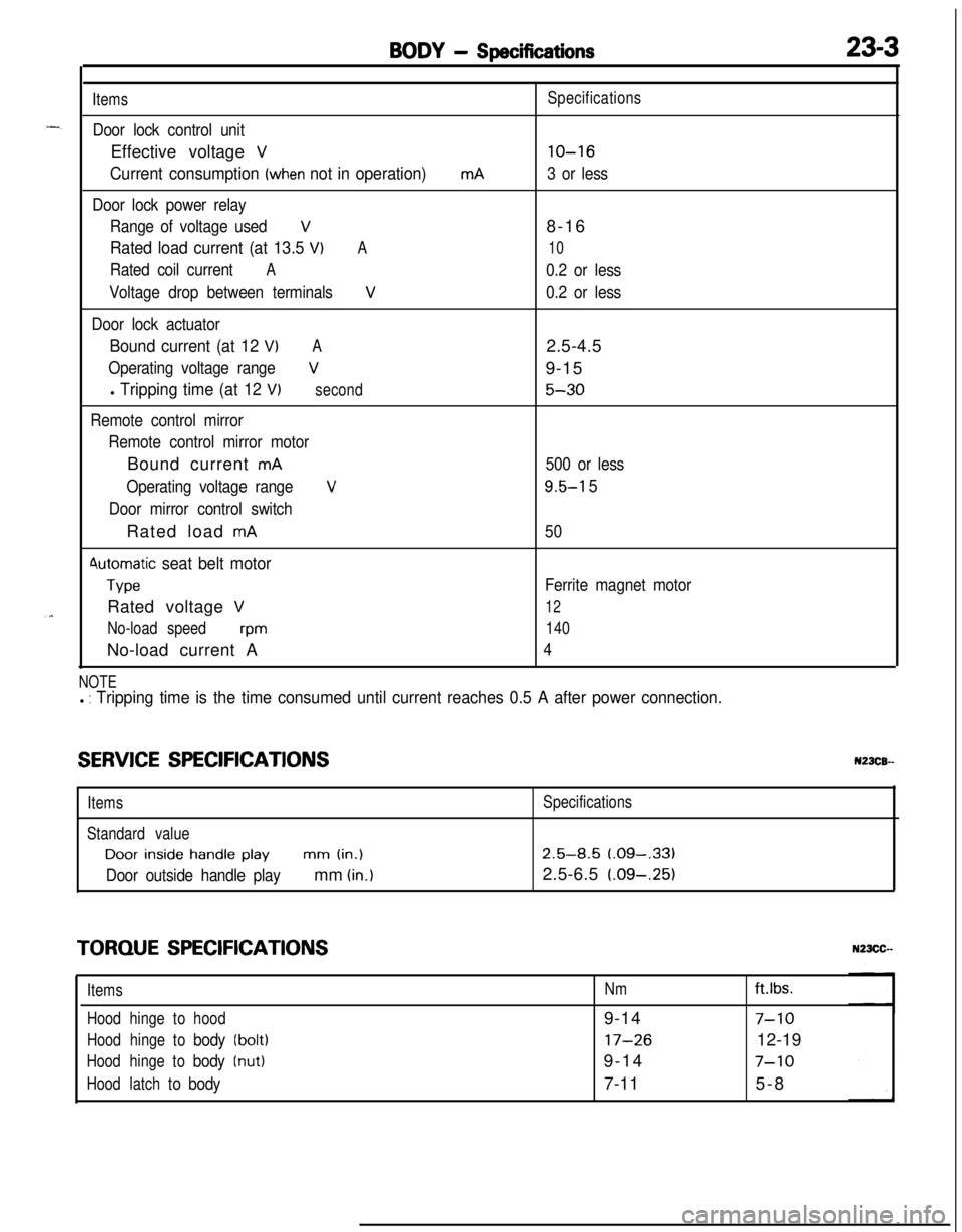
BODY - Specifications23-3
Items
Door lock control unitEffective voltage
V
Current consumption (when not in operation)
Door lock power relay
Range of voltage used
V
Rated load current (at 13.5 VIA
Rated coil currentA
Voltage drop between terminalsV
Door lock actuator
Bound current (at 12 VIA
Operating voltage rangeV
l Tripping time (at 12 V)second
Remote control mirror
Remote control mirror motorBound current
mA
Operating voltage range
V
Door mirror control switchRated load
mA
4utomatic seat belt motor
TypeRated voltage
V
No-load speedwmNo-load current A
mASpecifications
lo-16
3 or less8-16
10
0.2 or less
0.2 or less2.5-4.5
9-15
5-30
500 or less
9.5-l 5
50
Ferrite magnet motor
12
140
4
NOTEl : Tripping time is the time consumed until current reaches 0.5 A after power connection.
SERVICE SPECIFICATIONSN23CB--
ItemsSpecifications
Standard valueDoor
inside handle playmm (in.)2.5-8.5 (.09-,331
Door outside handle playmm (in.)2.5-6.5 (.09-.25)
TORQUE SPECIFICATIONS
ItemsNmft.lbs.
Hoodhingetohood9-14
7-10
Hoodhingetobody(bolt)17-2612-19
Hoodhingetobody(nut)9-147-10
Hoodlatchtobody7-115-8
Page 1095 of 1216
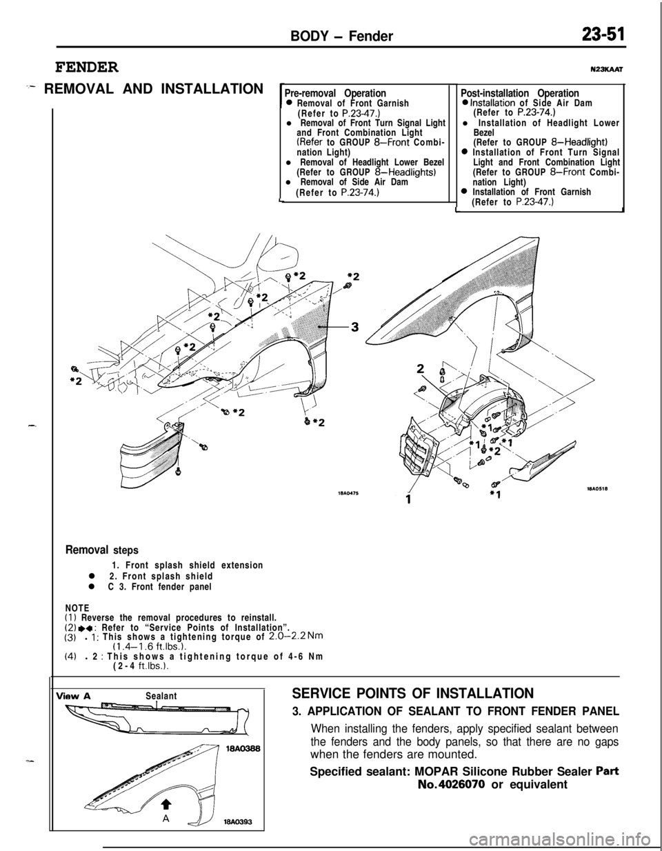
BODY - Fender
FENDER
:- REMOVAL AND INSTALLATION
-.
Pre-removal Operation0 Removal of Front Garnish
(Refer to P.23-47.)l Removal of Front Turn Signal Light
and Front Combination Light
(Refer to GROUP 8-Front Combi-
nation Light)
l Removal of Headlight Lower Bezel
(Refer to GROUP
8-Headlights)l Removal of Side Air Dam
(Refer to
P.23-74.)LLu23KAAr
Post-installation Operation0 Installation of Side Air Dam
(Refer to P.23-74.)l Installation of Headlight Lower
Bezel
(Refer to GROUP
8-Headlight)0 Installation of Front Turn Signal
Light and Front Combination Light
(Refer to GROUP
8-Front Combi-
nation Light)
0 Installation of Front Garnish
(Refer to P.23-47.)J
Removal steps1. Front splash shield extension
l 2. Front splash shield
l C 3. Front fender panel
NOTE
(1) Reverse the removal procedures to reinstall.(2) .a : Refer to “Service Points of Installation”.
(3)l 1 : This shows a tightening torque of 2.0-2.2 Nm(1 .4-l .6 ft.lbs.1.(4)l 2 : This shows a tightening torque of 4-6 Nm
(2-4 ft.lbs.1.
View ASealantSERVICE POINTS OF INSTALLATION
3. APPLICATION OF SEALANT TO FRONT FENDER PANEL
When installing the fenders, apply specified sealant between
the fenders and the body panels, so that there are no gapswhen the fenders are mounted.
Specified sealant: MOPAR Silicone Rubber Sealer
PartNo.4026070 or equivalent
Page 1135 of 1216
-
BODY - Front Seat23-91
Bolts
19AO308
FrontFront seat forward
installation bracket
A-A cross-section
Forward tab
.)\&Front seat’s rearz-2 bracketarea mounting
1Lanchor\
coverForward tabB-B cross-section19A0124
Slid; railSlide kail’sreararea mounting
bracketWA0302
SERVICE POINTS OF INSTALLATION
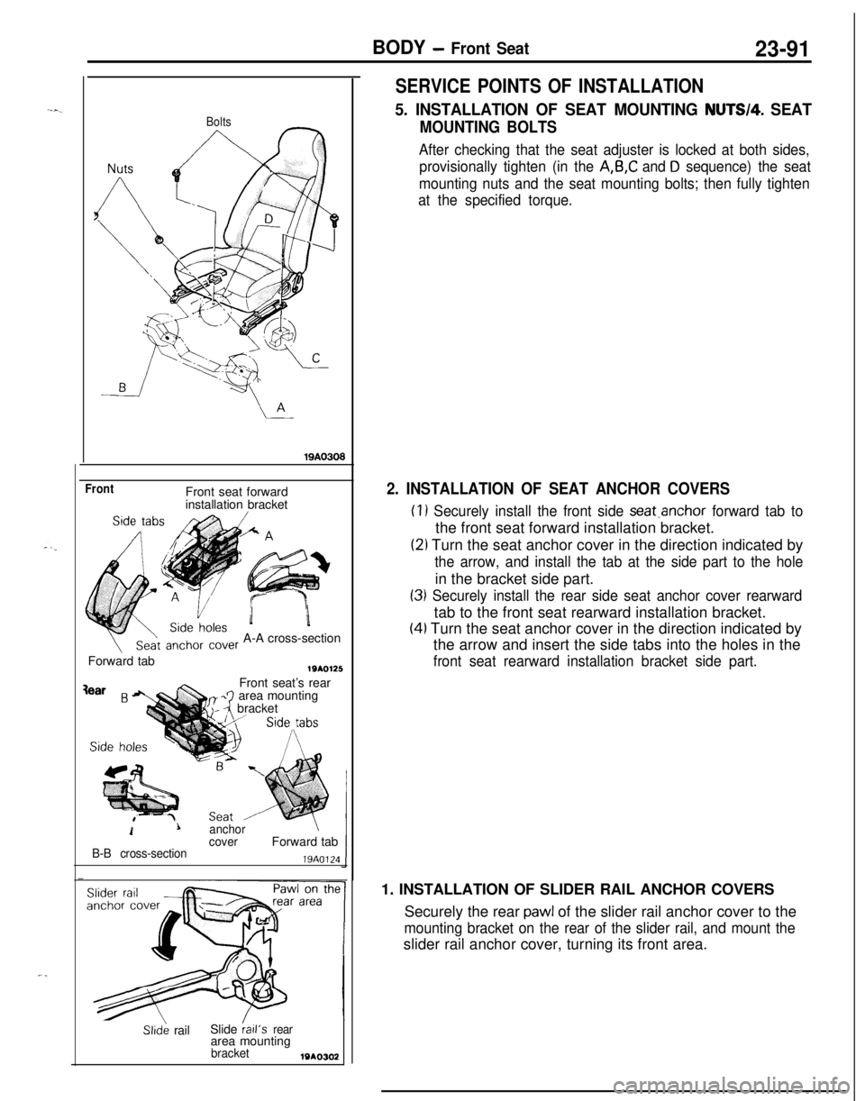
5. INSTALLATION OF SEAT MOUNTING NUTW4. SEAT
MOUNTING BOLTS
After checking that the seat adjuster is locked at both sides,
provisionally tighten (in the
A,B,C and D sequence) the seat
mounting nuts and the seat mounting bolts; then fully tighten
at the specified torque.
2. INSTALLATION OF SEAT ANCHOR COVERS
(1) Securely install the front side seat.anchor forward tab tothe front seat forward installation bracket.
(21 Turn the seat anchor cover in the direction indicated by
the arrow, and install the tab at the side part to the holein the bracket side part.
(3) Securely install the rear side seat anchor cover rearwardtab to the front seat rearward installation bracket.
(4) Turn the seat anchor cover in the direction indicated by
the arrow and insert the side tabs into the holes in the
front seat rearward installation bracket side part.1. INSTALLATION OF SLIDER RAIL ANCHOR COVERS
Securely the rear
pawl of the slider rail anchor cover to the
mounting bracket on the rear of the slider rail, and mount theslider rail anchor cover, turning its front area.
Page 1143 of 1216
BODY - Seat Belt23-99
19AO239
I ITest bulb 2tI
I I
INSPECTION
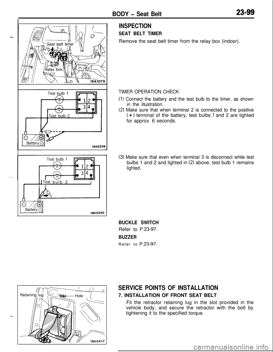
SEAT BELT TIMERRemove the seat belt timer from the relay box (indoor).
TIMER OPERATION CHECK(I
1 Connect the battery and the test bulb to the timer, as shown
in the illustration.
(2) Make sure that when terminal 2 is connected to the positive
(+) terminal of the battery, test bulbs 1 and 2 are lighted
for approx. 6 seconds.
(3) Make sure that even when terminal 3 is disconnect while testbulbs 1 and 2 and lighted in
(2) above, test bulb 1 remains
lighted.
BUCKLE SWITCHRefer to
P.23-97.
BUZZERRefer to
P.23-97.
SERVICE POINTS OF INSTALLATION7. INSTALLATION OF FRONT SEAT BELT
Fit the retractor retaining lug in the slot provided in the
vehicle body, and secure the retractor with the bolt by
tightening it to the specified torque.
Page 1145 of 1216
24-l
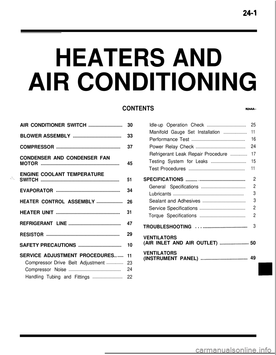
HEATERS ANDAIR CONDITIONING
CONTENTSN24M--AIR CONDITIONER SWITCH
..........................30BLOWER ASSEMBLY
.....................................33
COMPRESSOR.................................................37CONDENSER AND CONDENSER FAN
MOTOR............................................................45ENGINE COOLANT TEMPERATURE
-‘-.,SWITCH............................................................51
EVAPORATOR.................................................
34
HEATERCONTROLASSEMBLY....................
26HEATER UNIT
.................................................31
REFRIGERANTLINE........................................47
RESISTOR........................................................29SAFETY PRECAUTIONS
.................................10SERVICE ADJUSTMENT PROCEDURES..
.....11Compressor Drive
Belt Adjustment
.............
23
CompressorNoise........................................24
Handling
TubingandFittings.......................22Idle-up
OperationCheck..............................25Manifold
GaugeSetInstallation..................11Performance Test
.........................................16Power Relay Check
......................................24Refrigerant Leak Repair Procedure
.............17
TestingSystemforLeaks...........................15Test Procedures
...........................................11
SPECIFICATIONS.............................................2
General Specifications..................................2
Lubricants......................................................3Sealant and Adhesives
.................................3Service Specifications
...................................2
TorqueSpecifications...................................2
TROUBLESHOOTING. . . ..a................................3
VENTILATORS(AIR INLET AND AIR OUTLET)
..,....s............. 50
VENTILATORS(INSTRUMENT PANEL)
..,...................*...........49
Page 1146 of 1216
24-2HEATERS AND AIR CONDITIONING - Specifications
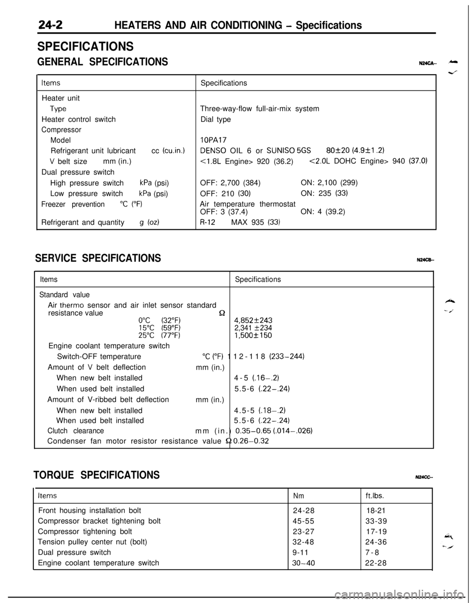
SPECIFICATIONS
GENERAL SPECIFICATIONSN24cA- -
ItemsSpecifications
Heater unit
TypeThree-way-flow full-air-mix system
Heater control switchDial type
Compressor
Model
lOPARefrigerant unit lubricantcc
(cu.in.1DENS0 OIL 6 or SUNISO 5GS80f20 (4.9&l .2)
V belt sizemm (in.)<1.8L Engine> 920 (36.2)<2.0L DOHC Engine> 940 (37.0)Dual pressure switch
High pressure switch
kPa (psi)OFF: 2,700 (384)ON: 2,100 (299)
Low pressure switch
kPa (psi)OFF: 210 (30)ON: 235 (33)
Freezer prevention“C (“F)Air temperature thermostat
OFF: 3 (37.4)ON: 4 (39.2)
Refrigerant and quantity
g bdR-12MAX 935 (33)
SERVICE SPECIFICATIONSN24CB.-
ItemsSpecifications
Standard valueAir
therm0 sensor and air inlet sensor standard
resistance value
n0°C (32°F)4,852f24315°C (59°F)2,341 f23425°C 177°F)1,500f 150Engine coolant temperature switch
Switch-OFF temperature
“C (“F) 112-118 (233-244)
Amount of
V belt deflection
mm (in.)
When new belt installed4-5
(.16-.2)When used belt installed5.5-6
(.22-.24)Amount of V-ribbed belt deflection
mm (in.)
When new belt installed4.5-5
(.18-.2)When used belt installed5.5-6
(.22-.24)
Clutch clearancemm (in.) 0.35-0.65 (.014-,026)
Condenser fan motor resistor resistance value
52 0.26-0.32
TORQUE SPECIFICATIONSN24CC-
ItemsNmft.lbs.Front housing installation bolt
24-2818-21
Compressor bracket tightening bolt
45-5533-39
Compressor tightening bolt
23-2717-19
Tension pulley center nut (bolt)
32-4824-36
Dual pressure switch
9-117-8
Engine coolant temperature switch
30-4022-28
k
- /.
Page 1167 of 1216
HEATERS AND AIR CONDITIONING - Service Adiustment Procedures 24-23
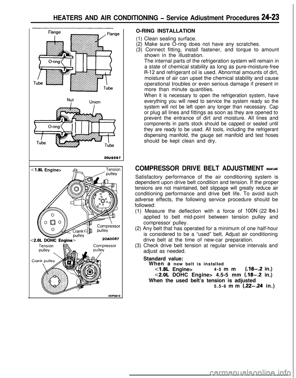
<
we2ouo2er
< 1.8L Engine>Tension/ wllevO-RING INSTALLATION
(1) Clean sealing surface.
(2) Make sure O-ring does not have any scratches.
(3) Connect fitting, install fastener, and torque to amount
shown in the illustration.
The internal parts of the refrigeration system will remain in
a state of chemical stability as long as pure-moisture-free
R-12 and refrigerant oil is used. Abnormal amounts of dirt,
moisture of air can upset the chemical stability and cause
operational troubles or even serious damage if present in
more than minute quantities.
When it is necessary to open the refrigeration system, have
everything you will need to service the system ready so the
system will not be left open any longer than necessary. Capor plug all lines and fittings as soon as they are opened to
prevent the entrance of dirt and moisture. All lines and
components in parts stock should be capped or sealed until
they are ready to be used. All tools, including the refrigerant
dispensing manifold, the gauge set manifold and test hosesshould be kept clean and dry.
COMPRESSOR DRIVE BELT ADJUSTMENT N24FJAESatisfactory performance of the air conditioning system is
dependent upon drive belt condition and tension. If the proper
tensions are not maintained, belt slippage will greatly reduce airconditioning performance and drive belt life. To avoid such
adverse effects, the following service procedure should be
followed:
(1) Measure the deflection with a force of
IOON (22 Ibs.)applied to belt mid-point between tension pulley and
compressor pulley.
(2) Any belt that has operated for a minimum of one half-hour
is considered to be a “used” belt. Adjust air conditioning
drive belt at the time of new-car preparation.
(3) Check drive belt tension at regular service intervals and
adjust as needed.
Standard value:
When a new belt is installed<1.8L Engine>4-5 mm
(.16-.2 in.)
<2.0L DOHC Engine> 4.5-5 mm (.18-.2 in.)
When the used belt’s tension is adjusted
5.5-6 mm
(.22-.24 in.)
Page 1168 of 1216
24-24 HEATERS AND AIR CONDITIONING - Service Adjustment Procedures
COMPRESSOR NOISENUFIABWhen investigating an air conditioning related noise, you must
first know the conditions when the noise occurs. These
conditions are: weather, vehicle speed, in gear or neutral,
engine temperature or any other special conditions.
Noises that develop during air conditioning operation can oftenbe misleading. For example: what sounds like a failed front
bearing or connecting rod, may be caused by loose bolts, nuts,mounting brackets, or a loose clutch assembly. Verify acces-
sory drive belt tension (power steering, or alternator).
Improper accessory drive belt tension can cause a misleading
noise when the compressor is engaged and little or no noise
when the compressor is disengaged.
Drive belts are speed sensitive. That is, at different engine
speeds, and depending upon belt tension, belts can develop
unusual noises that are often mistaken for mechanical prob-
lems within the compressor.
Adjustment Procedures
(1) Select a quiet area for testing. Duplicate conditions as
much as possible. Switch compressor on and off several
times to clearly identify compressor noise.
To duplicate high ambient conditions (high head pressure),restrict air flow through condenser. Install manifold gauge
set to make sure discharge pressure doesn’t exceed 2,070
kPa (300 psi).
(2) Tighten all compressor mounting bolts, clutch mounting
bolt, and compressor drive belt. Check to assure clutch coilis tight (no rotation or wobble).
(3) Check refrigerant hoses for rubbing or interference that cancause unusual noises.
(4) Check refrigerant charge (See “Charging the System”).
(5) Recheck compressor noise as in Step 1.
(6) If noise still exists, loosen compressor mounting bolts and
retorque. Repeat Step 1.
(7) If noise continues, replace compressor and repeat Step 1.
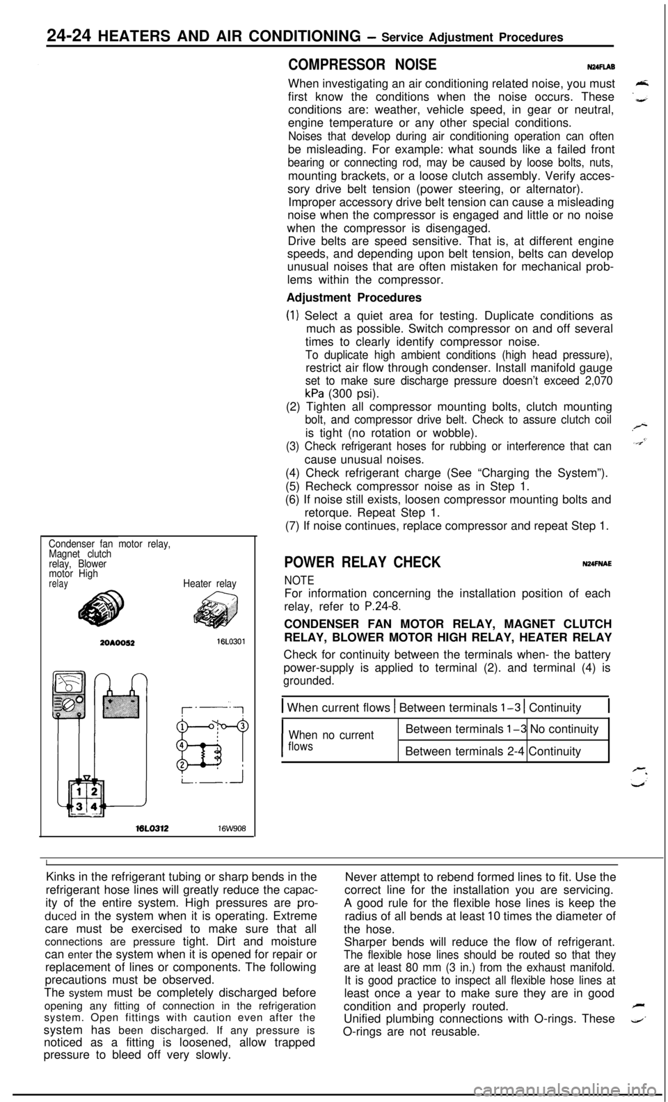
Condenser fan motor relay,
Magnet clutch
relay, Blower
motor High
relayHeater relayML0312
16W908
POWER RELAY CHECKNUFNAE
NOTEFor information concerning the installation position of each
relay, refer to
P.24-8.CONDENSER FAN MOTOR RELAY, MAGNET CLUTCH
RELAY, BLOWER MOTOR HIGH RELAY, HEATER RELAY
Check for continuity between the terminals when- the battery
power-supply is applied to terminal (2). and terminal (4) is
grounded.
1 When current flows 1 Between terminals l-3 1 Continuity1
I
When no currentBetween terminals l-3 No continuity
flowsBetween terminals 2-4 Continuity
IKinks in the refrigerant tubing or sharp bends in the
Never attempt to rebend formed lines to fit. Use the
refrigerant hose lines will greatly reduce the
capac-correct line for the installation you are servicing.
ity of the entire system. High pressures are
pro-A good rule for the flexible hose lines is keep the
duced in the system when it is operating. Extreme
radius of all bends at least 10 times the diameter of
care must be exercised to make sure that all
the hose.
connections are pressure tight. Dirt and moisture
Sharper bends will reduce the flow of refrigerant.
can enter the system when it is opened for repair or
The flexible hose lines should be routed so that theyreplacement of lines or components. The following
are at least 80 mm (3 in.) from the exhaust manifold.precautions must be observed.
It is good practice to inspect all flexible hose lines atThe system must be completely discharged before
least once a year to make sure they are in good
opening any fitting of connection in the refrigeration
condition and properly routed.
Fsystem. Open fittings with caution even after the
Unified plumbing connections with O-rings. These
4’system has been discharged. If any pressure is
noticed as a fitting is loosened, allow trappedO-rings are not reusable.
pressure to bleed off very slowly.
Page 1187 of 1216
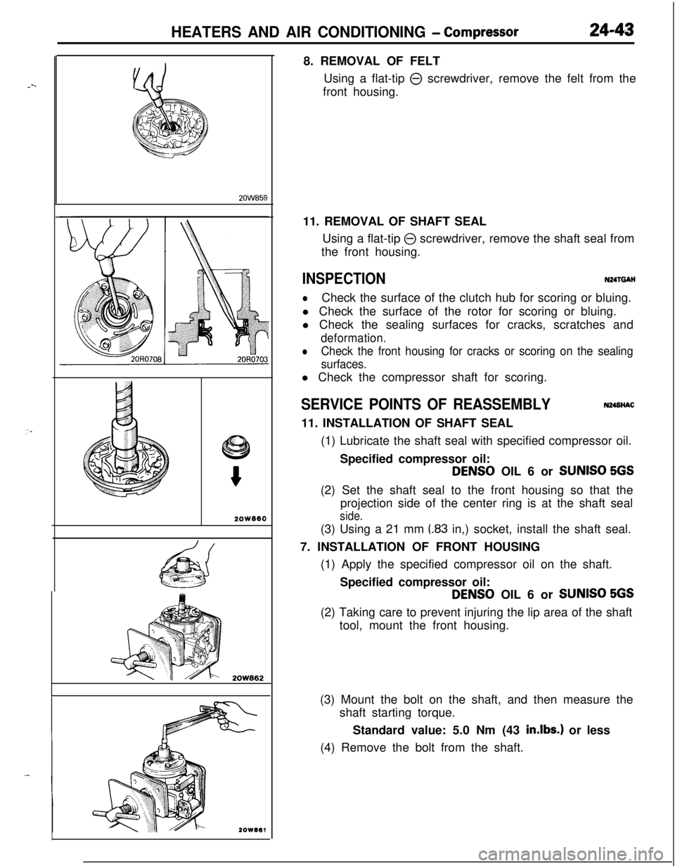
HEATERS AND AIR CONDITIONING - Compiessor24-43
2OW660
2OW8628. REMOVAL OF FELT
Using a flat-tip
0 screwdriver, remove the felt from the
front housing.
11. REMOVAL OF SHAFT SEAL
Using a flat-tip
0 screwdriver, remove the shaft seal from
the front housing.
INSPECTIONN24TGAH
lCheck the surface of the clutch hub for scoring or bluing.
l Check the surface of the rotor for scoring or bluing.
l Check the sealing surfaces for cracks, scratches and
deformation.
lCheck the front housing for cracks or scoring on the sealing
surfaces.l Check the compressor shaft for scoring.
SERVICE POINTS OF REASSEMBLYN24StiAC11. INSTALLATION OF SHAFT SEAL
(1) Lubricate the shaft seal with specified compressor oil.
Specified compressor oil:
DENS0 OIL 6 or SUNISO 5GS(2) Set the shaft seal to the front housing so that the
projection side of the center ring is at the shaft seal
side.(3) Using a 21 mm
(.83 in,) socket, install the shaft seal.
7. INSTALLATION OF FRONT HOUSING
(1) Apply the specified compressor oil on the shaft.
Specified compressor oil:
DENS0 OIL 6 or SUNISO 5GS(2) Taking care to prevent injuring the lip area of the shaft
tool, mount the front housing.
(3) Mount the bolt on the shaft, and then measure the
shaft starting torque.
Standard value: 5.0 Nm (43
in.lbs.) or less
(4) Remove the bolt from the shaft.
Page 1197 of 1216
.^
EMISSION CONTROL
SYSTEMS
CONTENTSN25AA-
CATALYTICCONVERTER...............................20CRANKCASE EMISSION CONTROL
SYSTEM...........................................................7Components Location
...................................7Crankcase Ventilation System
Inspection......................................................8Positive Crankcase Ventilation Valve
...........8EVAPORATIVE EMISSION CONTROL
SYSTEM...........................................................9
AirConditionerSwitch.................................14Air Flow Sensor, Engine Coolant
Temperature Sensor and Intake Air
Temperature Sensor
.....................................14
Canister.........................................................14Components Location
...................................9
FuelFillerCapInspection............................14Overfill Limiter (Two-way Valve)
..................14
PurgeControlSolenoidValve......................13Purge Control
SystemInspection................11
PurgeControlValve
SYSTEM...........................................................15Air-fuel Ratio Control (MPI) System
............20Components Location
...................................15EGR Control Solenoid Valve
.................................................19
EGR
SystemInspection...............................17EGR Temperature Sensor
......19
EGR Valve.....................................................18
Therm0 Valve
SPECIFICATIONS.............................................2General Specifications
..................................2
Sealant..........................................................2Service Specifications
...................................2
TorqueSpecifications...................................2
TROUBLESHOOTING......................................3
VACUUMHOSES...........................................4
VacuumHosesRouting...............................4