lock MITSUBISHI ECLIPSE 1991 Service Manual
[x] Cancel search | Manufacturer: MITSUBISHI, Model Year: 1991, Model line: ECLIPSE, Model: MITSUBISHI ECLIPSE 1991Pages: 1216, PDF Size: 67.42 MB
Page 786 of 1216
MANUAL TRANSAXLE
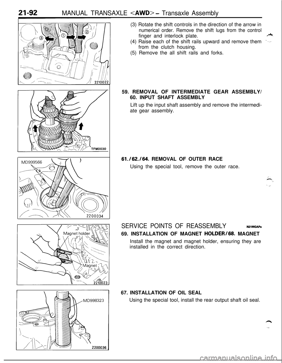
numerical order. Remove the shift lugs from the controlfinger and interlock plate.
(4) Raise each of the shift rails upward and remove them
from the clutch housing.
(5) Remove the all shift rails and forks.
59. REMOVAL OF INTERMEDIATE GEAR ASSEMBLY/
60. INPUT SHAFT ASSEMBLY
Lift up the input shaft assembly and remove the intermedi-
ate gear assembly.
61./62./64. REMOVAL OF OUTER RACE
Using the special tool, remove the outer race.
SERVICE POINTS OF REASSEMBLYN21MGAPa69. INSTALLATION OF MAGNET HOLDER/68. MAGNET
Install the magnet and magnet holder, ensuring they are
installed in the correct direction.
67. INSTALLATION OF OIL SEAL
Using the special tool, install the rear output shaft oil seal.
Page 788 of 1216
21-94MANUAL TRANSAXLE
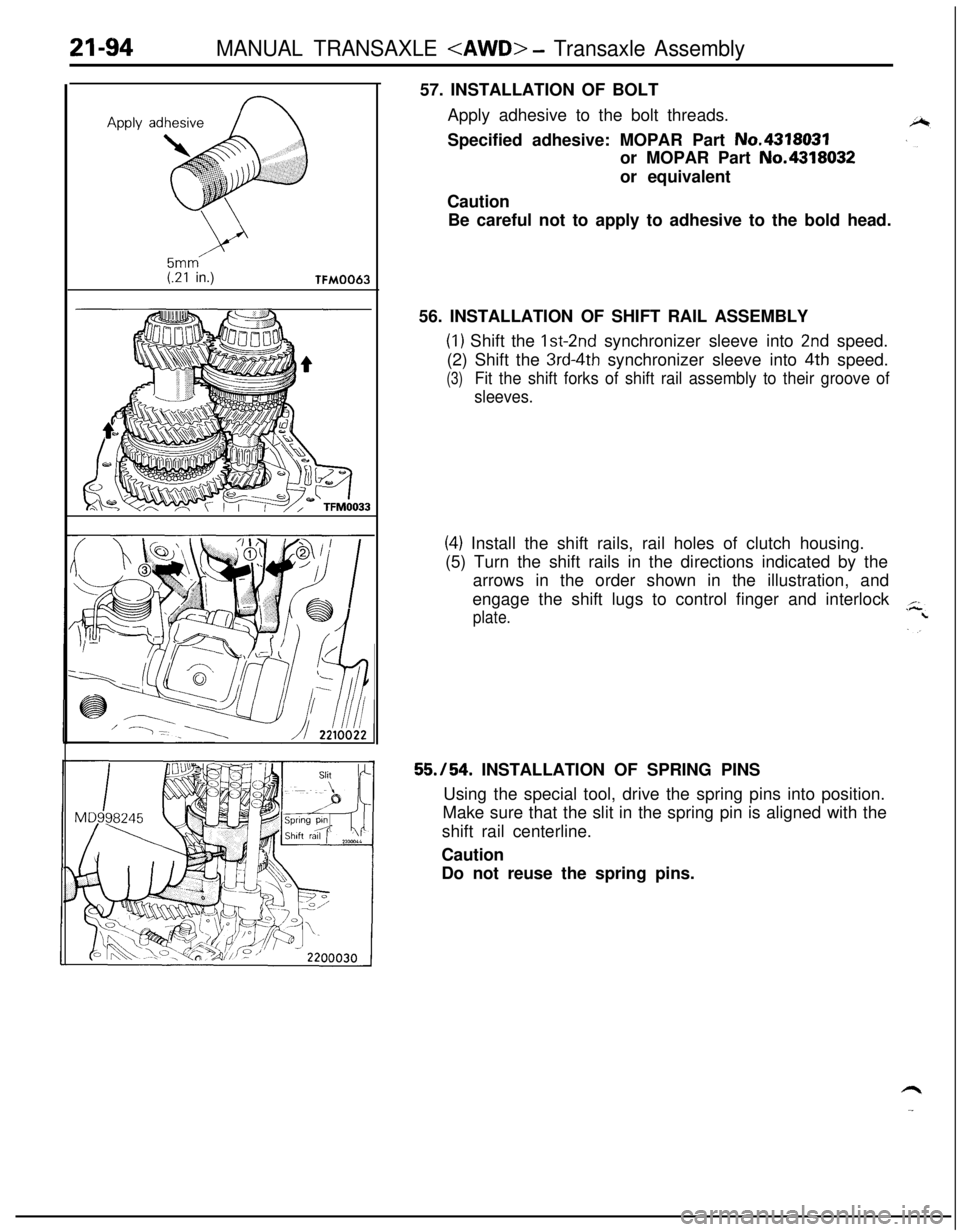
5mm(.21 in.)TFM006357. INSTALLATION OF BOLT
Apply adhesive to the bolt threads.
Specified adhesive: MOPAR Part No.4318031
or MOPAR Part No.4318032
or equivalent
Caution
Be careful not to apply to adhesive to the bold head.
56. INSTALLATION OF SHIFT RAIL ASSEMBLY
(1) Shift the Ist-2nd synchronizer sleeve into 2nd speed.
(2) Shift the
3rd-4th synchronizer sleeve into 4th speed.
(3)Fit the shift forks of shift rail assembly to their groove of
sleeves.
(4) Install the shift rails, rail holes of clutch housing.
(5) Turn the shift rails in the directions indicated by the
arrows in the order shown in the illustration, and
engage the shift lugs to control finger and interlock
plate.
55./54. INSTALLATION OF SPRING PINS
Using the special tool, drive the spring pins into position.
Make sure that the slit in the spring pin is aligned with the
shift rail centerline.
Caution
Do not reuse the spring pins.
Page 792 of 1216
21-98MANUAL TRANSAXLE
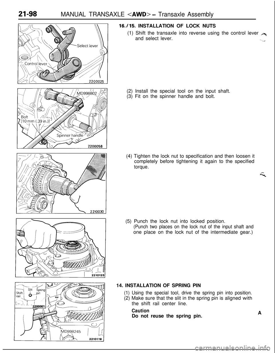
16.115. INSTALLATION OF LOCK NUTS
(1) Shift the transaxle into reverse using the control lever
,+and select lever.
.,./(2) Install the special tool on the input shaft.
(3) Fit on the spinner handle and bolt.
(4) Tighten the lock nut to specification and then loosen it
completely before tightening it again to the specified
torque.
i;(5) Punch the lock nut into locked position.
(Punch two places on the lock nut of the input shaft andone place on the lock nut of the intermediate gear.)
14. INSTALLATION OF SPRING PIN
(1) Using the special tool, drive the spring pin into position.(2) Make sure that the slit in the spring pin is aligned with
the shift rail center line.
CautionDo not reuse the spring pin.A
Page 800 of 1216
21-106MANUAL TRANSAXLE
FRONT DIFFERENTIAL
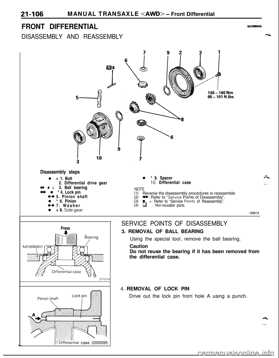
DISASSEMBLY AND REASSEMBLY
NZIMMAG
i;&
Disassembly stepsl + 1. Bolt
2. Differential drive gear
** l +3. Ball bearing+* l * 4. Lock pinI)+ 5. Pinion shaft
l * 6. Pinion
I)+ 7. Washer
l + 8. Sidegear
95-lOl ft.lbs.l * 9. Spacer10. Differential case
NOTE(I)Reverse the disassembly procedures to reassemble(2)C*: Refer to “Service Points of Disassembly”.(3)l +: Refer to “Service Points of Reassembly”.(4)q : Non-reusable parts.
:&
-_-
160015
Press
teal case 2200095
SERVICE POINTS OF DISASSEMBLY3. REMOVAL OF BALL BEARING
Using the special tool, remove the ball bearing.
Caution
Do not reuse the bearing if it has been removed from
the differential case.
4. REMOVAL OF LOCK PIN
Drive out the lock pin from hole A using a punch.
Page 801 of 1216
MANUAL TRANSAXLE
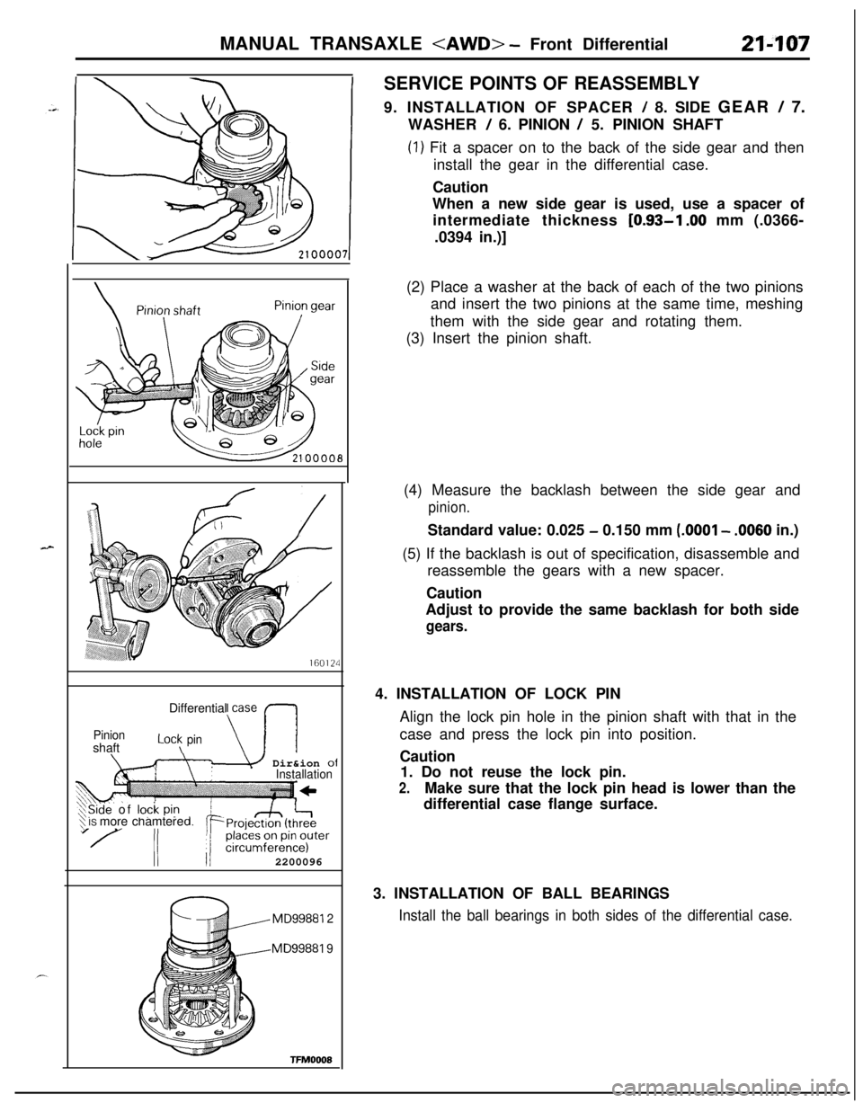
9. INSTALLATION OF SPACER
! 8. SIDE GEAR / 7.
WASHER
/ 6. PINION / 5. PINION SHAFT
(1) Fit a spacer on to the back of the side gear and then
install the gear in the differential case.
Caution
When a new side gear is used, use a spacer of
intermediate thickness
[0.93-l .OO mm (.0366-
.0394 in.)]
160124Differential case
PinionshaftLot\ pin\-I\m Dir&ion ofInstallation
‘$ IS more chamtereXSide of lock pi? d,
II II2200096
MD99881 2
MD99881 9
TFMOOOE(2) Place a washer at the back of each of the two pinions
and insert the two pinions at the same time, meshing
them with the side gear and rotating them.
(3) Insert the pinion shaft.
(4) Measure the backlash between the side gear and
pinion.Standard value: 0.025
- 0.150 mm (.OOOl - .0060 in.)
(5) If the backlash is out of specification, disassemble and
reassemble the gears with a new spacer.
Caution
Adjust to provide the same backlash for both side
gears.4. INSTALLATION OF LOCK PIN
Align the lock pin hole in the pinion shaft with that in the
case and press the lock pin into position.
Caution
1. Do not reuse the lock pin.
2.Make sure that the lock pin head is lower than the
differential case flange surface.
3. INSTALLATION OF BALL BEARINGS
Install the ball bearings in both sides of the differential case.
Page 803 of 1216
,-’ DISASSEMBLY AND REASSEMBLY
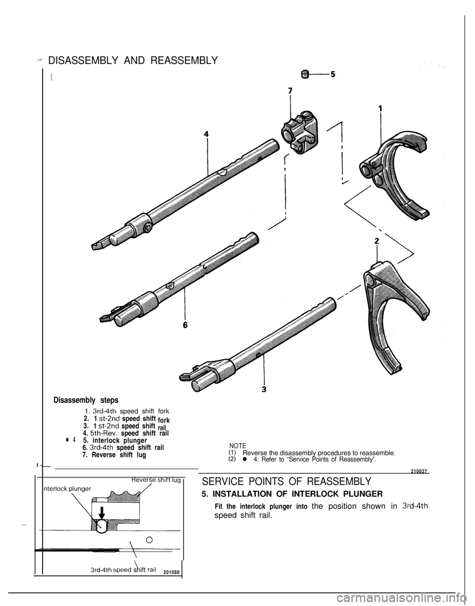
II-
Disassembly steps1.
3rd-4th speed shift fork
2.
1
st-2nd speed shift
fork
3.
1 st-2nd speed shiftrail4. 5th-Rev. speed shift raill 45.
interlock plunger
6.
3rd-4th speed shift railNOTE7. Reverse shift lug(1)Reverse the disassembly procedures to reassemble.(2)l 4: Refer to “Service Points of Reassembly”.-
\3rd-4th speed shift rail201088210027
SERVICE POINTS OF REASSEMBLY5. INSTALLATION OF INTERLOCK PLUNGER
Fit the interlock plunger into the position shown in
3rd-4thspeed shift rail.
Page 815 of 1216
MANUAL TRANSAXLE
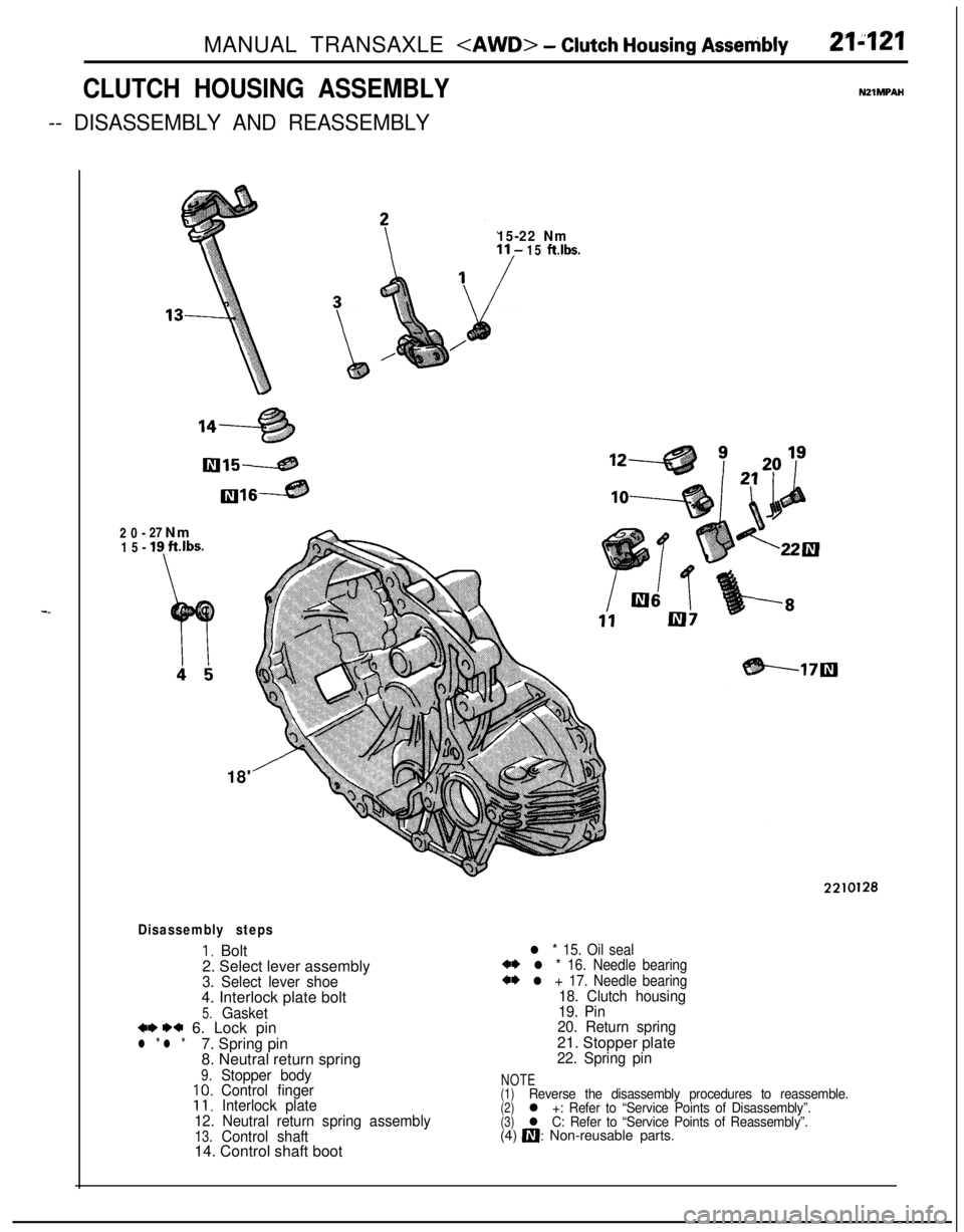
CLUTCH HOUSING ASSEMBLY
-- DISASSEMBLY AND REASSEMBLY
NZlMPAH
-20-27 Nm
15-
19 ft.lbs.
15-22 Nm15 ft.lbs.18'
Disassembly steps
I, Bolt
2. Select lever assembly
3. Select lever shoe4. Interlock plate bolt
5.Gasket+* WC 6. Lock pinl * l *7. Spring pin
8. Neutral return spring
9.Stopper body10.Control finger11,Interlock plate
12. Neutral return spring assembly
13.Control shaft14. Control shaft boot
2210128
l * 15. Oil seal*I) l * 16. Needle bearing
a* l + 17. Needle bearing18. Clutch housing
19. Pin
20. Return spring21. Stopper plate
22. Spring pin
NOTE(1)Reverse the disassembly procedures to reassemble.(2)l +: Refer to “Service Points of Disassembly”.(3)l C: Refer to “Service Points of Reassembly”.(4) a: Non-reusable parts.
Page 816 of 1216
21-122MANUAL TRANSAXLE
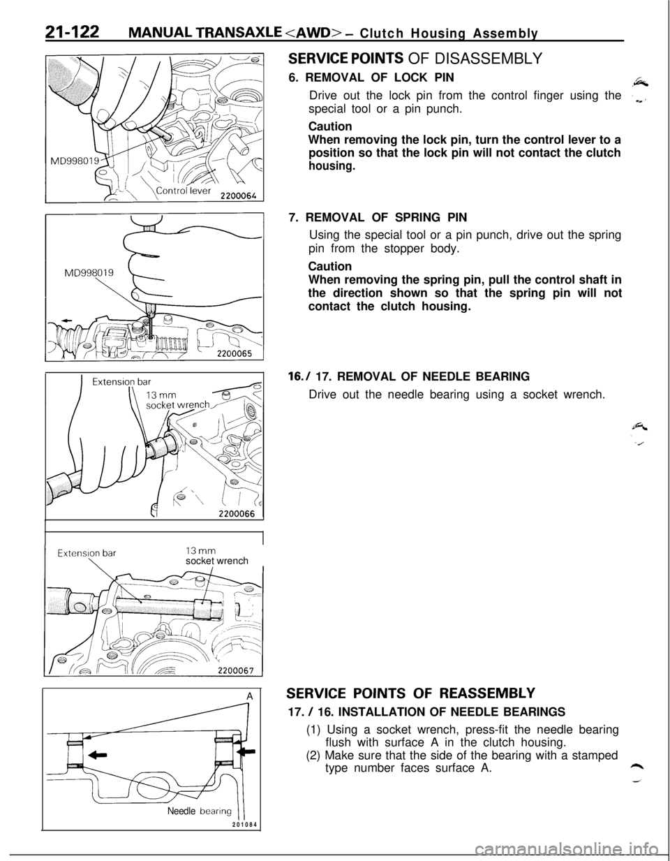
SERVICE POINTS OF DISASSEMBLY
6. REMOVAL OF LOCK PIN
Drive out the lock pin from the control finger using the
special tool or a pin punch.
Caution
When removing the lock pin, turn the control lever to a
position so that the lock pin will not contact the clutch
housing.13mm
socket wrench
A
Needle bearingII2010847. REMOVAL OF SPRING PIN
Using the special tool or a pin punch, drive out the spring
pin from the stopper body.
Caution
When removing the spring pin, pull the control shaft in
the direction shown so that the spring pin will not
contact the clutch housing.
16.7 17. REMOVAL OF NEEDLE BEARING
Drive out the needle bearing using a socket wrench.
SERVICE POINTS OF REASSEMBLY17.
/ 16. INSTALLATION OF NEEDLE BEARINGS
(1) Using a socket wrench, press-fit the needle bearing
flush with surface A in the clutch housing.
(2) Make sure that the side of the bearing with a stamped
type number faces surface A.
Page 817 of 1216
MANUAL TRANSAXLE
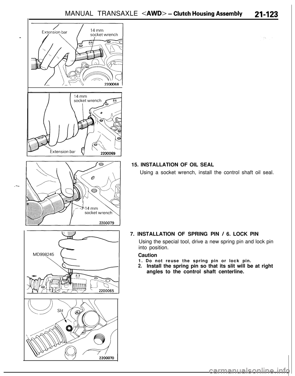
Using a socket wrench, install the control shaft oil seal.
7. INSTALLATION OF SPRING PIN
/ 6. LOCK PIN
Using the special tool, drive a new spring pin and lock pin
into position.
Caution
1. Do not reuse the spring pin or lock pin.
2.Install the spring pin so that its slit will be at right
angles to the control shaft centerline.
Page 825 of 1216
MANUAL TRANSAXLE
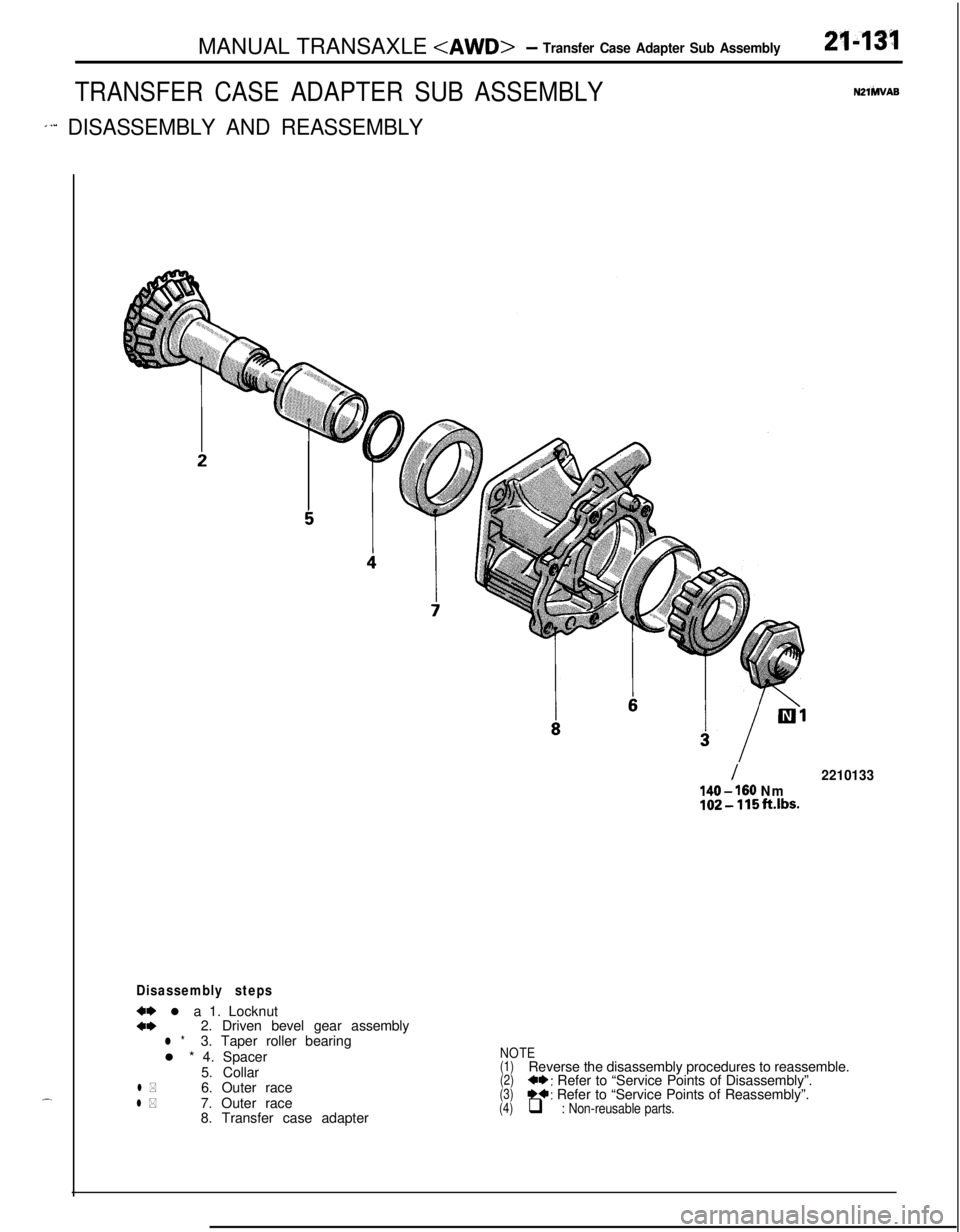
TRANSFER CASE ADAPTER SUB ASSEMBLY
1’” DISASSEMBLY AND REASSEMBLY
2143’1
N2lhlVAS.-
Disassembly steps
w l a 1. Locknuta*2. Driven bevel gear assemblyl *3. Taper roller bearing
l * 4. Spacer
5. Collar
l *6. Outer racel *7. Outer race
8. Transfer case adapter
I2210133
140 - 160 Nm102-115ft.lbs.
NOTE(1)Reverse the disassembly procedures to reassemble.(2)+*: Refer to “Service Points of Disassembly”.(3)*+: Refer to “Service Points of Reassembly”.(4)q : Non-reusable parts.