engine MITSUBISHI ECLIPSE 1991 Service Manual
[x] Cancel search | Manufacturer: MITSUBISHI, Model Year: 1991, Model line: ECLIPSE, Model: MITSUBISHI ECLIPSE 1991Pages: 1216, PDF Size: 67.42 MB
Page 890 of 1216
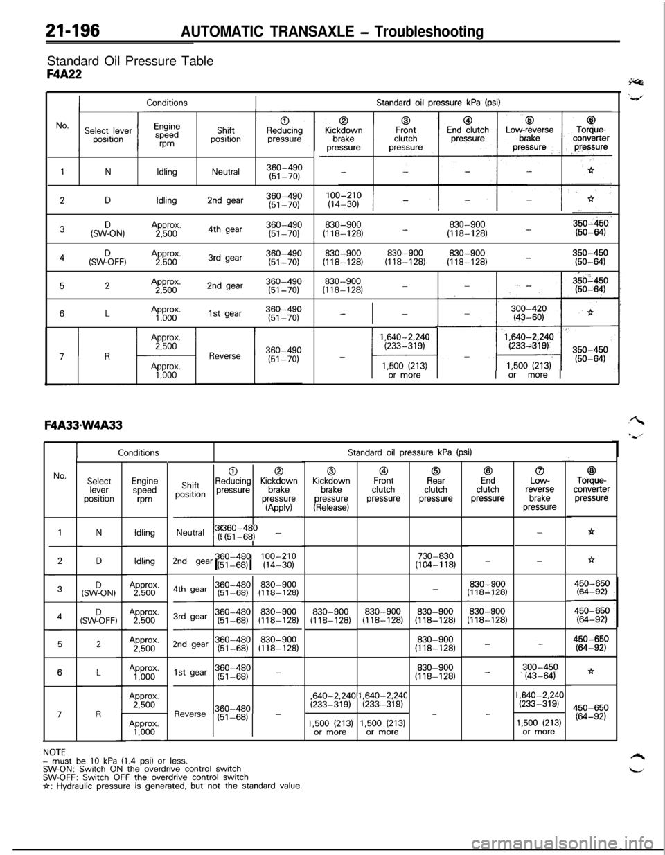
21-196AUTOMATIC TRANSAXLE - TroubleshootingStandard Oil Pressure Table
F4A22
Standard oil pressure kPa (psi)Conditions
1NIdlingNeutral360-490(51-70)
2DIdling2nd gear360-490(51-70)
3&ON,Approx.360-4902,5004th gear(51-70)830-900830-900(118-128) -(118-128) -
830-900830-900830-900350-450(118-128)(118-128)(118-128) -(50-6434(SWF)oFF, ,A2pp5boox.3rd gear360-490(51-70)
52Approx.2nd gear360-4902,500(51-70)830-900(118-128)-
6LAp”60”.1st gear360-490(51-70)-I-
1,640-2.240(233-319)-
l-41,500 (213)or more1 or more I
TStandard oil pressure kPa (psi)
0Kickdown
brakepressure
(Release)
@IFrontclutchpressure
0Rearclutchpressure
c3Endclutchpressure
0Low-reverse
brakepressure
00ShiftpositionReducing KickM;vnpressurepressure
-l---l
(APPM
Neutral !r$I$$ -
c3Torque-converter
pressure
h
No.SelectleverpositionEnginespeed
m
Idling
IdlingApprox.2,500Approx.
1,000Approx.2,500
N-
-
LI
*D730-830(104-118)2nd gear (51-68)I I360-480 100-210(14-30)-
830-900(118-128)(SWFON,-
830-900(118-128)830-900(118-128)4SW%FF:830-900(118-128)830-900(118-128)
2450-650(64-92)
*
450-650(64-92)
830-900(118-128)
830-900(118-128)
-
-6,640-2.24C
(233-319),640-2.24C(233-319)I ,640-2.24C(233-319)III
17-
1.500 (213)or more1,500 (213)or more1,500 (213)or more
NOTEmust be 10 kPa (1.4 psi) or less.SW-ON: Switch ON the overdrive control switchSW-OFF: Switch OFF the overdrive control switchI+: Hydraulic pressure is generated, but not the standard value.
Page 896 of 1216
21-202AUTOMATIC TRANSAXLE - Troubleshooting
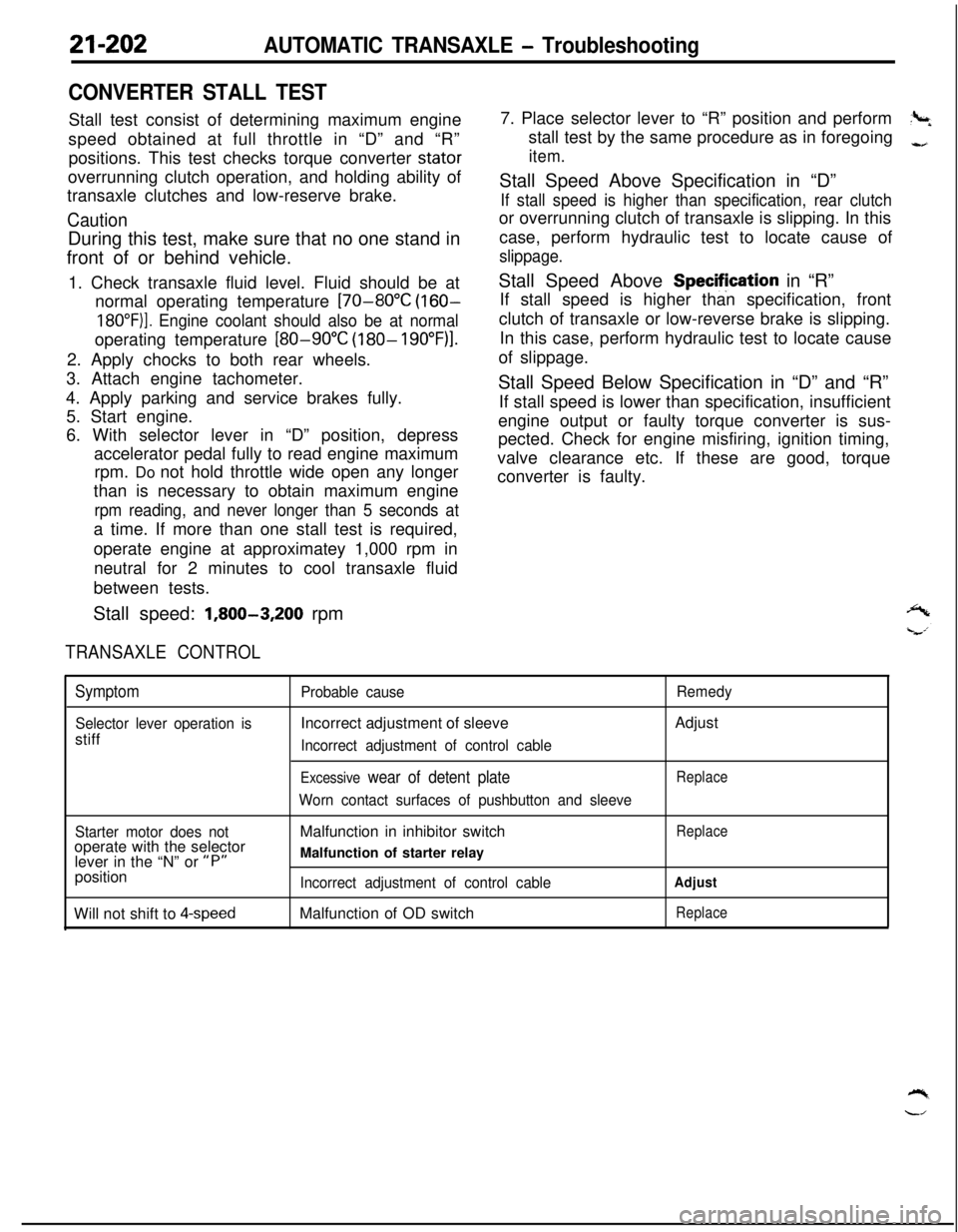
CONVERTER STALL TESTStall test consist of determining maximum engine
speed obtained at full throttle in “D” and “R”
positions. This test checks torque converter stator
overrunning clutch operation, and holding ability of
transaxle clutches and low-reserve brake.
CautionDuring this test, make sure that no one stand in
front of or behind vehicle.
1. Check transaxle fluid level. Fluid should be at
normal operating temperature
[70-80°C (160-
18O”F)]. Engine coolant should also be at normaloperating temperature
[80-90°C (180- 19O”F)l.2. Apply chocks to both rear wheels.
3. Attach engine tachometer.
4. Apply parking and service brakes fully.
5. Start engine.
6. With selector lever in “D” position, depress
accelerator pedal fully to read engine maximum
rpm. Do not hold throttle wide open any longer
than is necessary to obtain maximum engine
rpm reading, and never longer than 5 seconds ata time. If more than one stall test is required,
operate engine at approximatey 1,000 rpm in
neutral for 2 minutes to cool transaxle fluid
between tests.
Stall speed:
1,800-3,200 rpm
TRANSAXLE CONTROL7. Place selector lever to “R” position and perform
?+stall test by the same procedure as in foregoing
-,
item.Stall Speed Above Specification in “D”
If stall speed is higher than specification, rear clutchor overrunning clutch of transaxle is slipping. In this
case, perform hydraulic test to locate cause of
slippage.Stall Speed Above Specifjcation in “R”
If stall speed is higher than specification, front
clutch of transaxle or low-reverse brake is slipping.
In this case, perform hydraulic test to locate cause
of slippage.
Stall Speed Below Specification in “D” and “R”
If stall speed is lower than specification, insufficient
engine output or faulty torque converter is sus-
pected. Check for engine misfiring, ignition timing,
valve clearance etc. If these are good, torque
converter is faulty.
Symptom
Selector lever operation isstiff
Probable causeIncorrect adjustment of sleeve
Incorrect adjustment of control cable
Excessive wear of detent plate
Worn contact surfaces of pushbutton and sleeveRemedyAdjust
Replace
Starter motor does notoperate with the selector
lever in the “N” or
“P”position
Will not shift to
4-speedMalfunction in inhibitor switch
Malfunction of starter relay
Incorrect adjustment of control cableMalfunction of OD switch
Replace
Adjust
Replace
Page 899 of 1216
AUTOMATIC TRANSAXLE - Troubleshooting21-205
AIR CONDITIONER
CONTROL UNITIGNI
CRCFILTER
B-11
ON+OFF:2700kP.%(384Psl)OFF+ON:
$;X;kERATOR
SWITCH
WITH
WITHOUT,$J;$JR~;UISE 1AUTO-CRUISE. CONTROL
SELFJ-DIAGNOSIS
CONNECTOR
TIO1
/-1. 8LENGINE
3J
I
IL.&.j IUK1
mB
x 1
mm
CLCL
--
‘----_06
Pz
1_----
t
29I
POWE
TRANSTOR
c-30
FRONT SIDE
p&a-q
E%ERSE
p!!iQqI-----
101
NON-TURBC
/ 0
2_----II
A
-----02
9
I.----,
IL-B
GtD G:DGB“tD----1
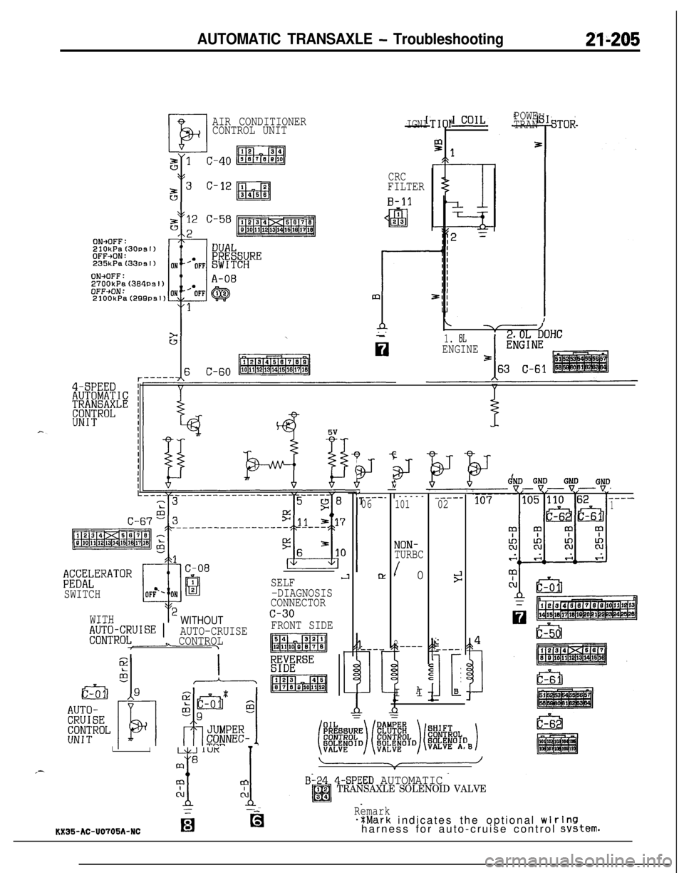
B-24 4-SPEED AUTOMATICTRANSAXLE SOLENOID VALVE
Remark*%Mark indicates the optional wlrlnsharness for auto-cruise control system.KX35-AC-U0705A-NCfg
Page 900 of 1216
21-206AUTOMATIC TRANSAXLE - Troubleshooting
r-------1.8L ENGINEirI I
---_-____-_--
2.0L DOHC ENGINE
C-66
aB1 c-47 l ’
J/B
\/2 c-50
2-i
,7
C-67
ID;ESWITCH
B-05 q ’
I
,21
i-I+
*
-id-
*
-
i-ET
C--
.--C
1--
-
A-37
I@JJ
NON-TURBO
I,1,.1 $~#~OWN
SWITCH
,
A-38
TURBO-IIBI--------
r
kxrnc
--.--
c!--
31
?--
.--
3
I‘--
:
m
Ii
5- 59 D-06
h
I
I
I
COMBINATION i1
METER
D-05 m
-u-uu-u
PULSEGENERATOR
A-51
,4/s&q4 c-49 12
J-r
EDa411 12“pcu
Page 901 of 1216
AUTOMATIC TRANSAXLE - Troubleshooting21-207
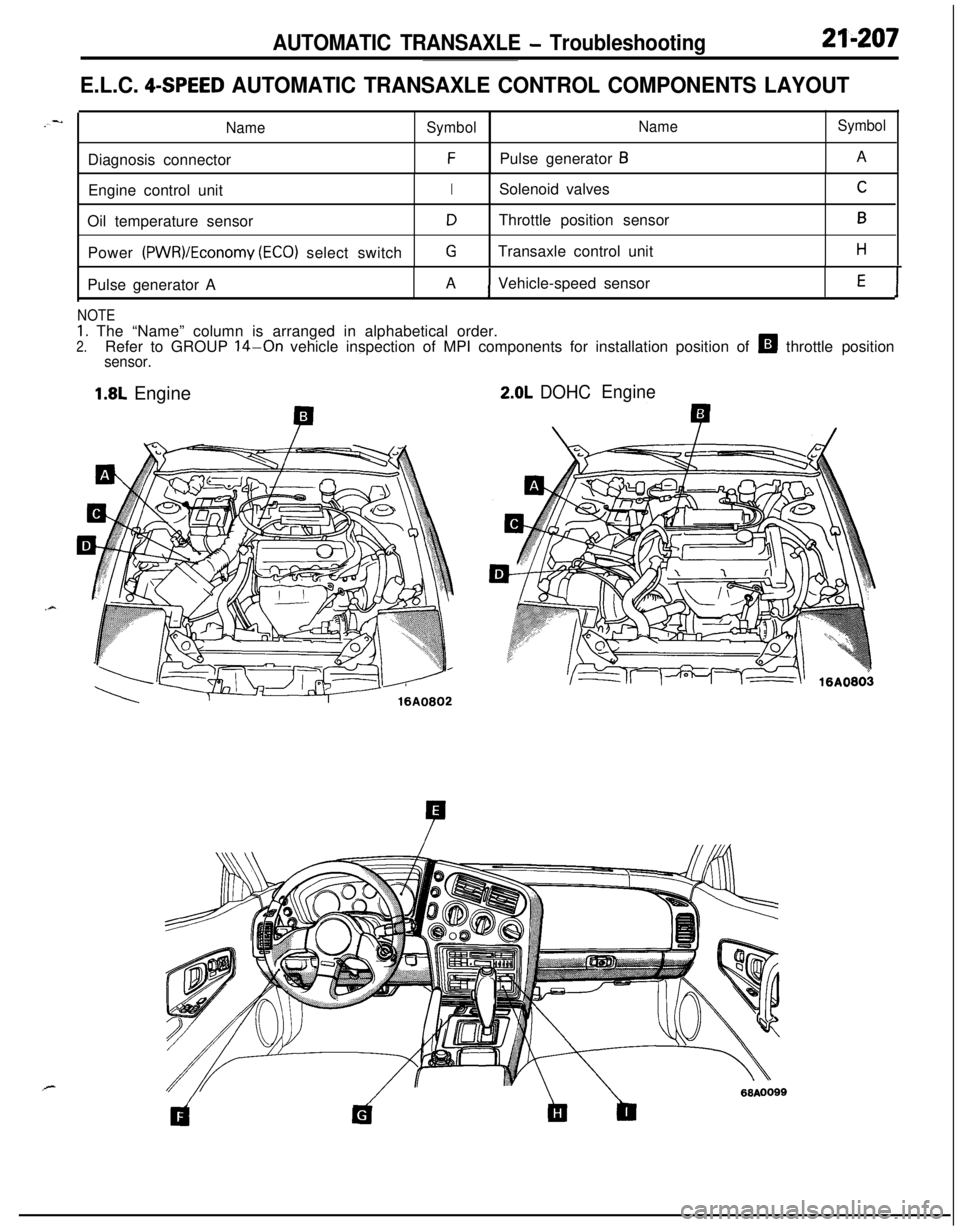
E.L.C. 4-SPEED AUTOMATIC TRANSAXLE CONTROL COMPONENTS LAYOUT
NameSymbolNameSymbolDiagnosis connector
FPulse generator BA
Engine control unit
ISolenoid valvesCOil temperature sensor
DThrottle position sensorBPower
(PWR)/Economy (ECO) select switchGTransaxle control unitHPulse generator AAVehicle-speed sensor
E1
NOTE
1. The “Name” column is arranged in alphabetical order.2.Refer to GROUP 14-On vehicle inspection of MPI components for installation position of H throttle positionsensor.
1.8L Engine2.0L DOHCEngine
Page 904 of 1216
21-210AUTOMATIC TRANSAXLE - Service Adjustment Procedures
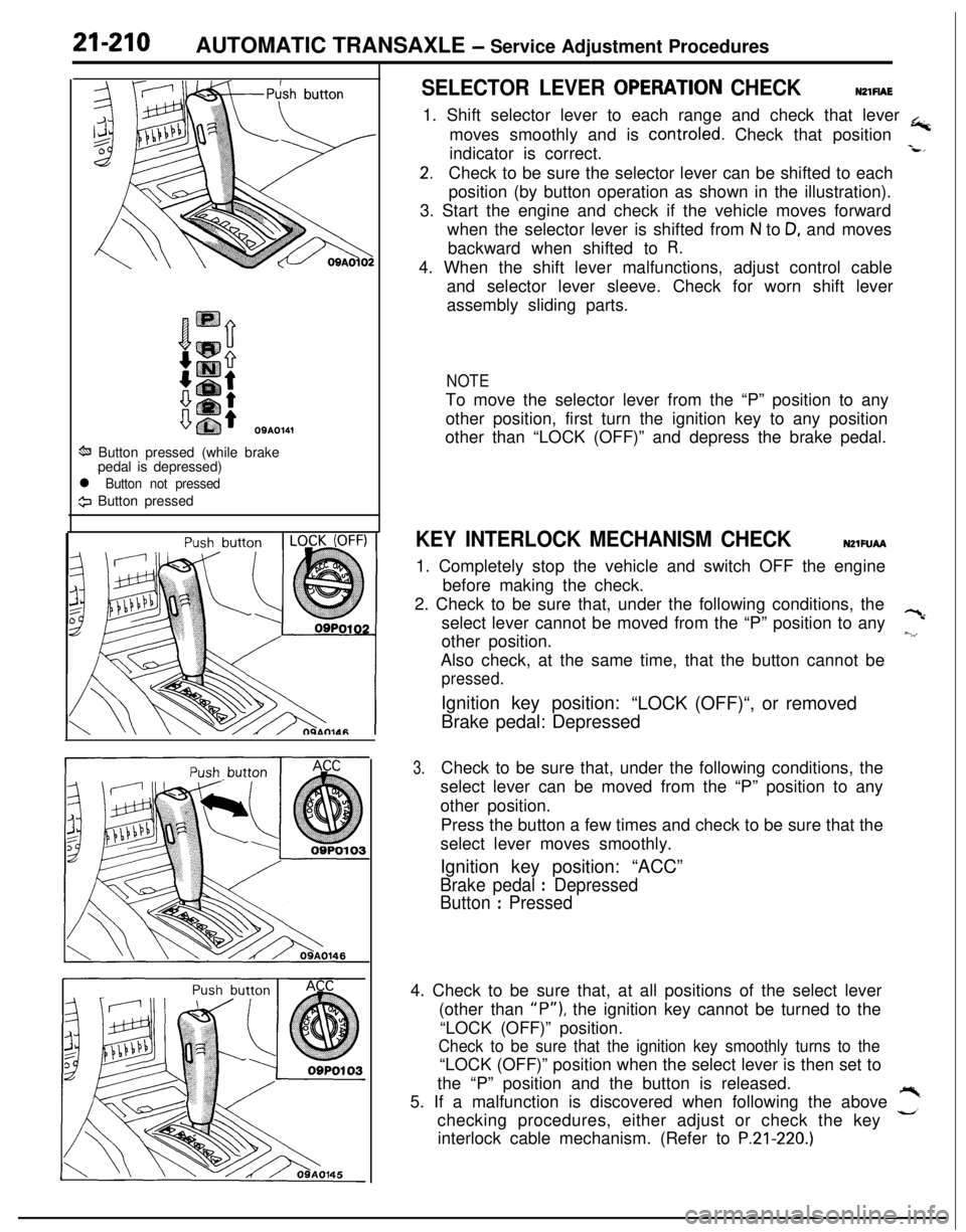
OSA0141
ti Button pressed (while brake
pedal is depressed)
l Button not pressed
9 Button pressed
SELECTOR LEVER OPERATlON CHECKNZlFlAE1. Shift selector lever to each range and check that lever
+moves smoothly and is controled. Check that position
indicator is correct.
-L*
2.Check to be sure the selector lever can be shifted to each
position (by button operation as shown in the illustration).
3. Start the engine and check if the vehicle moves forward
when the selector lever is shifted from
N to D, and moves
backward when shifted to
R.4. When the shift lever malfunctions, adjust control cable
and selector lever sleeve. Check for worn shift lever
assembly sliding parts.
NOTETo move the selector lever from the “P” position to any
other position, first turn the ignition key to any position
other than “LOCK (OFF)” and depress the brake pedal.
KEY INTERLOCK MECHANISM CHECKNZlFUAA1. Completely stop the vehicle and switch OFF the engine
before making the check.
2. Check to be sure that, under the following conditions, the
select lever cannot be moved from the “P” position to any
?cother position.
~.‘,Also check, at the same time, that the button cannot be
pressed.Ignition key position:
“LOCK (OFF)“, or removed
Brake pedal: Depressed
3.Check to be sure that, under the following conditions, the
select lever can be moved from the “P” position to any
other position.
Press the button a few times and check to be sure that the
select lever moves smoothly.
Ignition key position: “ACC”
Brake pedal : Depressed
Button
: Pressed4. Check to be sure that, at all positions of the select lever
(other than
“P”), the ignition key cannot be turned to the
“LOCK (OFF)” position.
Check to be sure that the ignition key smoothly turns to the“LOCK (OFF)” position when the select lever is then set to
the “P” position and the button is released.
5. If a malfunction is discovered when following the above
,”checking procedures, either adjust or check the key
interlock cable mechanism. (Refer to
P.21-220.)
Page 919 of 1216
AUTOMATIC TRANSAXLE - Transaxle Assembly
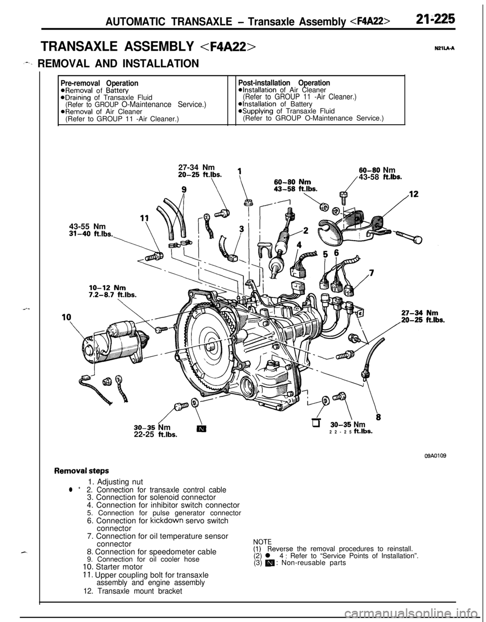
TRANSAXLE ASSEMBLY
,--. REMOVAL AND INSTALLATION
Pre-removal OperationPost-installation Operation@Removal of Battew@Installation of Air CleaneraDraining of Transaxle Fluid(Refer to GROUP 11 -Air Cleaner.)(Refer to GROUP O-Maintenance Service.)@Installation of BatteryaRemoval of Air Cleaner*Supplying of Transaxle Fluid
(Refer to GROUP 11 -Air Cleaner.)(Refer to GROUP O-Maintenance Service.)
27-34 Nm20-25
ftlbs.
1143-55 Nm31-40
ft.lbs.-\60-80
flrn60-80 Nm/43-58 ft.lbs.
//\-LTT \.30-35 Nm
AIq 30-35 Nm22-25 klbs.22-25 ft.lbs.
09A0109
Removal steps1. Adjusting nut
l *2. Connection for transaxle control cable3. Connection for solenoid connector
4. Connection for inhibitor switch connector
5. Connection for pulse generator connector
6. Connection for kickdown servo switch
connector
7. Connection for oil temperature sensor
connector
8. Connection for speedometer cable
9. Connection for oil cooler hose
10. Starter motor
11. Upper coupling bolt for transaxleassembly and engine assembly
12. Transaxle mount bracket
$?everse the removal procedures to reinstall.
(2) l 4 : Refer to “Service Points of Installation”.
(3) m : Non-reusable parts
Page 920 of 1216
21-226AUTOMATIC TRANSAXLE - Transaxle Assembly
33-38
ftlbs.30-35 Nm
22-25
ftlbs.IO-12 Nm
7-9 ftlbs.
7-10 ft.lbs.
I18m
16
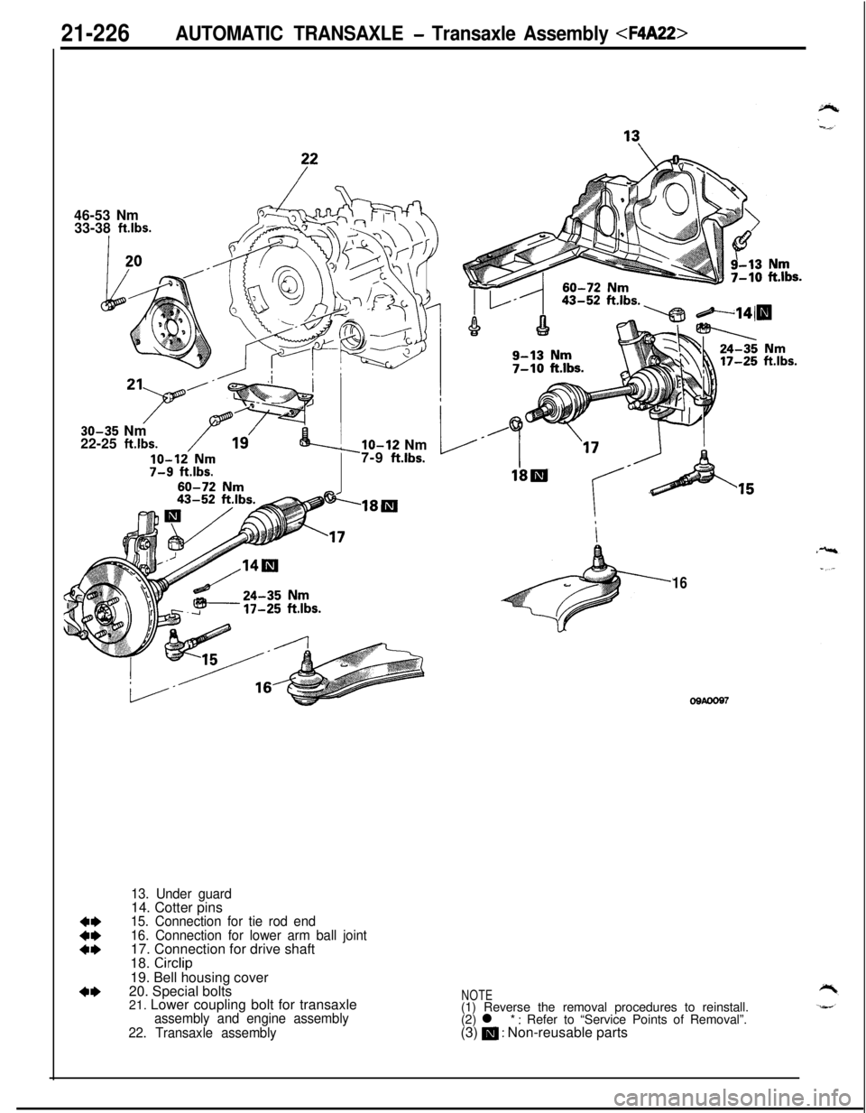
13. Under guard14. Cotter pins
15. Connection for tie rod end
16. Connection for lower arm ball joint17. Connection for drive shaft
18.
Circlip19. Bell housing cover
20. Special bolts
21. Lower coupling bolt for transaxle
assembly and engine assembly
22. Transaxle assembly
NOTE(1) Reverse the removal procedures to reinstall.
(2) l *
: Refer to “Service Points of Removal”.
(3) m : Non-reusable parts
Page 921 of 1216
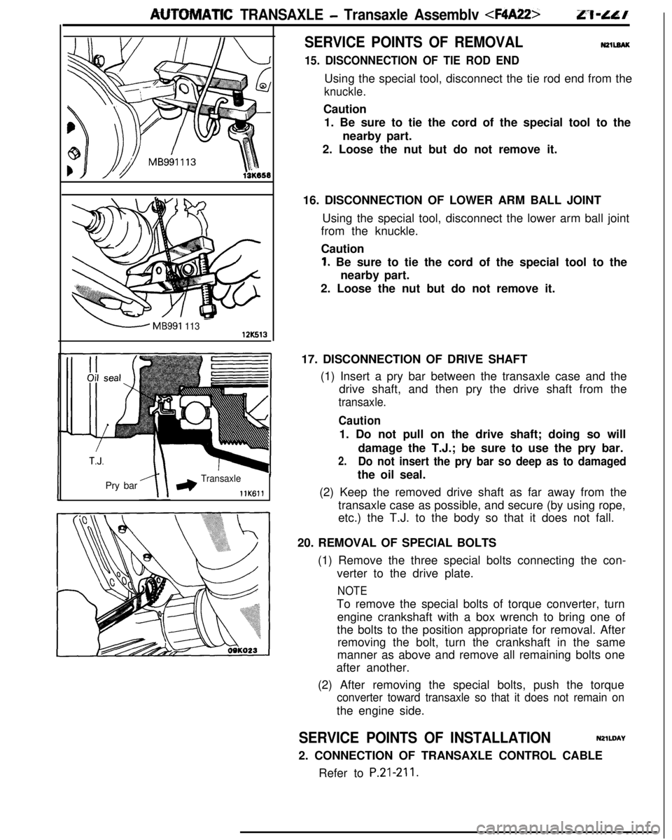
AUTOMATIC TRANSAXLE - Transaxle Assemblv
-MB991 11312K513Pry bar
*Transaxle
llK611
SERVICE POINTS OF REMOVALN2llEAK
15. DISCONNECTION OF TIE ROD ENDUsing the special tool, disconnect the tie rod end from the
knuckle.Caution
1. Be sure to tie the cord of the special tool to the
nearby part.
2. Loose the nut but do not remove it.
16. DISCONNECTION OF LOWER ARM BALL JOINT
Using the special tool, disconnect the lower arm ball joint
from the knuckle.
Caution
1. Be sure to tie the cord of the special tool to the
nearby part.
2. Loose the nut but do not remove it.
17. DISCONNECTION OF DRIVE SHAFT
(1) Insert a pry bar between the transaxle case and the
drive shaft, and then pry the drive shaft from the
transaxle.
Caution1. Do not pull on the drive shaft; doing so will
damage the T.J.; be sure to use the pry bar.
2.Do not insert the pry bar so deep as to damagedthe oil seal.
(2) Keep the removed drive shaft as far away from the
transaxle case as possible, and secure (by using rope,
etc.) the T.J. to the body so that it does not fall.
20. REMOVAL OF SPECIAL BOLTS
(1) Remove the three special bolts connecting the con-
verter to the drive plate.
NOTETo remove the special bolts of torque converter, turn
engine crankshaft with a box wrench to bring one of
the bolts to the position appropriate for removal. After
removing the bolt, turn the crankshaft in the same
manner as above and remove all remaining bolts one
after another.
(2) After removing the special bolts, push the torque
converter toward transaxle so that it does not remain onthe engine side.
SERVICE POINTS OF INSTALLATIONN2lWAY
2. CONNECTION OF TRANSAXLE CONTROL CABLE
Refer to
P.21-211.
Page 953 of 1216
AUTOMATIC TRANSAXLE - Transaxle Assembly
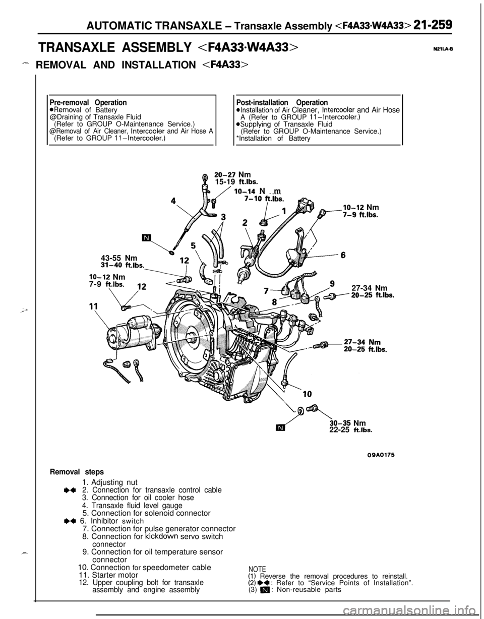
TRANSAXLE ASSEMBLY
- REMOVAL AND INSTALLATION
Pre-removal OperationPost-installation Operation*Removal of Battery*Installation of Air Cleaner, Intercooler and Air Hose@Draining of Transaxle Fluid
A (Refer to GROUP II-Intercooler.)(Refer to GROUP O-Maintenance Service.)
@Removal of Air Cleaner, Intercooler and Air Hose A*Supplying of Transaxle Fluid
(Refer to GROUP O-Maintenance Service.)
(Refer to GROUP II-Intercooler.)*Installation of Battery20-27 Nm
15-19
ft.lbs.
/ IO-14 Nm
43-55 Nm31-40
ft.lbs.
lo-12 Nm
7-9 f?.lbs.
___.Ibs.
lo-12 Nm-7-9 fi.lbs.27-34 Nm20-25
ft.lbs.30-35 Nm
22-25
ft.lbs.
09A0175
Removal steps
1. Adjusting nut+42. Connection for transaxle control cable
3. Connection for oil cooler hose
4. Transaxle fluid level gauge5. Connection for solenoid connector
e+ 6. Inhibitor switch
7. Connection for pulse generator connector
8. Connection for kickdown servo switch
connector9. Connection for oil temperature sensor
connector
10. Connection for speedometer cable
11. Starter motor
12. Upper coupling bolt for transaxle
assembly and engine assembly
NOTE(1) Reverse the removal procedures to reinstall.(2) I)+ : Refer to “Service Points of Installation”.
(3) m : Non-reusable parts