engine MITSUBISHI ECLIPSE 1991 Service Manual
[x] Cancel search | Manufacturer: MITSUBISHI, Model Year: 1991, Model line: ECLIPSE, Model: MITSUBISHI ECLIPSE 1991Pages: 1216, PDF Size: 67.42 MB
Page 1195 of 1216
HEATERS AND AIR CONDITIONING- Engine Coolant Temperature Switch24-51
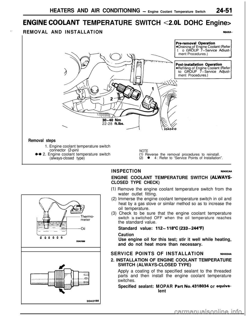
ENGINE COOLANT TEMPERATURE SWITCH <2.0L DOHC Engine>
-.REMOVAL AND INSTALLATIONN24xA-
1 to GROUP f-service Adjust-1ment Procedures.)
22-28
ft.lbs.
Removal steps1. Engine coolant temperature switch
connector (2-pin)
.4 2. Engine coolant temperature switch(always-closed type)
NOTE(1) Reverse the removal procedures to reinstall.(2) l 4 : Refer to “Service Points of Installation”.
20A0190I
INSPECTIONN24XcAAENGINE COOLANT TEMPERATURE SWITCH
(ALWAYS-
CLOSED TYPE CHECK)
(1) Remove the engine coolant temperature switch from the
water outlet fitting.
(2) Immerse the engine coolant temperature switch in oil and
heat by a gas stove or similar method so as to increase theoil temperature.
(3) Check to be sure that the engine coolant temperature
switch is switched OFF when the oil temperature reaches
the standard value.
Standard value:
112- 118°C (233-244°F)
CautionUse engine oil for this test; stir it well while heating,
and do not heat more than necessary.
SERVICE POINTS OF INSTALLATIONN24XDM2. INSTALLATION OF ENGINE COOLANT TEMPERATURE
SWITCH (ALWAYS-CLOSED TYPE)
Apply a coating of the specified sealant to the threaded
parts and then install the engine coolant temperature
switches.
Specified sealant: MOPAR Part No.4318034 or ewiva-lent
Page 1197 of 1216
.^
EMISSION CONTROL
SYSTEMS
CONTENTSN25AA-
CATALYTICCONVERTER...............................20CRANKCASE EMISSION CONTROL
SYSTEM...........................................................7Components Location
...................................7Crankcase Ventilation System
Inspection......................................................8Positive Crankcase Ventilation Valve
...........8EVAPORATIVE EMISSION CONTROL
SYSTEM...........................................................9
AirConditionerSwitch.................................14Air Flow Sensor, Engine Coolant
Temperature Sensor and Intake Air
Temperature Sensor
.....................................14
Canister.........................................................14Components Location
...................................9
FuelFillerCapInspection............................14Overfill Limiter (Two-way Valve)
..................14
PurgeControlSolenoidValve......................13Purge Control
SystemInspection................11
PurgeControlValve
SYSTEM...........................................................15Air-fuel Ratio Control (MPI) System
............20Components Location
...................................15EGR Control Solenoid Valve
.................................................19
EGR
SystemInspection...............................17EGR Temperature Sensor
......19
EGR Valve.....................................................18
Therm0 Valve
SPECIFICATIONS.............................................2General Specifications
..................................2
Sealant..........................................................2Service Specifications
...................................2
TorqueSpecifications...................................2
TROUBLESHOOTING......................................3
VACUUMHOSES...........................................4
VacuumHosesRouting...............................4
Page 1198 of 1216

EMISSION CONTROL SYSTEMS - Specifications
SPECIFICATIONS
GENERAL SPECIFICATIONSN25CA-ItemsSpecifications
.,:..rCrankcase emission control systemClosed type with positive crankcase ventilation valve”I
‘:Evaporative emission control systemCanister storage type
CanisterCharcoal type
Exhaust emission control system
Exhaust gas recirculation system
EGR valveVacuum-activated diaphragm type
Therm0 valveBimetal type
EGR temperature sensor
EGR control solenoid valve
Duty cycle solenoid valve
Catalytic converterMonolith type
LocationUnder floor
SERVICE SPECIFICATIONSN25CB-
ItemsSpecifications
Purge-control solenoid valve coil resistance
&236-44 [at 20°C (68”F)I
Therm0 valve closing temperature“C (“F)65 (149)
EGR temperature sensor resistance
kQ60-83 [at 50°C (122”F)]11-14 [at
100°C (212”F)]EGR control solenoid valve coil resistance
S236-44 [at 20°C (68”F)]
TORQUE SPECIFICATIONSN25CC-
ItemsPositive crankcase ventilation valve
EGR valve installation bolt
<2.0L DOHC Engine>
Therm0 valve
EGR temperature sensor
Nmftlbs.8-12
6-8.5
IO-157.2-1015-22
10-15.5
20-4015-30
10-127.3-8.6
SEALANT
Items
Therm0 valve thread portionSpecified sealant
MOPAR Part No.4318034 or equivalent
Page 1199 of 1216

-.
EMISSION CONTROL SYSTEMS - Troubleshooting
TROUBLESHOOTING
., ,_
SymptomProbable causeRemedy
Engine will not start or hard toVacuum hose disconnected or damaged
Repair or replacestart
The EGR valve is not closedMalfunction of the purge control solenoid
valve
Rough idle or engine stalls
The EGR valve is not closed.
Repair or replace
Vacuum hose disconnected or damagedMalfunction of the positive crankcase
ventilation valve
ReplaceMalfunction of the purge control system
Check the system; if there is a problem,
check its component parts
Engine hesitates or poor accel-Malfunction of the exhaust gas
recircula-Check the system; if there is a problem,
erationtion systemcheck its component parts
Excessive oil consumptionPositive crankcase ventilation line cloggedCheck positive crankcase ventilation sys-tem
Poor fuel mileageMalfunction of the exhaust gas recircula-Check the system; if there is a problem,tion systemcheck its component parts
Page 1200 of 1216
25-4EMISSION CONTROL SYSTEMS - Vacuum HosesVACUUM HOSES
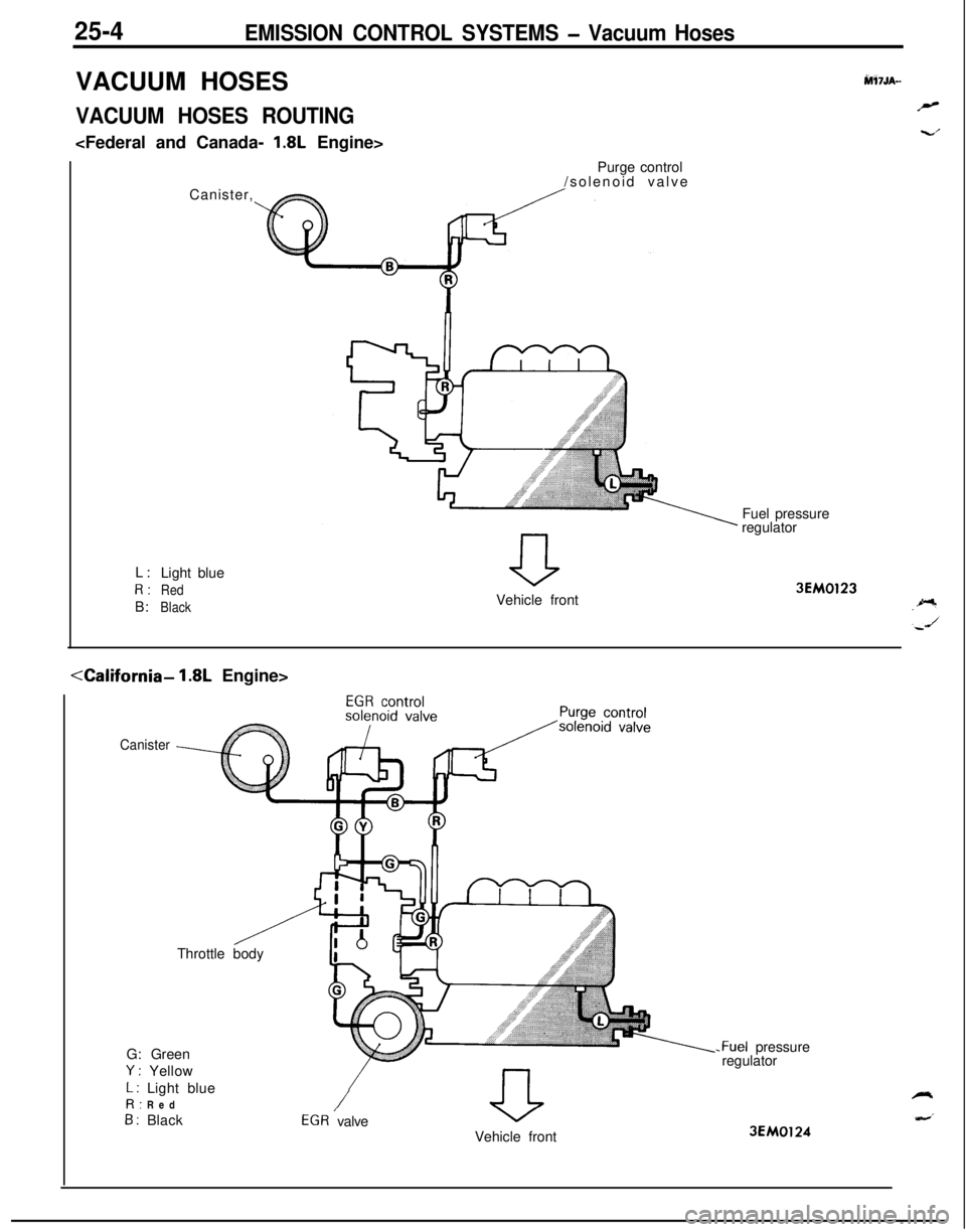
VACUUM HOSES ROUTING
hW7JA-
r”
w..’L:
Light blueR:
RedB:
BlackCanister,Purge control
/solenoid valve
Fuel pressure
regulator
Vehicle front
3EM0123
<-LCalifornia- 1.8L Engine>
CanisterThrottle body
aVehicle front G: Green
Y : Yellow
L : Light blueR: Red
B : Black/EGR valve
-Fuel pressure
regulator
3EM0124
Page 1201 of 1216
EMISSION CONTROL SYSTEMS - Vacuum Hoses2515
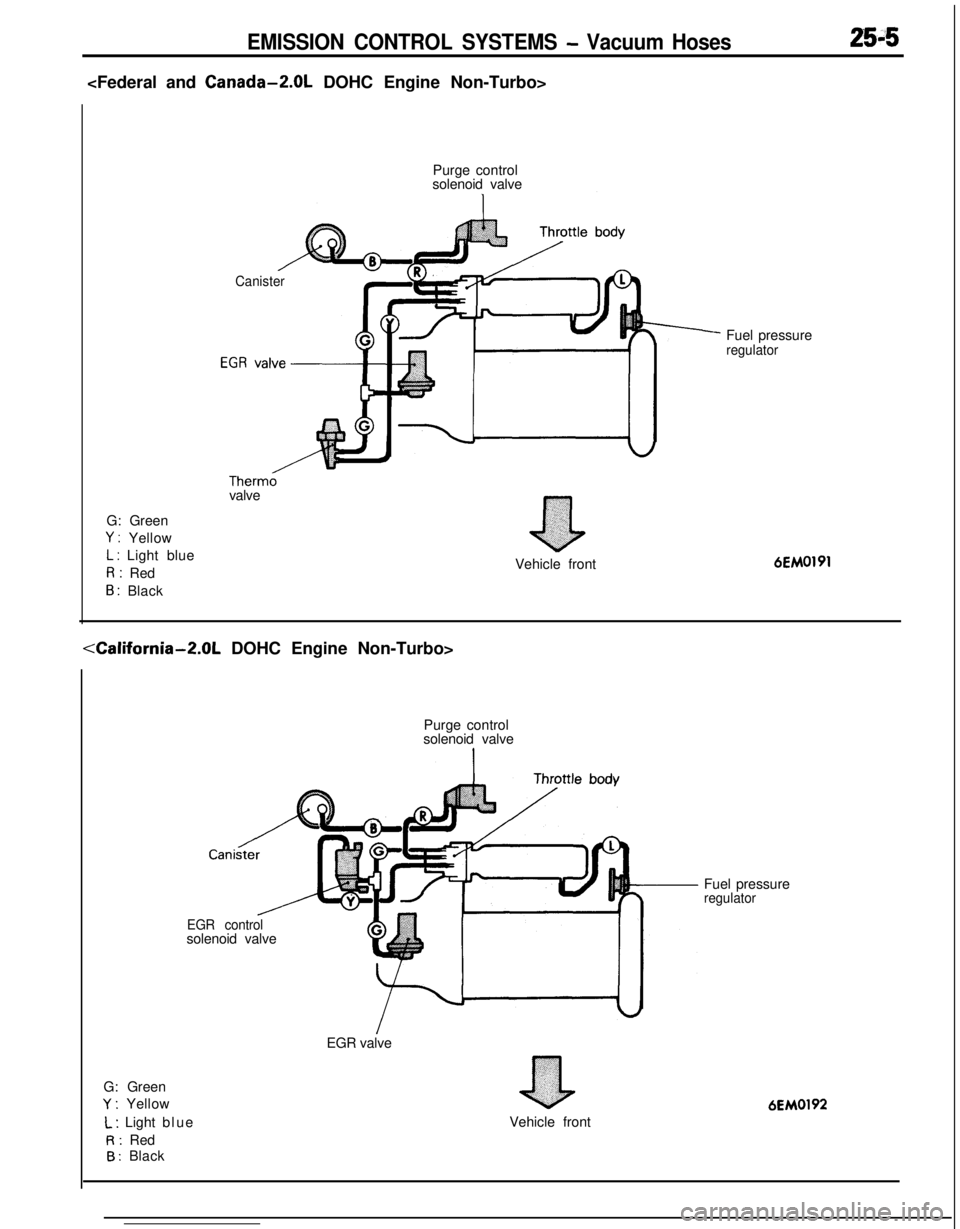
Purge control
solenoid valve
Canister
Therm0valve
G: Green
Y : Yellow
L : Light blueR: Red
B : Black
nVehicle frontFuel pressure
regulator6EM0191
G: Green
Y : YellowPurge control
solenoid valve
Cani
EGR controlsolenoid valve
EGR valve
L : Light blue
R: Red
B : BlackVehicle frontFuel pressure
regulator
6EM0192
Page 1202 of 1216

25-6EMISSION CONTROL SYSTEMS - Vacuum Hoses
G: Green
Y : Yellow
L : Light blueR: Red
B : Black
W: White
Purge control valvg
Purge controlFuel pressure control,solenoid valve/solenoid valve
Therm0 valve’
el pressure regulator
Turbocharger
vvasre gate actuator Waste gate control
solenoid valveVehicle front
6EM0222
G: Green
Y : Yellow
L : Lrght blueR: Red
B : Black
W: White
1sPurge control valve
&+
Air cleanerFuel pressure control
solenoid valve.
Purge control
solenoid valve\Fuel pressure regulator
Waste gate control
solenord valve
Waste gate actuatorv.,~~‘~y:‘;7Vehicle front
6EM0223
Page 1203 of 1216
EMISSION CONTROL SYSTEMS - vacuumHoses/Crankcase Emission Control System25-7
INSPECTION(1) Referring to the VACUUM HOSES ROUTING,
confirm2the vacuum hoses are properly connected.
(2) Check the hoses for irregularities (disconnection, loose-
ness, etc.) and confirm that there is no breakage or
damage.INSTALLATION
’N2SJDAD(1) When connecting a hose, firmly press it onto the nipple.
(2) Referring to the VACUUM HOSES ROUTING, connect the
hoses correctly.
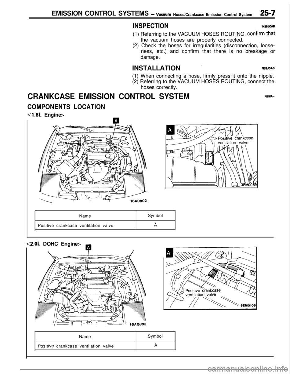
CRANKCASE EMISSION CONTROL SYSTEM
COMPONENTS LOCATION<1.8L Engine>
ventilation valve
NameSymbol
Positive crankcase ventilation valveA<2.0L DOHC Engine>
A
\T/Name
Posltive crankcase ventilation valveSymbol
A
Page 1204 of 1216
25-8EMISSION CONTROL SYSTEMS - Crankcase Emission Control System
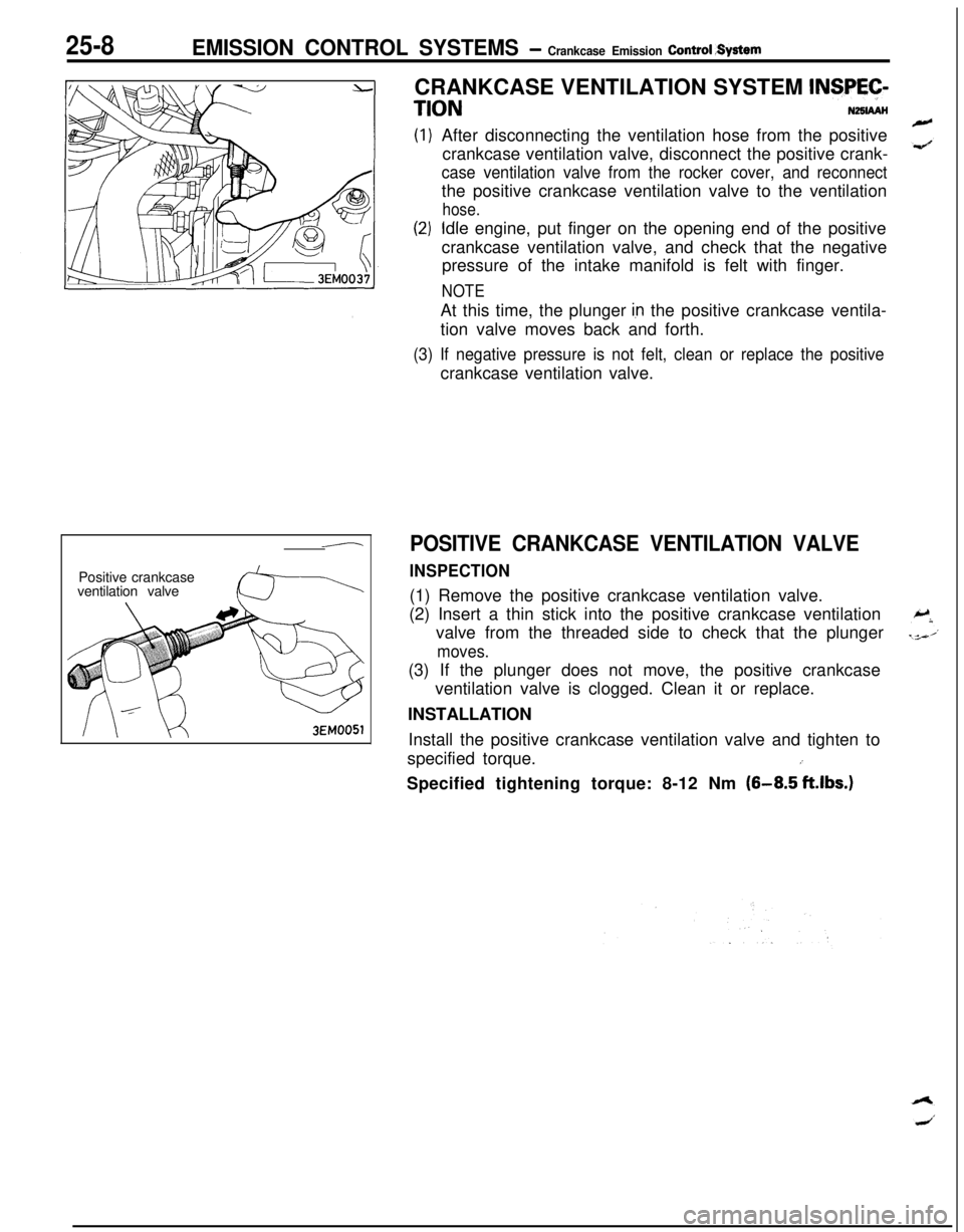
-Positive crankcase
ventilation valve3EM0051CRANKCASE VENTILATION SYSTEM
INSPEC-
TIONNZSIAAHAfter disconnecting the ventilation hose from the positive
crankcase ventilation valve, disconnect the positive crank-
case ventilation valve from the rocker cover, and reconnectthe positive crankcase ventilation valve to the ventilation
hose.
Idle engine, put finger on the opening end of the positive
crankcase ventilation valve, and check that the negative
pressure of the intake manifold is felt with finger.
NOTEAt this time, the plunger
Ian the positive crankcase ventila-
tion valve moves back and forth.
(3) If negative pressure is not felt, clean or replace the positivecrankcase ventilation valve.
POSITIVE CRANKCASE VENTILATION VALVE
INSPECTION(1) Remove the positive crankcase ventilation valve.
(2) Insert a thin stick into the positive crankcase ventilation
valve from the threaded side to check that the plunger
moves.(3) If the plunger does not move, the positive crankcase
ventilation valve is clogged. Clean it or replace.
INSTALLATION
Install the positive crankcase ventilation valve and tighten to
specified torque.
iSpecified tightening torque: 8-12 Nm
(8-8.5 ft.lbs.)
Page 1205 of 1216
EMISSION CONTROL SYSTEMS- Evaporative Emission Control System
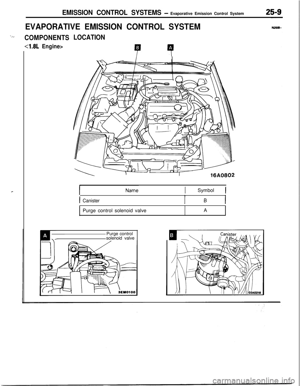
EVAPORATIVE EMISSION CONTROL SYSTEM
‘2,COMPONENTS
4.81,Engine>
r
LOCATION
P 4
xl-#i
ISymbol 1
ICanisterPurge control solenoid valveA
Purge control
solenoid valve