MITSUBISHI ENDEAVOR 2004 Service Repair Manual
ENDEAVOR 2004
MITSUBISHI
MITSUBISHI
https://www.carmanualsonline.info/img/19/57105/w960_57105-0.png
MITSUBISHI ENDEAVOR 2004 Service Repair Manual
Trending: spark plug, windshield wipers, suspension, rear entertainment, Rear hub, power steering fluid, brake fluid
Page 2691 of 3870
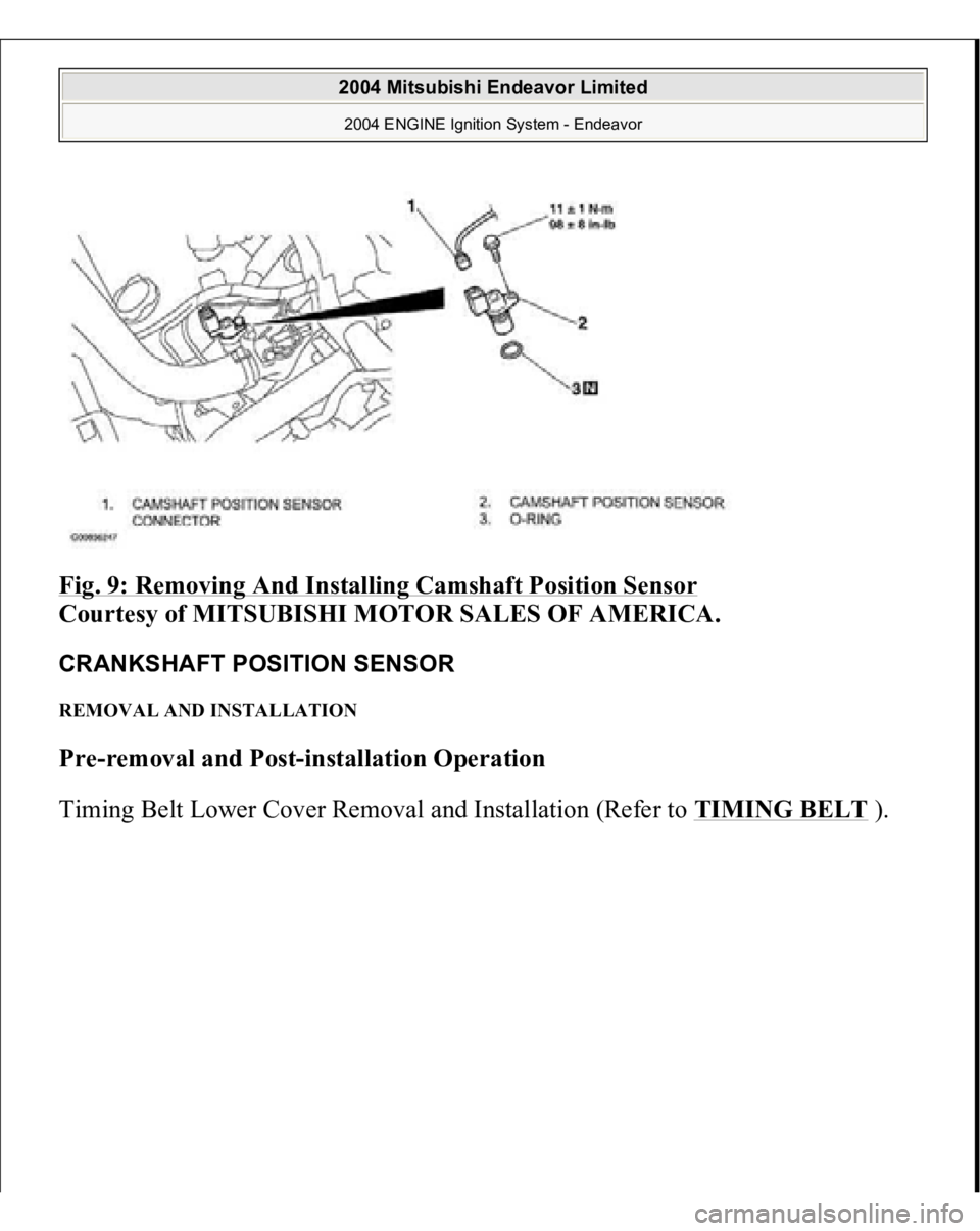
Fig. 9: Removing And Installing Camshaft Position Sensor
Courtesy of MITSUBISHI MOTOR SALES OF AMERICA.
CRANKSHAFT POSITION SENSOR REMOVAL AND INSTALLATION Pre-removal and Post-installation Operation
Timin
g Belt Lower Cover Removal and Installation
(Refer to TIMING BELT
).
2004 Mitsubishi Endeavor Limited 2004 ENGINE Ignition System - Endeavor
Page 2692 of 3870
Fig. 10: Removing And Installing Crankshaft Position Sensor
Courtesy of MITSUBISHI MOTOR SALES OF AMERICA.
KNOCK SENSOR REMOVAL AND INSTALLATION Pre-removal and Post-installation Operation
Intake Manifold Removal and Installation (Refer to REMOVAL AND INSTALLATION
).
2004 Mitsubishi Endeavor Limited 2004 ENGINE Ignition System - Endeavor
Page 2693 of 3870
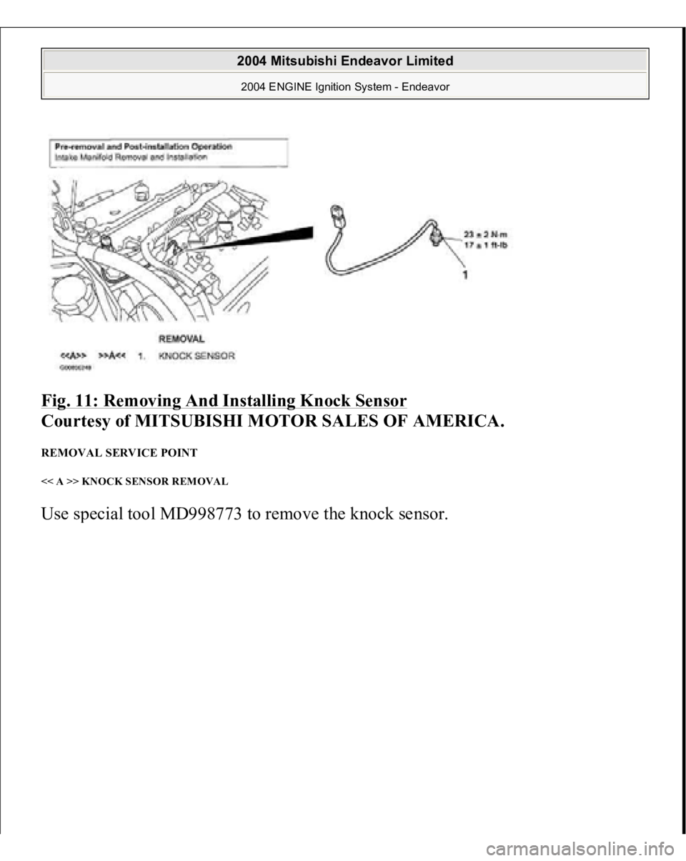
Fig. 11: Removing And Installing Knock Sensor
Courtesy of MITSUBISHI MOTOR SALES OF AMERICA.
REMOVAL SERVICE POINT << A >> KNOCK SENSOR REMOVAL Use s
pecial tool MD998773 to remove the knock sensor.
2004 Mitsubishi Endeavor Limited 2004 ENGINE Ignition System - Endeavor
Page 2694 of 3870
Fig. 12: Removing Knock Sensor Using Special Tool (MD998773)
Courtesy of MITSUBISHI MOTOR SALES OF AMERICA.
INSTALLATION SERVICE POINT >>A<< KNOCK SENSOR INSTALLATION Use special tool MD998773 to install the knock sensor. SPECIFICATIONS FASTENER TIGHTENING SPECIFICATIONS
2004 Mitsubishi Endeavor Limited 2004 ENGINE Ignition System - Endeavor
Page 2695 of 3870
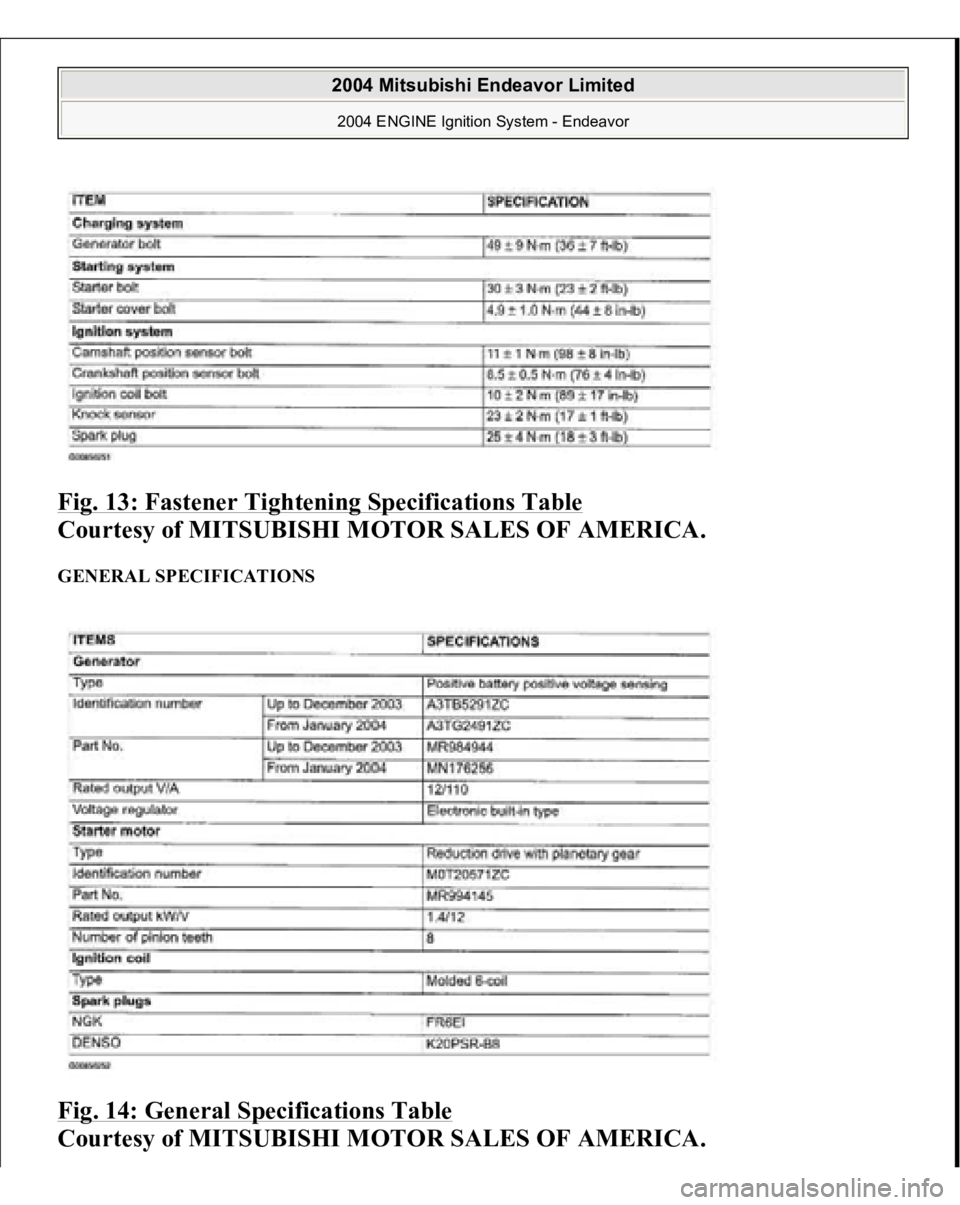
Fig. 13: Fastener Tightening Specifications Table
Courtesy of MITSUBISHI MOTOR SALES OF AMERICA.
GENERAL SPECIFICATIONS Fig. 14: General Specifications Table
Courtesy of MITSUBISHI MOTOR SALES OF AMERICA.
2004 Mitsubishi Endeavor Limited 2004 ENGINE Ignition System - Endeavor
Page 2696 of 3870
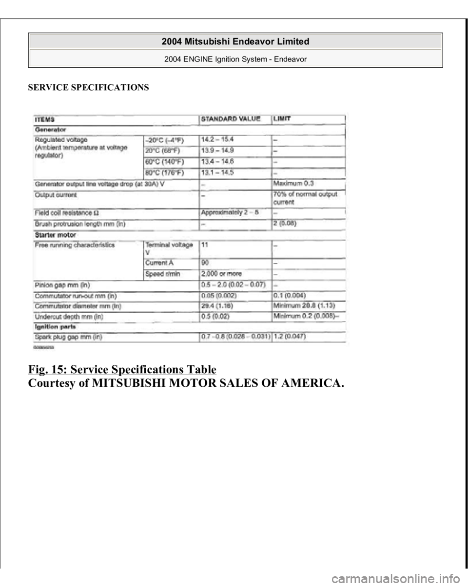
SERVICE SPECIFICATIONS Fig. 15: Service Specifications Table
Courtesy of MITSUBISHI MOTOR SALES OF AMERICA.
2004 Mitsubishi Endeavor Limited 2004 ENGINE Ignition System - Endeavor
Page 2697 of 3870
2004 BODY & ACCESSORIES
Instrument Panel Assembly - Endeavor
INSTRUMENT PANEL ASSEMBLY REMOVAL AND INSTALLATION The following bolts and screws are used for installing the instrument panel. Bolts
and screws are indicated as marks shown in the illustration in the sections of
"Removal and Installation" and "Disassembly and Assembly.
"
CAUTION:
For removal and installation of the passenger's
side air bag module, always observer the service
procedures described in AIR BAG RESTRAINT SYSTEMS
.
Refer to AIR BAG RESTRAINT SYSTEMS
. before
removing the passenger side air bag module.
Do not subject the SRS-ECU to any shocks when
removing or installing the instrument panel.
2004 Mitsubishi Endeavor XLS
2004 BODY & ACCESSORIES Instrument Panel Assembly - Endeavor
2004 Mitsubishi Endeavor XLS
2004 BODY & ACCESSORIES Instrument Panel Assembly - Endeavor
Page 2698 of 3870
Fig. 1: Bolts And Screws Specification Chart
Courtesy of MITSUBISHI MOTOR SALES OF AMERICA.
2004 Mitsubishi Endeavor XLS
2004 BODY & ACCESSORIES Instrument Panel Assembly - Endeavor
Page 2699 of 3870
Fig. 2: Exploded View Of Instrument Panel (1 Of 2)
Courtesy of MITSUBISHI MOTOR SALES OF AMERICA.
2004 Mitsubishi Endeavor XLS
2004 BODY & ACCESSORIES Instrument Panel Assembly - Endeavor
Page 2700 of 3870
Fig. 3: Instrument Panel Legend
Courtesy of MITSUBISHI MOTOR SALES OF AMERICA.
CLIP AND CLAW POSITIONS
2004 Mitsubishi Endeavor XLS
2004 BODY & ACCESSORIES Instrument Panel Assembly - Endeavor
Trending: Jack point, ABS rear brakes, air suspension, turn signal, steering wheel adjustment, coolant temperature, wiper fluid
