MITSUBISHI ENDEAVOR 2004 Service Repair Manual
ENDEAVOR 2004
MITSUBISHI
MITSUBISHI
https://www.carmanualsonline.info/img/19/57105/w960_57105-0.png
MITSUBISHI ENDEAVOR 2004 Service Repair Manual
Trending: keyless, remote control, Jack point, fuse box, horn, lights, camshaft
Page 3151 of 3870
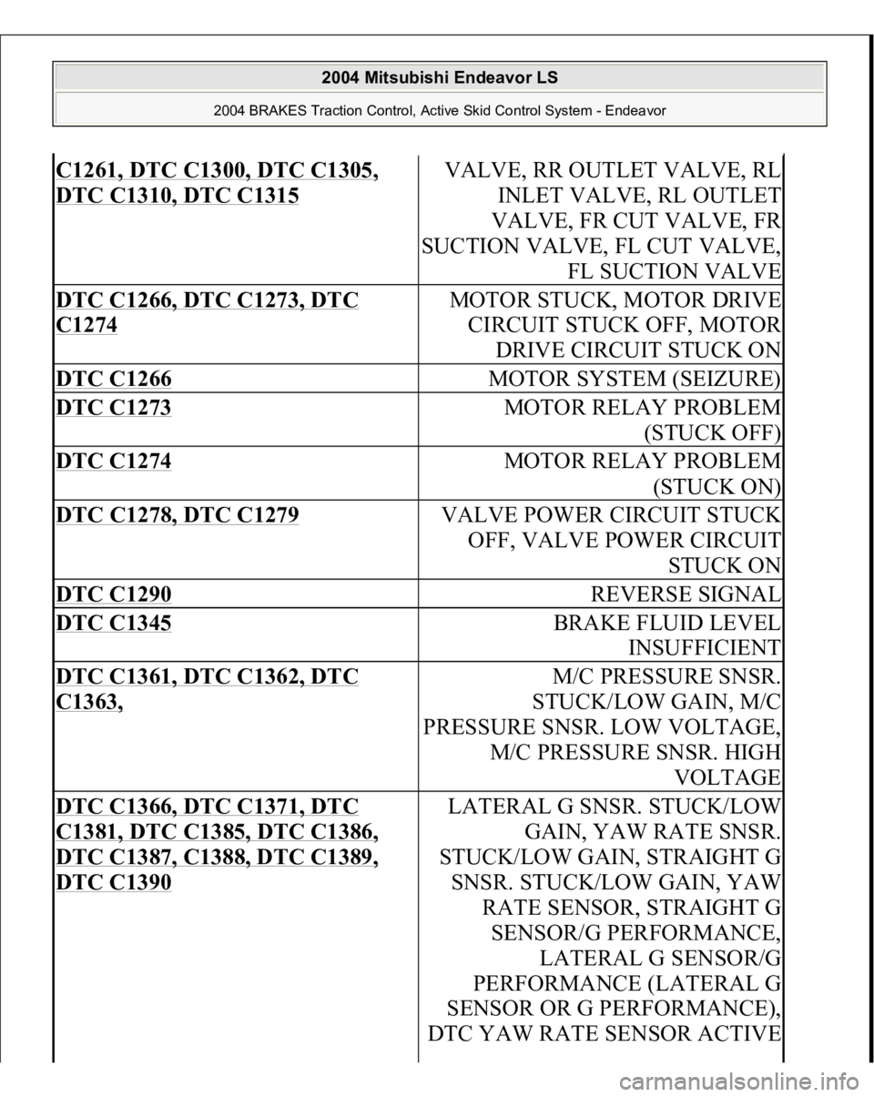
C1261, DTC C1300, DTC C1305, DTC C1310, DTC C1315
VALVE, RR OUTLET VALVE, RL
INLET VALVE, RL OUTLET
VALVE, FR CUT VALVE, FR
SUCTION VALVE, FL CUT VALVE,
FL SUCTION VALVE
DTC C1266, DTC C1273, DTC C1274
MOTOR STUCK, MOTOR DRIVE
CIRCUIT STUCK OFF, MOTOR
DRIVE CIRCUIT STUCK ON
DTC C1266
MOTOR SYSTEM (SEIZURE)
DTC C1273
MOTOR RELAY PROBLEM
(STUCK OFF)
DTC C1274
MOTOR RELAY PROBLEM
(STUCK ON)
DTC C1278, DTC C1279
VALVE POWER CIRCUIT STUCK
OFF, VALVE POWER CIRCUIT
STUCK ON
DTC C1290
REVERSE SIGNAL
DTC C1345
BRAKE FLUID LEVEL
INSUFFICIENT
DTC C1361, DTC C1362, DTC C1363,
M/C PRESSURE SNSR.
STUCK/LOW GAIN, M/C
PRESSURE SNSR. LOW VOLTAGE,
M/C PRESSURE SNSR. HIGH
VOLTAGE
DTC C1366, DTC C1371, DTC C1381, DTC C1385, DTC C1386, DTC C1387, C1388, DTC C1389, DTC C1390
LATERAL G SNSR. STUCK/LOW
GAIN, YAW RATE SNSR.
STUCK/LOW GAIN, STRAIGHT G
SNSR. STUCK/LOW GAIN, YAW
RATE SENSOR, STRAIGHT G
SENSOR/G PERFORMANCE,
LATERAL G SENSOR/G
PERFORMANCE (LATERAL G
SENSOR OR G PERFORMANCE),
DTC YAW RATE SENSOR ACTIVE
2004 Mitsubishi Endeavor LS
2004 BRAKES Traction Control, Active Skid Control System - Endeavor
Page 3152 of 3870
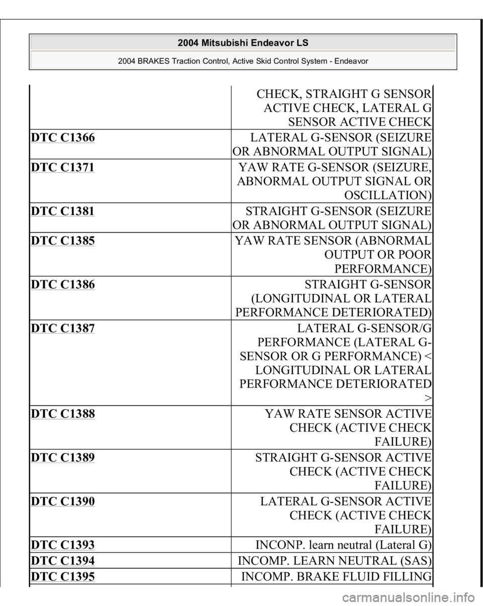
CHECK, STRAIGHT G SENSOR
ACTIVE CHECK, LATERAL G
SENSOR ACTIVE CHECK
DTC C1366
LATERAL G-SENSOR (SEIZURE
OR ABNORMAL OUTPUT SIGNAL)
DTC C1371
YAW RATE G-SENSOR (SEIZURE,
ABNORMAL OUTPUT SIGNAL OR
OSCILLATION)
DTC C1381
STRAIGHT G-SENSOR (SEIZURE
OR ABNORMAL OUTPUT SIGNAL)
DTC C1385
YAW RATE SENSOR (ABNORMAL
OUTPUT OR POOR
PERFORMANCE)
DTC C1386
STRAIGHT G-SENSOR
(LONGITUDINAL OR LATERAL
PERFORMANCE DETERIORATED)
DTC C1387
LATERAL G-SENSOR/G
PERFORMANCE (LATERAL G-
SENSOR OR G PERFORMANCE) <
LONGITUDINAL OR LATERAL
PERFORMANCE DETERIORATED
>
DTC C1388
YAW RATE SENSOR ACTIVE
CHECK (ACTIVE CHECK
FAILURE)
DTC C1389
STRAIGHT G-SENSOR ACTIVE
CHECK (ACTIVE CHECK
FAILURE)
DTC C1390
LATERAL G-SENSOR ACTIVE
CHECK (ACTIVE CHECK
FAILURE)
DTC C1393
INCONP. learn neutral (Lateral G)
DTC C1394
INCOMP. LEARN NEUTRAL (SAS)
DTC C1395
INCOMP. BRAKE FLUID FILLING
2004 Mitsubishi Endeavor LS
2004 BRAKES Traction Control, Active Skid Control System - Endeavor
Page 3153 of 3870
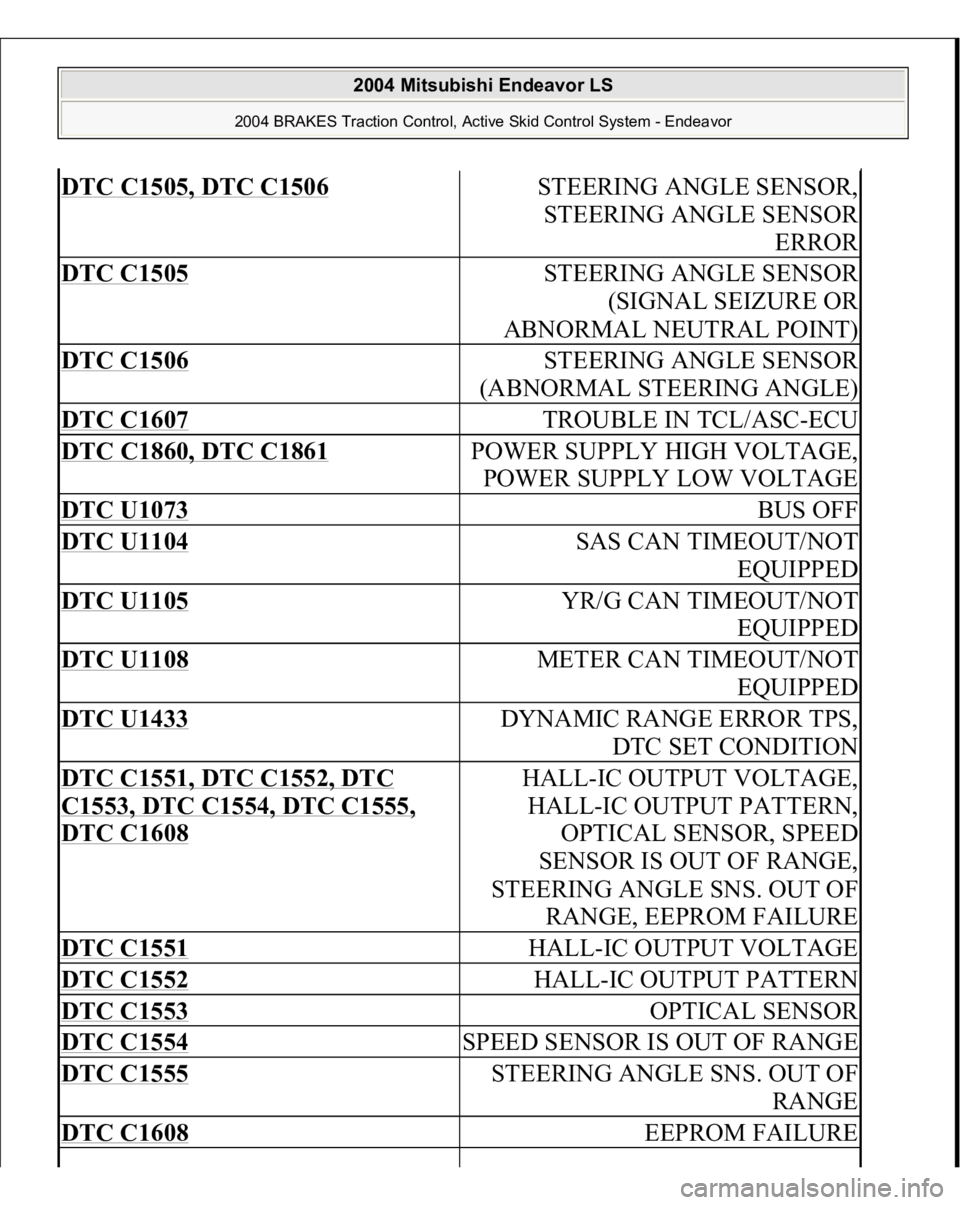
DTC C1505, DTC C1506
STEERING ANGLE SENSOR,
STEERING ANGLE SENSOR
ERROR
DTC C1505
STEERING ANGLE SENSOR
(SIGNAL SEIZURE OR
ABNORMAL NEUTRAL POINT)
DTC C1506
STEERING ANGLE SENSOR
(ABNORMAL STEERING ANGLE)
DTC C1607
TROUBLE IN TCL/ASC-ECU
DTC C1860, DTC C1861
POWER SUPPLY HIGH VOLTAGE,
POWER SUPPLY LOW VOLTAGE
DTC U1073
BUS OFF
DTC U1104
SAS CAN TIMEOUT/NOT
EQUIPPED
DTC U1105
YR/G CAN TIMEOUT/NOT
EQUIPPED
DTC U1108
METER CAN TIMEOUT/NOT
EQUIPPED
DTC U1433
DYNAMIC RANGE ERROR TPS,
DTC SET CONDITION
DTC C1551, DTC C1552, DTC C1553, DTC C1554, DTC C1555, DTC C1608
HALL-IC OUTPUT VOLTAGE,
HALL-IC OUTPUT PATTERN,
OPTICAL SENSOR, SPEED
SENSOR IS OUT OF RANGE,
STEERING ANGLE SNS. OUT OF
RANGE, EEPROM FAILURE
DTC C1551
HALL-IC OUTPUT VOLTAGE
DTC C1552
HALL-IC OUTPUT PATTERN
DTC C1553
OPTICAL SENSOR
DTC C1554
SPEED SENSOR IS OUT OF RANGE
DTC C1555
STEERING ANGLE SNS. OUT OF
RANGE
DTC C1608
EEPROM FAILURE
2004 Mitsubishi Endeavor LS
2004 BRAKES Traction Control, Active Skid Control System - Endeavor
Page 3154 of 3870
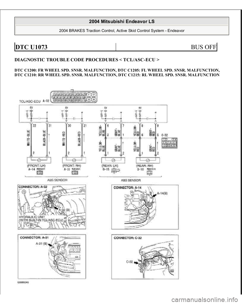
DIAGNOSTIC TROUBLE CODE PROCEDURES < TCL/ASC-ECU > DTC C1200: FR WHEEL SPD. SNSR. MALFUNCTION, DTC C1205: FL WHEEL SPD. SNSR. MALFUNCTION,
DTC C1210: RR WHEEL SPD. SNSR. MALFUNCTION, DTC C1215: RL WHEEL SPD. SNSR. MALFUNCTION DTC U1073
BUS OFF
2004 Mitsubishi Endeavor LS
2004 BRAKES Traction Control, Active Skid Control System - Endeavor
Page 3155 of 3870
Fig. 40: TCL/ASC Sensor Circuit Diagram & Connector Identificatio
n
Courtesy of MITSUBISHI MOTOR SALES OF AMERICA.
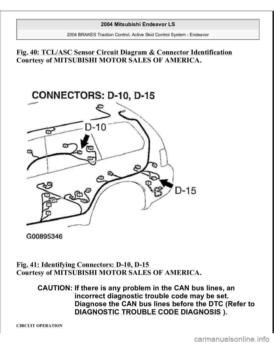
Fig. 41: Identifying Connectors: D
-10, D
-15
Courtesy of MITSUBISHI MOTOR SALES OF AMERICA.
CIRCUIT OPERATION
CAUTION: If there is any problem in the CAN bus lines, an
incorrect diagnostic trouble code may be set.
Diagnose the CAN bus lines before the DTC (Refer to
DIAGNOSTIC TROUBLE CODE DIAGNOSIS
).
2004 Mitsubishi Endeavor LS
2004 BRAKES Traction Control, Active Skid Control System - Endeavor
Page 3156 of 3870
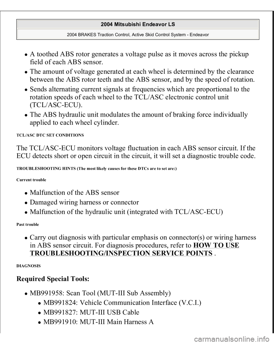
A toothed ABS rotor generates a voltage pulse as it moves across the pickup
field of each ABS sensor. The amount of voltage generated at each wheel is determined by the clearance
between the ABS rotor teeth and the ABS sensor, and by the speed of rotation. Sends alternating current signals at frequencies which are proportional to the
rotation speeds of each wheel to the TCL/ASC electronic control unit
(TCL/ASC-ECU). The ABS hydraulic unit modulates the amount of braking force individually
applied to each wheel cylinder.
TCL/ASC DTC SET CONDITIONS The TCL/ASC-ECU monitors voltage fluctuation in each ABS sensor circuit. If the
ECU detects short or open circuit in the circuit, it will set a diagnostic trouble code. TROUBLESHOOTING HINTS (The most likely causes for these DTCs are to set are:)
Current trouble
Malfunction of the ABS sensor Damaged wiring harness or connector Malfunction of the hydraulic unit (integrated with TCL/ASC-ECU)
Past trouble
Carry out diagnosis with particular emphasis on connector(s) or wiring harness
in ABS sensor circuit. For diagnosis procedures, refer to HOW TO USE TROUBLESHOOTING/INSPECTION SERVICE POINTS
.
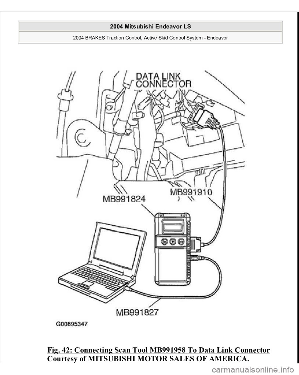
DIAGNOSIS Required Special Tools:
MB991958: Scan Tool (MUT-III Sub Assembly)
MB991824: Vehicle Communication Interface (V.C.I.) MB991827: MUT-III USB Cable MB991910: MUT-III Main Harness A
2004 Mitsubishi Endeavor LS
2004 BRAKES Traction Control, Active Skid Control System - Endeavor
Page 3157 of 3870
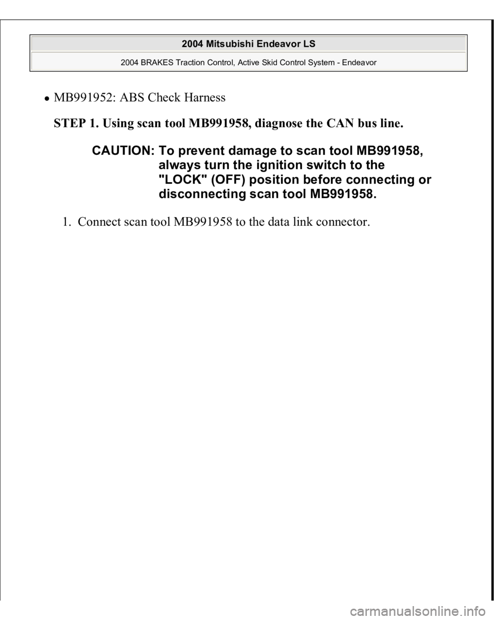
MB991952: ABS Check Harness
STEP 1. Using scan tool MB991958, diagnose the CAN bus line.
1. Connect scan tool MB991958 to the data link connec
tor.
CAUTION: To prevent damage to scan tool MB991958,
always turn the ignition switch to the
"LOCK" (OFF) position before connecting or
disconnecting scan tool MB991958.
2004 Mitsubishi Endeavor LS
2004 BRAKES Traction Control, Active Skid Control System - Endeavor
Page 3158 of 3870
Fig. 42: Connecting Scan Tool MB991958 To Data Link Connector
Courtesy of MITSUBISHI MOTOR SALES OF AMERICA.
2004 Mitsubishi Endeavor LS
2004 BRAKES Traction Control, Active Skid Control System - Endeavor
Page 3159 of 3870
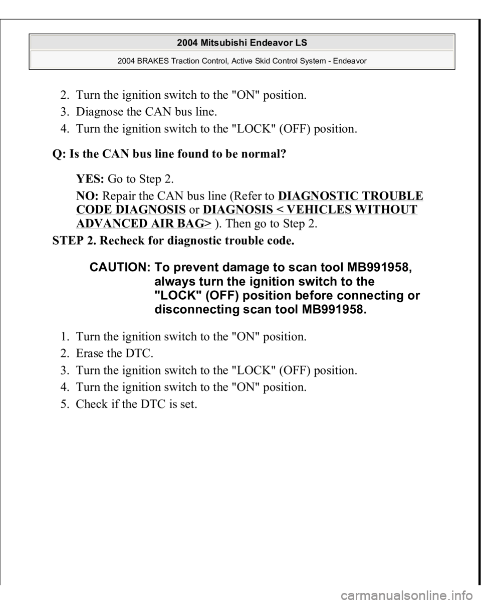
2. Turn the ignition switch to the "ON" position.
3. Diagnose the CAN bus line.
4. Turn the ignition switch to the "LOCK" (OFF) position.
Q: Is the CAN bus line found to be normal?
YES: Go to Step 2.
NO: Repair the CAN bus line (Refer to DIAGNOSTIC TROUBLE
CODE DIAGNOSIS
or DIAGNOSIS < VEHICLES WITHOUT
ADVANCED AIR BAG>
). Then go to Step 2.
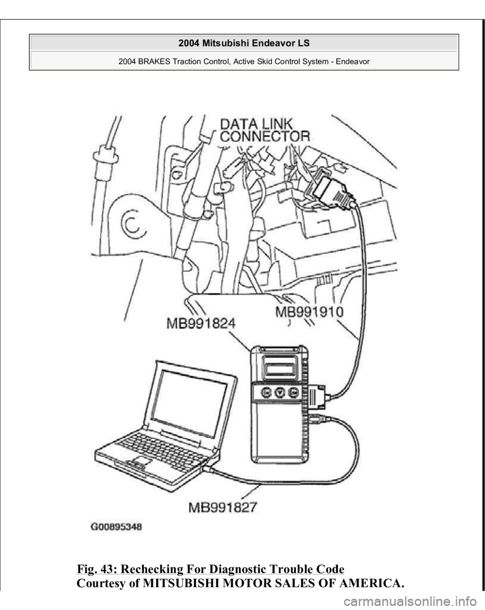
STEP 2. Recheck for diagnostic trouble code.
1. Turn the ignition switch to the "ON" position.
2. Erase the DTC.
3. Turn the ignition switch to the "LOCK" (OFF) position.
4. Turn the ignition switch to the "ON" position.
5. Check if the DTC is set.
CAUTION: To prevent damage to scan tool MB991958,
always turn the ignition switch to the
"LOCK" (OFF) position before connecting or
disconnecting scan tool MB991958.
2004 Mitsubishi Endeavor LS
2004 BRAKES Traction Control, Active Skid Control System - Endeavor
Page 3160 of 3870
Fig. 43: Rechecking For Diagnostic Trouble Code
Courtes
y of MITSUBISHI MOTOR SALES OF AMERICA
.
2004 Mitsubishi Endeavor LS
2004 BRAKES Traction Control, Active Skid Control System - Endeavor
Trending: alarm, sport mode, engine diagram, heater, headlights, wheel alignment, service reset

