MITSUBISHI GALANT 1989 Service Repair Manual
Manufacturer: MITSUBISHI, Model Year: 1989, Model line: GALANT, Model: MITSUBISHI GALANT 1989Pages: 1273, PDF Size: 37.62 MB
Page 1151 of 1273
![MITSUBISHI GALANT 1989 Service Repair Manual 35-30SERVICE BRAKES - Anti-lock Braking System Troubleshooting
E-3When diagnostic trouble code “22 STOP SW” is displayed1
[Explanation][Hint]
The ABS ECU outputs this diagnostic trouble codeIf the MITSUBISHI GALANT 1989 Service Repair Manual 35-30SERVICE BRAKES - Anti-lock Braking System Troubleshooting
E-3When diagnostic trouble code “22 STOP SW” is displayed1
[Explanation][Hint]
The ABS ECU outputs this diagnostic trouble codeIf the](/img/19/57312/w960_57312-1150.png)
35-30SERVICE BRAKES - Anti-lock Braking System Troubleshooting
E-3When diagnostic trouble code “22 STOP SW” is displayed1
[Explanation][Hint]
The ABS ECU outputs this diagnostic trouble codeIf the stop light operates normal, the ABS harness
in the following cases.wire for the stop light switch input circuit to the ECU
lStop light switch may remain on for more thanis broken or there is a malfunction in the ABS ECU.
15 minutes without the ABS functions.
lThe harness wire for the stop light switch may be open.
SUB FUSIBLELINK @
ABSECU
[1121314/5161716~9~10~11~12~13~14~15(16~17~18]~19DOC1122~3~4125l26~27~2~2913013ll3Z~33(341351
Do the stop lights light up
and go out normally?No c Check the stop light re-
lated circuit and repair
problem spots.
Yes
connector and inspectat
the harness side connec-
When the brake pedal is
_NoHarness wire between
pressed forcefully, does the
voltage between connector stop light switch and ABS
ECU is broken.
terminal No. 29 and ground
indicate battery voltage?
c
Repair harness.
Yes r
Malfunction of ABS ECU Replace ABS ECU.
I
14AO683
TSB Revision
Page 1152 of 1273
![MITSUBISHI GALANT 1989 Service Repair Manual SERVICE BRAKES -Anti-lock Braking System Troubleshooting35-31
E-4When diagnostic trouble codes “41 SOL
V
FRONT L”, “42 SOL V FRONT R” OR “43
SOL V
REAR” are displayed
[Explanation]
The MITSUBISHI GALANT 1989 Service Repair Manual SERVICE BRAKES -Anti-lock Braking System Troubleshooting35-31
E-4When diagnostic trouble codes “41 SOL
V
FRONT L”, “42 SOL V FRONT R” OR “43
SOL V
REAR” are displayed
[Explanation]
The](/img/19/57312/w960_57312-1151.png)
SERVICE BRAKES -Anti-lock Braking System Troubleshooting35-31
E-4When diagnostic trouble codes “41 SOL
V
FRONT L”, “42 SOL V FRONT R” OR “43
SOL V
REAR” are displayed
[Explanation]
The ABS ECU normally monitors the solenoid valve
drive circuit.
If no current flows in the solenoid even if the ECU
turns the solenoid ON or if it continues to flow even when turned OFF, the ECU determines the solenoid
coil wire is broken/short circuited or the harness is
broken short circuited and then these diagnostic
trouble codes are output.
IGNITION
SWITCH
(IGl)
U
0
&
cY10
2: p:\
,8 , ---------7HUI1 I
Ll 12 [ 3 14 [ 5 16 1 7 18 ~9110/11112113114115116117l18I~19~0~1~22~3~24~25~26~27~28)29~30~31~32~33~~~35~
tor and check with the HU
\/
Is the resistance value for the
solenoid valve, that the dis-
played diagnostic troublecode indicates, within the
range of the standard values?
Standard value:
1.07-1.17 52
Is the solenoid valve resist-
ance value, that the output
diagnostic trouble code dis- plays, within the range of the
standard values when mea-sured at the ECU connector?
Standard value:
1.07-1.17 Q
Replace HU.
NoThe harness wire for the
solenoid valve
circuit
whose resistance value is outside the range of thestandard value is broken
or short circuited.
I
Repair ABS harness.
Malfunction of ABS ECU Replace ABS ECU.
I
TSB Revision
Page 1153 of 1273
![MITSUBISHI GALANT 1989 Service Repair Manual 35-32SERVICE BRAKES - Anti-lock Braking System Troubleshooting
E-5When diagnostic trouble code “51 VALVE RLY” is displayed
[Explanation]
When the ignition switch is turned ON, the ABSnormal. In ad MITSUBISHI GALANT 1989 Service Repair Manual 35-32SERVICE BRAKES - Anti-lock Braking System Troubleshooting
E-5When diagnostic trouble code “51 VALVE RLY” is displayed
[Explanation]
When the ignition switch is turned ON, the ABSnormal. In ad](/img/19/57312/w960_57312-1152.png)
35-32SERVICE BRAKES - Anti-lock Braking System Troubleshooting
E-5When diagnostic trouble code “51 VALVE RLY” is displayed
[Explanation]
When the ignition switch is turned ON, the ABSnormal. In addition, normally it monitors whether or
ECU switches the valve relay OFF and ON for annot there is power in the valve power monitor line
initial check, compares the voltage of the signal tosince the valve relay is normally ON. Then, if the
the valve relay and valve power monitor line voltage supply of power to the valve power monitor line is
to check whether the valv
e
relay operation is interrupted, this diagnostic trouble code will output.
IGNITIONMAIN FUSIBLESWITCHLINK @ (IGl)
1440679\/
I
When the valve relay is
checked, are the following
conditions found?
No.85-No.86:resistance
value 60-120 QNo. 30-No. 87a: continuityNo.30-No.87: No continui-
t
y
When battery voltage is ap-
plied between terminalsNo. 86 and No.85
grounded.
No.30-No.87: continuityNo.30-No.87a: no continui-
t
y
Yes
the valve relay and
remove the HU connec-
>
NoValve relay malfunction
I
Replace valve relay. I
With the ignition key “ON”, does the voltage between
No ~
HU power harness wire is
broken?,-
the connector terminal No.12 and ground indicate bat-
tery voltage?I
Repair harness.
YesI
Connect the HU harness
and remove the ECUcon-nector.>
Does resistance betweenNo c Malfunction of harness
body connector terminal between HU and ECU No.2
and terminal No.27
in-
dicate
60-120 ohm?I
I Yes
TSB Revision
Replace ABS ECU.I
Page 1154 of 1273
![MITSUBISHI GALANT 1989 Service Repair Manual MAIN FUSIBLE
LINK @
SERVICE BRAKES - Anti-lock Braking System Troubleshooting35-33
E-6When diagnostic trouble code “52 MOTOR RLY” is displayed
[Explanation][Hint]
The ABS ECU outputs this diagnost MITSUBISHI GALANT 1989 Service Repair Manual MAIN FUSIBLE
LINK @
SERVICE BRAKES - Anti-lock Braking System Troubleshooting35-33
E-6When diagnostic trouble code “52 MOTOR RLY” is displayed
[Explanation][Hint]
The ABS ECU outputs this diagnost](/img/19/57312/w960_57312-1153.png)
MAIN FUSIBLE
LINK @
SERVICE BRAKES - Anti-lock Braking System Troubleshooting35-33
E-6When diagnostic trouble code “52 MOTOR RLY” is displayed
[Explanation][Hint]
The ABS ECU outputs this diagnostic trouble code forIf there is motor operation noise when wheel speed
the motor relay and motor in the following cases.
exceeds Gkm/h (4mph) when starting up after the
l When the motor relay does not function
engine is started, or when there is forced scan tool
lWhen there is trouble with the motor itself and itdrive, there is a broken or short circuited motor
does not revolve
monitor wire.
lWhen the motor ground line is disconnected and
the motor does not revolve
l When the motor continues to revolve Does the motor make a
YesBroken wire or short cir-noise when wheel speed)
1
cuit in motor monitor line
exceeds 6 km/h (4 mph) or1
[ 1 ,2
/ 3 14 15 I6 1 I 18 I9l10l11112113114115116117l1sJ~l9~0~1~2tz3l2~~25t6~27~2~29~~~31~32b3134135/
14A0684
L
Remove the motor relay andcheck resistance values.No. 85-No. 86:resistancevalue 30-60 9No. 30-No. 87: no continui-
Motor relay malfunction
4
Replace motor relay.I
tYBattery voltage is applied onterminals No.85 and No.86grounded.No. 30-No. 87: continuity
Yes
Is pump motor ground con-netted normally? Connect ground wire.
\/i
Does voltage between bodyBroken wire in pump
connector terminal 11 andNo *motor power circuit
ground indicate battery vol-
tage?
1
Repair the harness.
Yes
Connect the HU
tonnetor and remove theECUconnector.
I
Is resistance between bodyNo - Malfunction of harness
connector terminal No. 2 and- between HU and ECU No.26 30-60 ohms?
1 Yes
Is resistance between ECUharness side connector ter- NO
minal No. 5 and ground 0.1 -0.3 ohm?
Yes
ABS ECU malfunction
1 TSB Revision
Replace ABS ECU.
Page 1155 of 1273
35-34SERVICE BRAKES - Anti-lock Braking System Troubleshooting
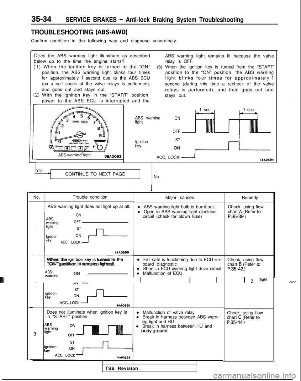
TROUBLESHOOTING (ABS-AWD)
Confirm condition in the following way and diagnose accordingly.
c
P
t:
1
-)oes
the ABS warning light illuminate as described
elow up to the time the engine starts?
1) When the ignition key is turned to the “ON”
position, the ABS warning light blinks four times
for approximately
1 second due to the ABS ECU
(as a self check of the valve relays is performed),
and goes out and stays out.
2) W
ith the ignition key in the “START” position,
power to the ABS ECU is interrupted and the ABS warning light remains lit because the valve
relay is OFF.
(3) When the ignition key is turned from the “START’ position to the “ON” position, the ABS warning
light blinks four times for approximately
1
second (during this time a recheck of the valve
relays is performed), and then goes out and
stays out.
,,,\~~\l’l”“F’,r//,,,l/,,
a+’4 4 5r’o, (j /z$$+3,,,,%&73,
:
f=&L-gy
82
1cJz
x 1000
rimonUILEAED nxL GNL”Oyg@O@~ 2F
ABS
warnmg’l~ght66A0093
ABS warning
lightONI
OFF
Ignitionkey
ACC, LOCK
114AO594
YesCONTINUE TO NEXT PAGENo
1
No.Trouble condition
ABS warning light does not light up at all.
1
ABSwarning
light
Ignition
keyACC, ON
OFFLOCK 1
I
When the lgnltlon
key IS turned to the
“ON” position, it remains lighted.
ABS warnina
ON , l Short in ECU warning light drive circuit
l Malfunction of ECU
-“l-l- -III
ignitionkey
ACC. LO!?-14AO591
Major causes
l ABS warning light bulb is burnt out.
l Open in ABS warning light electrical circuit (check for blown fuse)
l Fail safe is functioning due to ECU on-
board diagnostic
Does not illuminate when ignition key is
in “START” position. l Malfunction of valve relay
l Break in harness between ABS warn-
ing light and HU
l Break in harness between HU and
14AO595
Remedy
Check, using flow
chart A (Refer to
P.35-39.)
Check, using flow
chart B (Refer toP.35-42.)
1 2 /light
-
Check, using flow
chart C (Refer to
P.35-44.)
TSB Revision
Page 1156 of 1273
SERVICE BRAKES .- Anti-lock Braking System Troubleshooting35-35
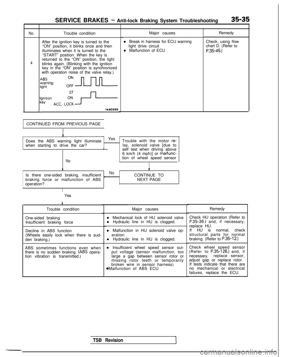
No.
4
rBSvarningght
I!Jnitlonkey
L
Trouble condition
After the ignition key is turned to the “ON” position, it blinks once and then
illuminates when it is turned to the “START” position. When the key is
returned to the “ON” position, the light
blinks again. (Blinking with the ignition
key in the “ON” position is synchronized
with operation noise of the valve relay.)
14A0593
CONTINUED FROM PREVIOUS PAGE Major causes
l Break in harness for ECU warning light drive circuit
l Malfunction of ECU
when starting to drive the car? Does the ABS warning light illuminate
Yes
Trouble with the motor
re-lay, solenoid valve [due to1self test when driving above
6 km/h (4 mph)] or malfunc-
Notion of wheel speed sensor
tt
Is there one-sided braking, insufficientNo
braking force or malfunction of ABS c
CONTINUE TO
NEXT PAGE
operation?
Yes
4
Trouble condition
One-sided braking Insufficient braking force
Decline in ABS function
(Wheels easily lock when there is sud-
den braking.)
ABS sometimes functions even when
there is no sudden braking.
(ABS opera-
tion vibration is transmitted.) Major causes
l Mechanical lock of HU solenoid valve
l Hydraulic line in HU is clogged.
l Malfunction in HU solenoid valve op- eration
l Hydraulic line in HU is clogged.
l Insufficient wheel speed sensor out- put voltage (sensor malfunction, too
large a gap between sensor rotor or
missing rotor teeth or temporarily
broken wire in sensor harness) 8 Malfunction of ABS ECU Remedy
Check, using flow
chart D. (Refer to
P.35-45.)
TSB Revision1
Remedy
Check HU operation (Refer to
P.35-36.) and, if necessary,
replace HU. If HU is normal, check
structural parts for normal
braking. (Refer to
P.35-12.)
Check wheel speed sensor
(Refer to P.35-126.) and, if
necessary, replace sensor,
adjust gap or replace rotor. If tests indicate that there are
no mechanical or electrical
failures, replace the ECU.
Page 1157 of 1273
35-36SERVICE BRAKES -Anti-lock Braking System Troubleshooting
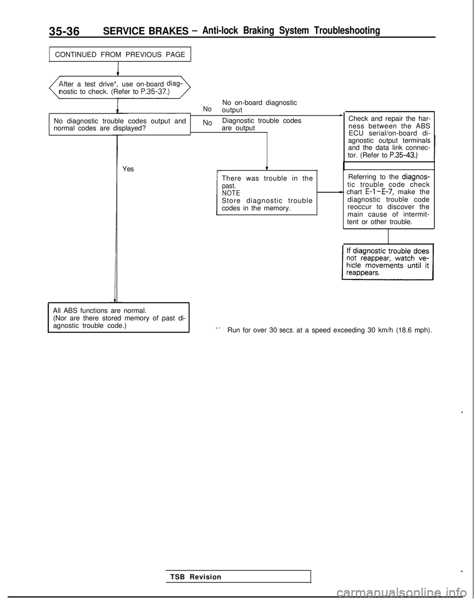
CONTINUED FROM PREVIOUS PAGE
I
fter a test drive*, use on-board
diag-
nostic to check. (Refer to P.35-37.)
No diagnostic trouble codes output and
normal codes are displayed?
NoNo on-board diagnostic
output l
NoDiagnostic trouble codes
are output
Yes Check and repair the har-
ness between the ABS
ECU serial/on-board di-
agnostic output terminals
and the data link connec-
tor. (Refer to
P.35-43.)
t
There was trouble in thepast.NOTEStore diagnostic trouble
codes in the memory. Referring to the diagnos-
tic trouble code check
- chart E-l-E-7, make the
diagnostic trouble code
reoccur to discover the
main cause of intermit-
tent or other trouble.
c
TSB Revision
All ABS functions are normal.
(Nor are there stored memory of past di-
agnostic trouble code.)
l .8Run for over 30 sets. at a speed exceeding 30 km/h (18.6 mph).
Page 1158 of 1273
SERVICE BRAKES - Anti-lock Braking System Troubleshooting35-37
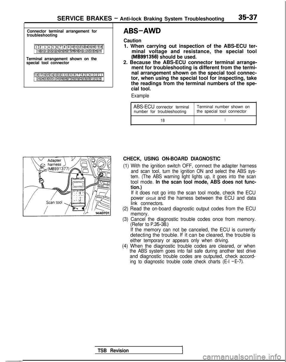
Connector terminal arrangement for
troubleshooting
[l I2 / 3 14 15 1617 16 I9[10~11~12(13~14~15(16~17[16j[lQ~20~21~22~23~24)25~26~27~28(29130~31~32~33~34~35~
Terminal arrangement shown on the
special tool connector
-.
TSB Revision
ABS-AWD
Caution
1. When carrying out inspection of the ABS-ECU ter-
minal voltage and resistance, the special tool
(MB991356) should be used.
2. Because the ABS-ECU connector terminal arrange- ment for troubleshooting is different from the termi-
nal arrangement shown on the special tool connec-
tor, when using the special tool for inspecting, take
the readings from the terminal numbers of the spe-
cial tool.
Example
ABS-ECU connector terminalTerminal number shown on
number for troubleshooting the special tool connector
181
CHECK, USING ON-BOARD DIAGNOSTIC
(1) With the ignition switch OFF, connect the adapter harness
and scan tool, turn the ignition ON and select the ABS sys-
tem. (The ABS warning light lights up, it goes into the scan
tool mode. In the scan tool mode, ABS does not func-
tion.)
If it does not go into the scan tool mode, check the ECU
power
circuit and the harness between the ECU and data
link connectors.
(2) Read the on-board diagnostic output codes from the ECU
memory.
(3) Cancel the diagnostic trouble codes once from memory. (Refer to
P.35-38.)
If the memory can not be canceled, the ECU is currently
detecting the trouble. If’it can be cleared, the trouble is
either temporary or appears only when driving.
(4) When the diagnostic trouble codes are cleared, or when
the ABS system goes into fail safe during another test drive
and diagnostic trouble codes are outputed, check accord-
ing to diagnostic trouble code check charts (E-l -E-7).
Page 1159 of 1273
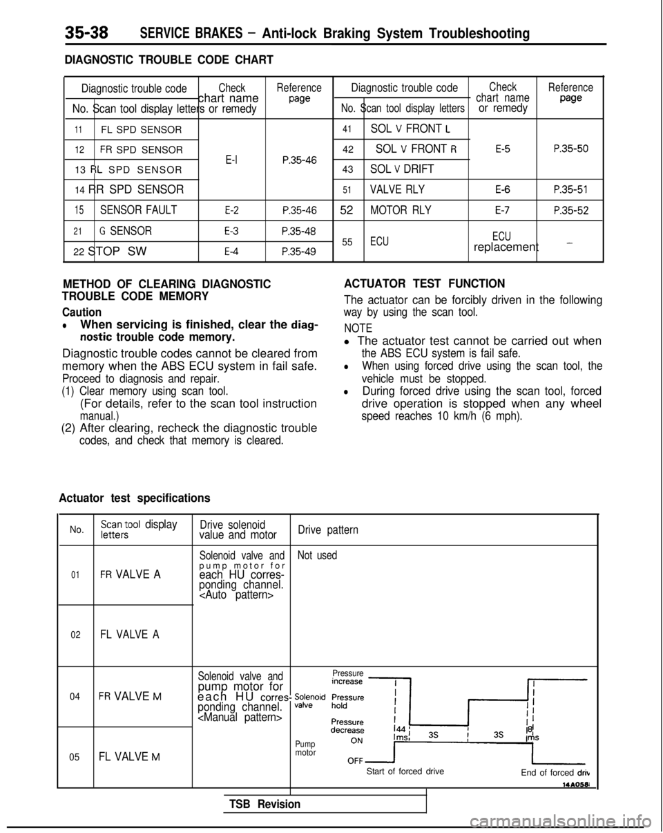
35-38SERVICE BRAKES - Anti-lock Braking System Troubleshooting
DIAGNOSTIC TROUBLE CODE CHART
Diagnostic trouble codeCheckReferenceDiagnostic trouble codeCheck
Reference
chart namewechart name
No. Scan tool display letters or remedyNo. Scan tool display lettersor remedypage
11FL SPD SENSOR
12FR SPD SENSOR
13
RL SPD SENSOR
14 RR SPD SENSOR
15SENSOR FAULT
21G SENSOR
22 STOP SW
E-l
E-2
E-3
E-4
41SOL V FRONT L
42SOL V FRONT RE-5P.35-50
P.35-4643SOL V DRIFT
51VALVE RLYE-6P.35-51
P.35-46 52MOTOR RLYE-7P.35-52
P.35-4855ECU ECUP.35-49replacement -
METHOD OF CLEARING DIAGNOSTIC
TROUBLE CODE MEMORY
Caution
lWhen servicing is finished, clear the diag-
nostic trouble code memory.
Diagnostic trouble codes cannot be cleared from
memory when the ABS ECU system in fail safe.
Proceed to diagnosis and repair.
(1) Clear memory using scan tool.
(For details, refer to the scan tool instruction
manual.)
(2) After clearing, recheck the diagnostic trouble
codes, and check that memory is cleared.
ACTUATOR TEST FUNCTION
The actuator can be forcibly driven in the following
way by using the scan tool.
NOTE
l The actuator test cannot be carried out when
the ABS ECU system is fail safe.
lWhen using forced drive using the scan tool, the
vehicle must be stopped.
lDuring forced drive using the scan tool, forced
drive operation is stopped when any wheel
speed reaches 10 km/h (6 mph).
Actuator test specifications
No.FGc$ool displayDrive solenoidvalue and motorDrive pattern
Solenoid valve and Not used
01FR VALVE Apump motor fo
r
each HU corres-ponding channel.
02FL VALVE A
Solenoid valve andPressure
04FR VALVE Mpump motor for
each HU corres- %Fwidponding channel.
05FL VALVE M
Pumpmotor
TSB Revision
Start of forced drive End of forced drib 14AO581
Page 1160 of 1273
![MITSUBISHI GALANT 1989 Service Repair Manual SERVICE BRAKES- Anti-lock Braking System Troubleshooting35-39
AABS warning light does not light at all.1
[Explanation][Hint]
When it does not light up at all, there is a strongIf other warning lighrs MITSUBISHI GALANT 1989 Service Repair Manual SERVICE BRAKES- Anti-lock Braking System Troubleshooting35-39
AABS warning light does not light at all.1
[Explanation][Hint]
When it does not light up at all, there is a strongIf other warning lighrs](/img/19/57312/w960_57312-1159.png)
SERVICE BRAKES- Anti-lock Braking System Troubleshooting35-39
AABS warning light does not light at all.1
[Explanation][Hint]
When it does not light up at all, there is a strongIf other warning lighrs do not light up either, fuse is
possibility that there is trouble with ABS warningprobably blown.
light or with power to the light.
MAIN FUSIBLELINK @of
LA
IGNITIONIGNITSWITCH (IG2)SWIT
-Tr-- -z
ABS POWERRELAY
‘IOct:I
1__--------I,7r
.I
:
,\c
AL1-f.
C.
dU
dr-3
gl”pzElzmq
4
4*I
21\5 ,&A27ABS ECU
;(IGI,
1234
7m5670
1
J/B
7
1COMBINATION
1METER
1r2
gizizgl
*
t
GNOGNDVV
*I:
Non-Turbo
TSB RevisionI