MITSUBISHI GALANT 1989 Service Repair Manual
Manufacturer: MITSUBISHI, Model Year: 1989, Model line: GALANT, Model: MITSUBISHI GALANT 1989Pages: 1273, PDF Size: 37.62 MB
Page 1171 of 1273
35-50SERVICE BRAKES - Anti-lock Braking System Troubleshooting
E-5
I I
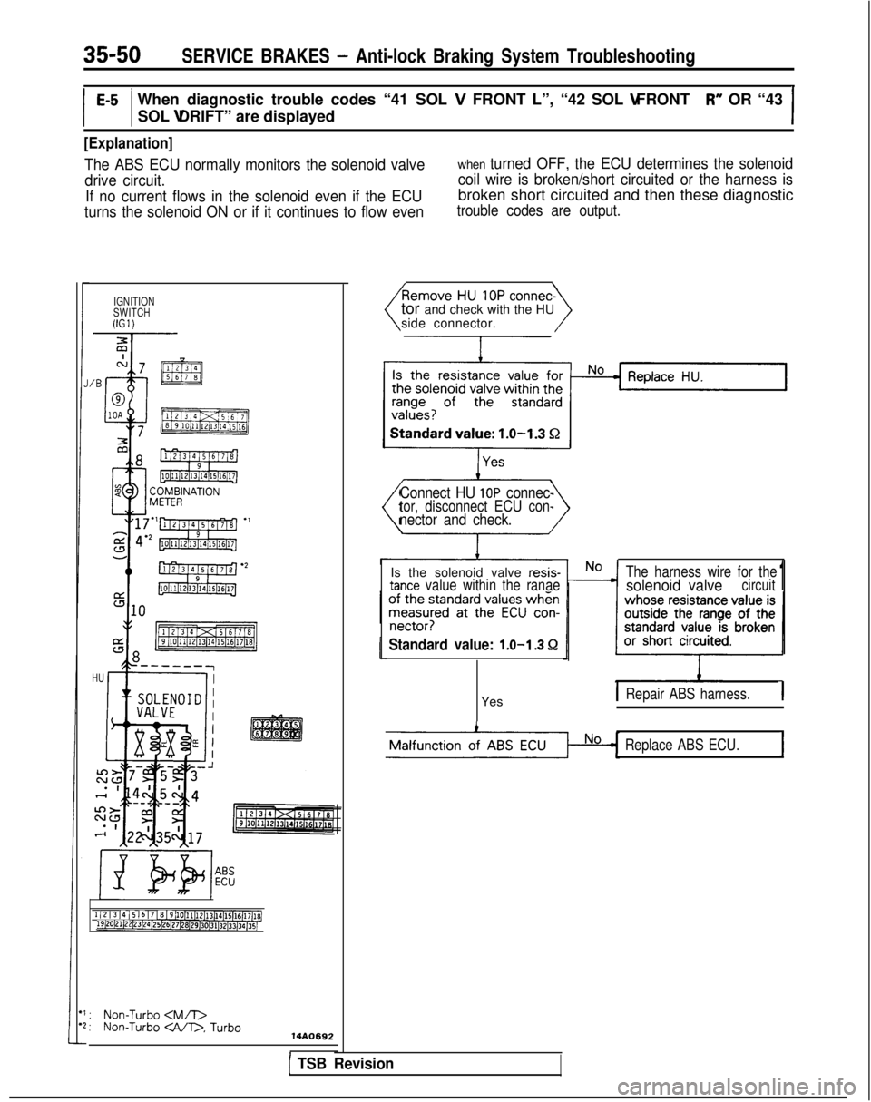
When diagnostic trouble codes “41 SOL V FRONT L”, “42 SOL V FRONT R” OR “43
SOL V DRIFT” are displayed
I
[Explanation]
The ABS ECU normally monitors the solenoid valve
drive circuit. If no current flows in the solenoid even if the ECU
turns the solenoid ON or if it continues to flow evenwhen turned OFF, the ECU determines the solenoid
coil wire is broken/short circuited or the harness is
broken short circuited and then these diagnostic
trouble codes are output.
IGNITION
SWITCH
llG1)
HU
1 / 2 / 3 14 15 16 I 7 ~8~9h0~11~12~13~14~15[16[17@,19bO~21i22~3~24~25)26~27~28~29~30)31$2~33)34[35j
:Non-Turbo
side connector.
Connect HU IOP connec-tor, disconnect ECU con-nector and check.
Is the solenoid valve resis-tance value within the ranae
The harness wire for thesolenoid valvecircuit1
nectar?
Standard value: 1.0-l .3 Q
YesIRepair ABS harness.1
Replace ABS ECU.1
I1 TSB Revision
Page 1172 of 1273
![MITSUBISHI GALANT 1989 Service Repair Manual SERVICE BRAKES - Anti-lock Braking System Troubleshooting35-51
E-5When diagnostic trouble code “51 VALVE RLY” is displayed
[Explanation]
When the ignition switch is turned ON, the ABS
ECU switches MITSUBISHI GALANT 1989 Service Repair Manual SERVICE BRAKES - Anti-lock Braking System Troubleshooting35-51
E-5When diagnostic trouble code “51 VALVE RLY” is displayed
[Explanation]
When the ignition switch is turned ON, the ABS
ECU switches](/img/19/57312/w960_57312-1171.png)
SERVICE BRAKES - Anti-lock Braking System Troubleshooting35-51
E-5When diagnostic trouble code “51 VALVE RLY” is displayed
[Explanation]
When the ignition switch is turned ON, the ABS
ECU switches the valve relay OFF and ON for an
initial check, compares the voltage of the signal to
the valve relay and valve power monitor line voltage
to check whether the valverelay operationis
normal. In addition, normally it monitors whether or
not there is power in the valve power monitor line
since the valve relay is normally ON. Then, if the
supply of power to the valve power monitor line is
interrupted, this diagnostic trouble code will output.
MAIN FUSIBLE$tW&N
LINK @I(IGl)
gEli!z$; lf*x**
IT
510
IU-412 &-,8
ABS ECU
: Non-Turbo . Turbo: Non-Turbo
When the valve relay i
s
checked, are the following
conditions found?No. 85-No. 86:resistance
value 60-120 52No.30-No.87a: continuity
No. 30-No. 87: No continui-
When battery voltage is ap- plied between terminals
No. 86 and No. 85 grounded.
No.30-No.87: continuity
No. 30-No. 87a: no continui-
t
y
remove the HU connec-
\/
I With
the
ignition key “ON”
,
No c HU power harness wire is
does the voltage betweenbroken?the connector terminal No.
12 and ground indicate bat- tery voltage? I
IRepair harness.
YesIIIbI\I
Does resistance between
body connector termina
l
No. 2 and terminal No. 27 in-
dicate
60-120 ohm?
IYes
Is there continuity between
body connector terminal No.
22 and ground? Repair harness.
ABS ECU malfunction Replace ABS ECU.
1 TSB Revision1
Page 1173 of 1273
![MITSUBISHI GALANT 1989 Service Repair Manual 35-52SERVICE BRAKES - Anti-lock Braking System Troubleshooting
E-7When diagnostic trouble code “52 MOTOR RLY” is displayedI
[Explanation][Hint]
The ABS ECU outputs this diagnostic trouble code for MITSUBISHI GALANT 1989 Service Repair Manual 35-52SERVICE BRAKES - Anti-lock Braking System Troubleshooting
E-7When diagnostic trouble code “52 MOTOR RLY” is displayedI
[Explanation][Hint]
The ABS ECU outputs this diagnostic trouble code for](/img/19/57312/w960_57312-1172.png)
35-52SERVICE BRAKES - Anti-lock Braking System Troubleshooting
E-7When diagnostic trouble code “52 MOTOR RLY” is displayedI
[Explanation][Hint]
The ABS ECU outputs this diagnostic trouble code forIf there is motor operation noise when wheel speed
the motor relay and motor in the following cases. exceeds Gkm/h
(4mph) when starting up after the
l When the motor relay does not function engine is started, or when there is forced scan tool
l When there is trouble with the motor
itself and itdrive, there is a broken or short circuited motor
does not revolve monitor wire.
l When there is trouble with the motor itself and it
the motor does not revolve
l When the motor continues to revolve Yes
Broken wire or short cir-
-Inoise when wheel
speedcuit in motor monitor line
MAIN FUSIBLE
LINK @&
1 j 2 I3 I4 I5 I6 I 7 18 I9 l10l11112113114115116l17 1819p0~1122~3~24l2S~26I27(2~29130131l32l33l3~~3~
(Remove the motor relay>
r
l
-
\
/4~
Remove the motor relay and -check resistance values.No c Motor relay malfunction
No. 85-No. 86:resistance4
value 30-60
QNo.30-No.87: no continui-
Replace motor relay.
t
y
Battery voltage is applied on
terminals No.86
and
No.85groundedNo.30-No.87: continuity 1Yes
Is pump motor ground con-
No
netted normally?
Connect ground wire.
lYes
<
Install motor relay and
move HU connector.
Does voltage between body
connector terminal 11 and
No ) Broken wire in pum
p
ground indicate battery vol- motor power circuit
tage?
4
Yes Repair the harness.I
tor and
remove theECU
Is resistance between body - No - Malfunction of harness
connector terminal No. 2 andNo No.26
30-60 ohms? between HU and ECUI
4 Yes.
Repair harness.II
ABS ECU malfunction
Replace ABS ECU.I
TSB Revision
Page 1174 of 1273
SERVICE BRAKES - Service Adjustment Procedures35-53
switch
switch
c/ 14F516
Pedal
Idown /
\ \
F14517
TSB Revision
F14518
SERVICE ADJUSTMENT PROCEDURES
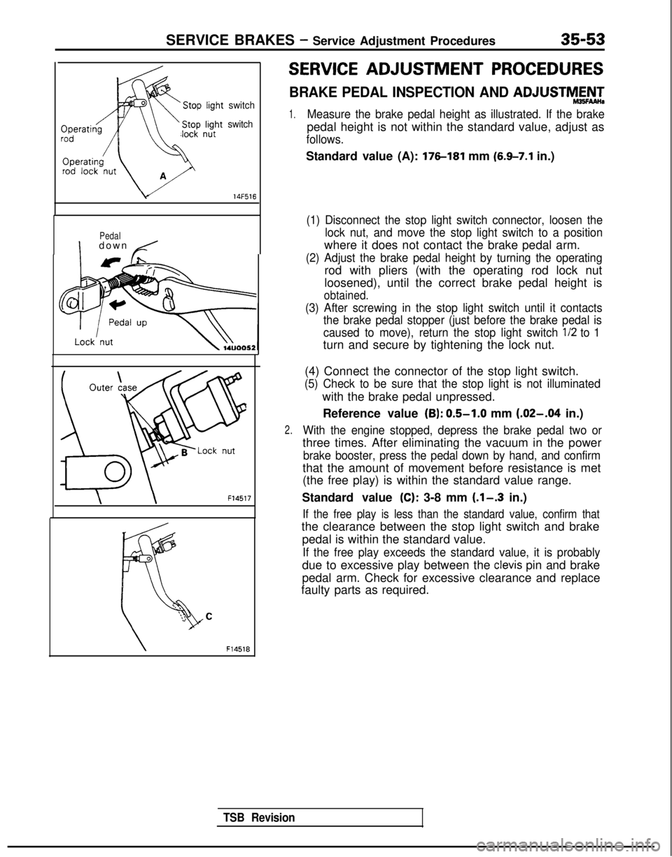
BRAKE PEDAL INSPECTION AND ADJUSTMAN-
1.Measure the brake pedal height as illustrated. If the brake
pedal height is not within the standard value, adjust as
follows.
Standard value (A): 176-181 mm (6.9-7.1 in.)
(1) Disconnect the stop light switch connector, loosen the
lock nut, and move the stop light switch to a position
where it does not contact the brake pedal arm.
(2) Adjust the brake pedal height by turning the operating
rod with pliers (with the operating rod lock nut
loosened), until the correct brake pedal height is
obtained.
(3) After screwing in the stop light switch until it contactsthe brake pedal stopper (just before the brake pedal is
caused to move), return the stop light switch l/2
to 1
turn and secure by tightening the lock nut.
2.
(4) Connect the connector of the stop light switch.
(5) Check to be sure that the stop light is not illuminated
with the brake pedal unpressed.
Reference value
(B): 0.5-1.0 mm (.02-.04 in.)
With the engine stopped, depress the brake pedal two or
three times. After eliminating the vacuum in the power
brake booster, press the pedal down by hand, and confirm
that the amount of movement before resistance is met
(the free play) is within the standard value range.
Standard value
(C): 3-8 mm (.l-.3 in.)
If the free play is less than the standard value, confirm that
the clearance between the stop light switch and brake pedal is within the standard value.
If the free play exceeds the standard value, it is probably
due to excessive play between the clevis pin and brake
pedal arm. Check for excessive clearance and replace
faulty parts as required.
Page 1175 of 1273
35-54SERVICE BRAKES - Service Adjustment Procedures
F14519
14UOO61
When engine isstopped
No good
0
w
\/‘14UOO62z;redengine
is
14UOO60 ,3.
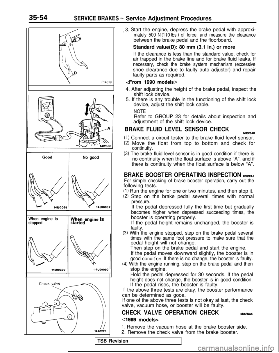
Start the engine, depress the brake pedal with approxi-
mately 500 N (110 Ibs.) of force, and measure the clearance
between the brake pedal and the floorboard.
Standard value(D): 80 mm (3.1 in.) or more
If the clearance is less than the standard value, check for
air trapped in the brake line and for brake fluid leaks. If
necessary, check the brake system mechanism (excessive
shoe clearance due to faulty auto adjuster) and repair
faulty parts as required.
4. After adjusting the height of the brake pedal, inspect the shift lock device.
5. If there is any trouble in the functioning of the shift lock device, adjust the shift lock cable.
NOTE
Refer to GROUP 23 for details about inspection and
adjustment of the shift lock device.
BRAKE FLUID LEVEL SENSOR CHECKM35F6A6
(1) Connect a circuit tester to the brake fluid level sensor.
(2) Move the float from top to bottom and check for
continuity.
(3) The brake fluid level sensor is in good condition if there is
no continuity when the float surface is above “A”, and if
there is continuity when the float surface is below “A”.
BRAKE BOOSTER OPERATING INSPECTION MlKcAJ
For simple checking of brake booster operation, carry out the
following tests.
(1) Run the engine for one or two minutes, and then stop it.
(2) Step on the brake pedal several’ times with normal
pressure.
If the pedal depressed fully the first time but gradually
becomes higher when depressed succeeding times, the
booster is operating properly.
If the pedal height remains unchanged, the booster is
faulty.
(3) With the engine stopped, step on the brake pedal several
(4
If
times with the same foot pressure to make sure that the
pedal height will not change.
Then step on the brake pedal and start the engine.
If the pedal moves downward slightly, the booster is in
good condit’on. If there is no change, the booster is faulty.
.) With the engine running, step on the brake pedal and then
stop the engine.
Hold the pedal depressed for 30 seconds. If the pedal
height does not change, the booster is in good condition.
If the pedal rises, the booster is faulty.
the above three tests are okay, the booster performance
can be determined as gooa.
If one of the above three tests is not okay at last, the check
valve, vacuum hose, or booster will be faulty.
CHECK VALVE OPERATION CHECKM3!3FNAK
cl989 models>
1. Remove the vacuum hose at the brake booster side.
2. Remove the check valve from the brake booster.
TSB Revision
Page 1176 of 1273
SERVICE BRAKES - Service Adjustment Procedures35-55
Valve .,Spring
3rake)oostelside
14AO358
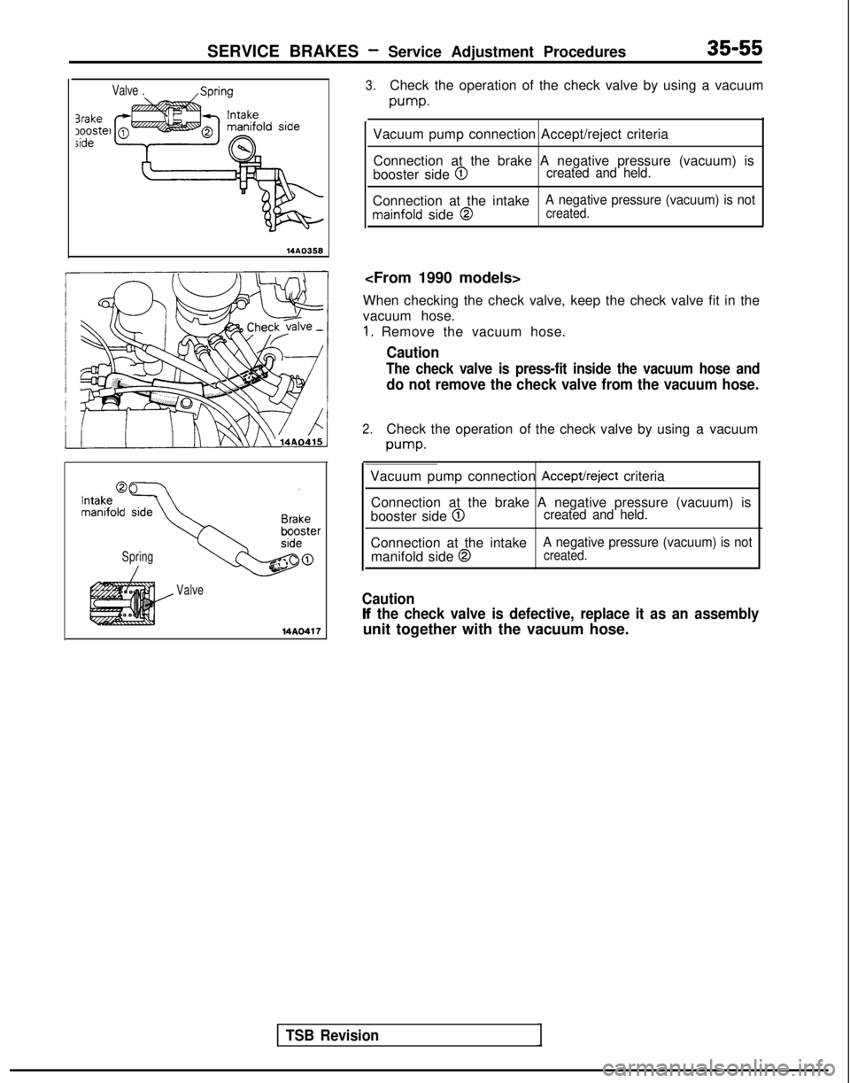
3.Check the operation of the check valve by using a vacuum
pump.
Vacuum pump connection Accept/reject criteria
Connection at the brake A negative pressure (vacuum) is
booster side
@Icreated and held.
Connection at the intakemainfold side @
A negative pressure (vacuum) is notcreated.
When checking the check valve, keep the check valve fit in the
vacuum hose.
1. Remove the vacuum hose.
Caution
The check valve is press-fit inside the vacuum hose and
do not remove the check valve from the vacuum hose.
2.Check the operation of the check valve by using a vacuum
pump.
Spring
Valve
14A0417
TSB Revision1
Vacuum pump connection Accept/reject criteria
Connection at the brake A negative pressure (vacuum) is
booster side
@created and held.
Connection at the intake manifold side @
A negative pressure (vacuum) is notcreated.
Caution
If the check valve is defective, replace it as an assembly
unit together with the vacuum hose.
Page 1177 of 1273
35-56SERVICE BRAKES - Service Adiustment Procedures
Pressurew-wPressure
Proportioning valve momi
,.,’
Split point ,,s*”
I’
I’
,’Outpur,’
I’
pressure
izl
Input pressure
14uoo55
PROPORTIONING VALVE FUNCTION TEST M~KKAK
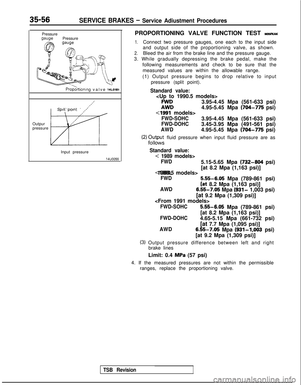
1.Connect two pressure gauges, one each to the input side
and output side of the proportioning valve, as shown.
2.Bleed the air from the brake line and the pressure gauge.
3. While gradually depressing the brake pedal, make the following measurements and check to be sure that themeasured values are within the allowable range.
(1) Output pressure begins to drop relative to input pressure (split point).
Standard value:
ii:
3.95-4.45 Mpa (561-633 psi)
4.95-5.45 Mpa
(704-775 psi)
cl991 models>
FWD-SOHC3.95-4.45 Mpa (561-633 psi)
FWD-DOHC3.45-3.95 Mpa (491-561 psi)
AWD4.95-5.45 Mpa (704-775 psi)
(2) Ou;x~; fluid pressure when input fluid pressure are as
Standard value:
< 1989 models>
FWD5.15-5.65 Mpa (732-804 psi)
[at 8.2 Mpa (1,163 psi)] <1990, 1990.5 models>
FWD
5.55-6.05
Mpa (789-861 psi)
[at 8.2 Mpa (1,163 psi)]
AWD 6.55-7.05
Mpa (931- 1,003 psi)
[at 9.2 Mpa (1,309 psi)]
FWD-SOHC 5.55-6.05
Mpa (789-861 psi)
[at 8.2 Mpa (1,163 psi)]
FWD-DOHC4.65-5.15 Mpa (661-732 psi)
[at 7.7 Mpa (1,095 psi)]
AWD6.55-7.05 Mpa (931-1,003
psi)
[at 9.2 Mpa (1,309 psi)]
(3) Output pressure difference between left and right brake lines
Limit: 0.4
MPa (57 psi)
4. If the measured pressures are not within the permissible ranges, replace the proportioning valve.
TSB Revision
Page 1178 of 1273
SERVICE, BRAKES - Service Adjustment Procedures35-57
4
1
2314AQ456
FWD
Delay valve L
flc ’
-c
i1
L
3
14AO4l
mit
14RD120
AWD
51
6 2414AO4E
BLEEDING
Because the master cylinder employed is the type without the
check valve, air should be bled from the master cylinder by
following the procedures described below (if there is no brake
fluid in the master cylinder).
(1) Disconnect the brake tube from the master cylinder.
(2) Two persons’ should conduct the air bleeding, one person
slowly depressing the brake pedal and holding the pedal
depressed.
(3) In this condition, the other person should use a finger to close the outlet part of the master cylinder, and then the
first person should release the brake pedal.
(4) Steps (2) and (3) should be repeated three or four times, and then the master cylinder should be filled with brake
fluid to the specified level.
I(]OTE
The air is completely bled from the master cylinder by
steps (1) to (4).
(5) Connect the brake tube to the master cylinder.
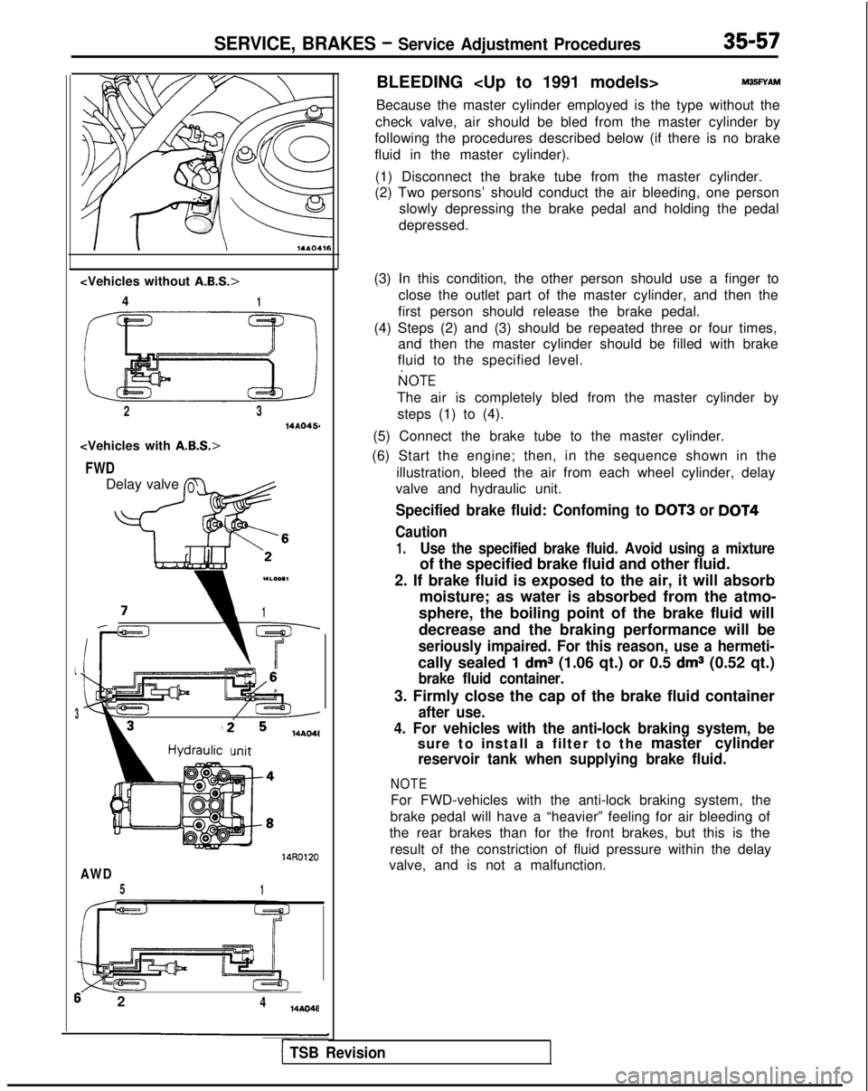
(6) Start the engine; then, in the sequence shown in the illustration, bleed the air from each wheel cylinder, delay
valve and hydraulic unit.
Specified brake fluid: Confoming to DOT3 or DOT4
Caution
1.Use the specified brake fluid. Avoid using a mixture
of the specified brake fluid and other fluid.
2. If brake fluid is exposed to the air, it will absorb moisture; as water is absorbed from the atmo-
sphere, the boiling point of the brake fluid will
decrease and the braking performance will be
seriously impaired. For this reason, use a hermeti-
cally sealed 1 dms (1.06 qt.) or 0.5 dms (0.52 qt.)
brake fluid container.
3. Firmly close the cap of the brake fluid container
after use.
4. For vehicles with the anti-lock braking system, be
sure to install a filter to the master cylinder
reservoir tank when supplying brake fluid.
NOTE
For FWD-vehicles with the anti-lock braking system, the
brake pedal will have a “heavier” feeling for air bleeding of
the rear brakes than for the front brakes, but this is the
result of the constriction of fluid pressure within the delay
valve, and is not a malfunction.
1 TSB Revision
Page 1179 of 1273
35-58SERVICE BRAKES - Service Adjustment Procedures
14*ooat
Delay
valve Bleeder screw
(for the left rear brakes)i
Bleeder screw
I.LOO.1lheck valve bolt20-25 Nm (14-18 ft.lbs.)
ORDINARY AIR-BLEEDING PROCEDURES
(1) Depress the brake pedal several times until resistance is
felt; then, with the pedal depressed, loosen the bleederscrew
113 to l/2 turn and then tighten it before the fluid
pressure is all gone.
(2) Release the brake pedal. Repeat this procedure until there
are no more air bubbles in the brake fluid.
AIR BLEEDING FROM DELAY VALVE
4WD-ABS>
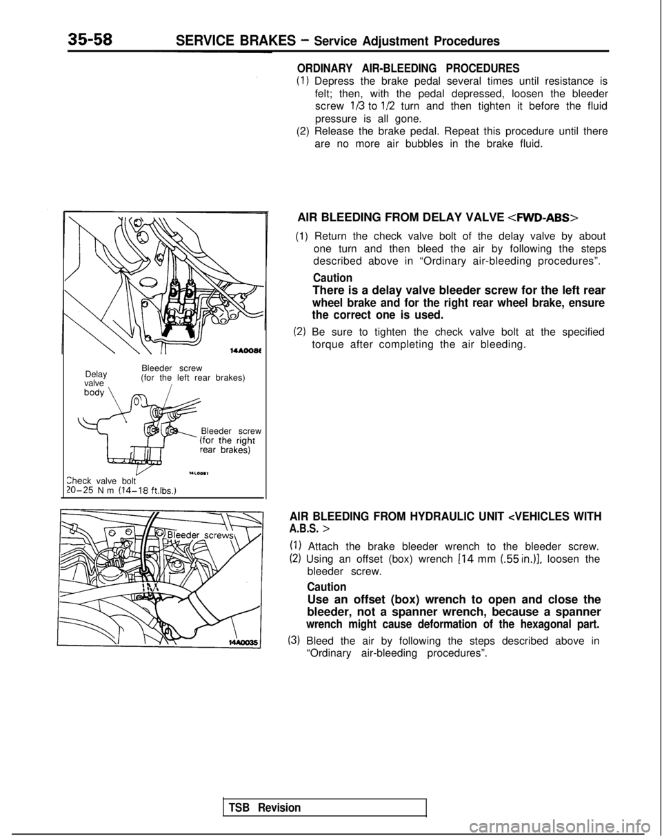
(1) Return the check valve bolt of the delay valve by about one turn and then bleed the air by following the steps
described above in “Ordinary air-bleeding procedures”.
Caution
There is a delay valve bleeder screw for the left rear
wheel brake and for the right rear wheel brake, ensure
the correct one is used.
(2) Be sure to tighten the check valve bolt at the specified
torque after completing the air bleeding.
AIR BLEEDING FROM HYDRAULIC UNIT
(1) Attach the brake bleeder wrench to the bleeder screw.
(2) Using an offset (box) wrench 114 mm (55 in.)], loosen the
bleeder screw.
Caution
Use an offset (box) wrench to open and close the
bleeder, not a spanner wrench, because a spanner
wrench might cause deformation of the hexagonal part.
(3) Bleed the air by following the steps described above in “Ordinary air-bleeding procedures”.
TSB Revision
Page 1180 of 1273
SERVICE BRAKES - Service Adjustment Procedures35-59
14 LO169
FRONT DISC BRAKE PAD CHECK AND REPLACE-
MENT
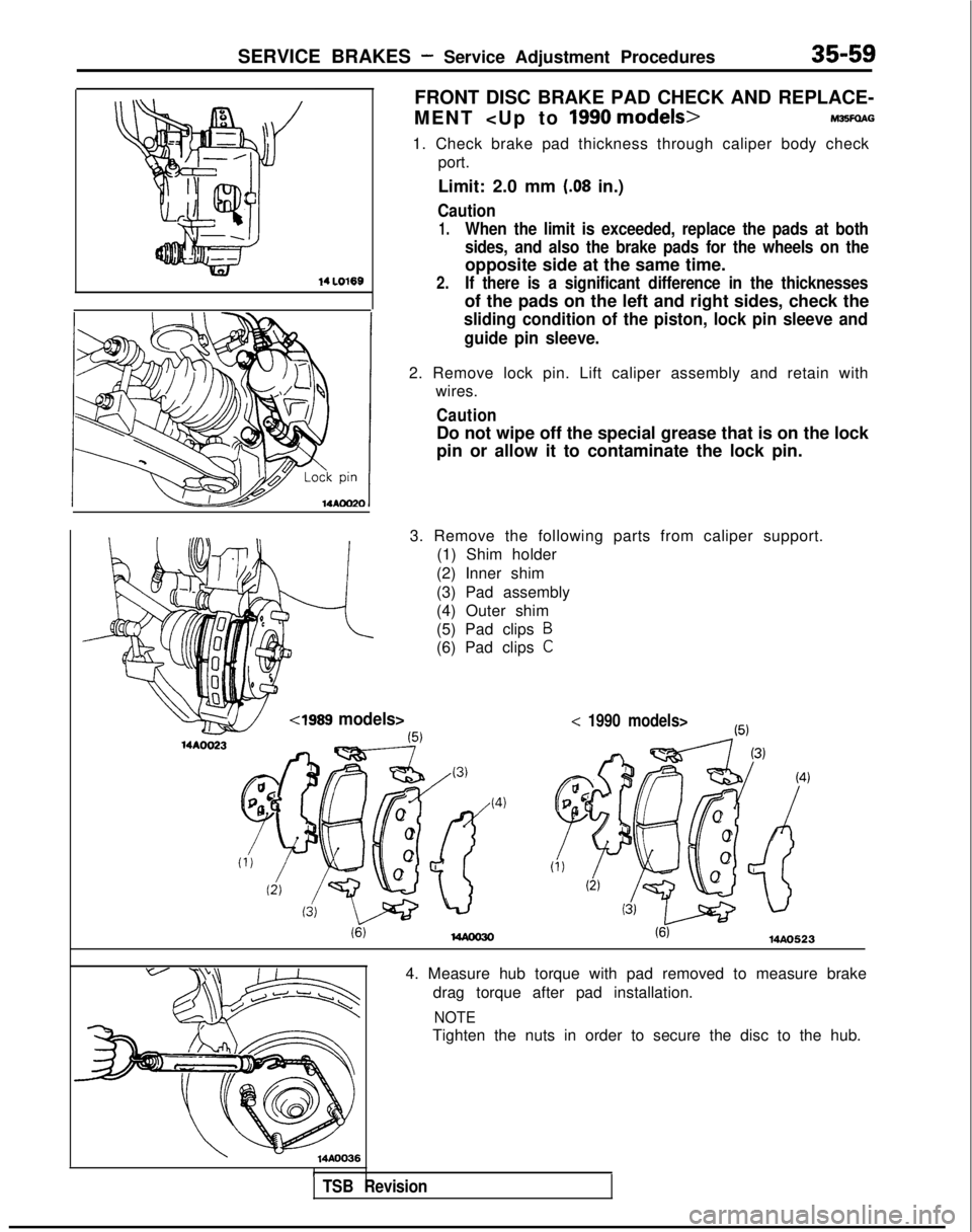
1. Check brake pad thickness through caliper body check port.
Limit: 2.0 mm
(.08 in.)
Caution
1.When the limit is exceeded, replace the pads at both
sides, and also the brake pads for the wheels on the
opposite side at the same time.
2.If there is a significant difference in the thicknesses
of the pads on the left and right sides, check the
sliding condition of the piston, lock pin sleeve and
guide pin sleeve.
2. Remove lock pin. Lift caliper assembly and retain with wires.
Caution
Do not wipe off the special grease that is on the lock
pin or allow it to contaminate the lock pin.
3. Remove the following parts from caliper support. (1) Shim holder
(2) Inner shim
(3) Pad assembly
(4) Outer shim
(5) Pad clips
B
(6) Pad clips C
Cl989 models>< 1990 models>
(6)MAO523
14AOO361
4. Measure hub torque with pad removed to measure brake drag torque after pad installation.
NOTE
Tighten the nuts in order to secure the disc to the hub.
TSB Revision