MITSUBISHI GALANT 1989 Service Repair Manual
Manufacturer: MITSUBISHI, Model Year: 1989, Model line: GALANT, Model: MITSUBISHI GALANT 1989Pages: 1273, PDF Size: 37.62 MB
Page 1211 of 1273
35-90SERVICE
BRAKES - Brake Line
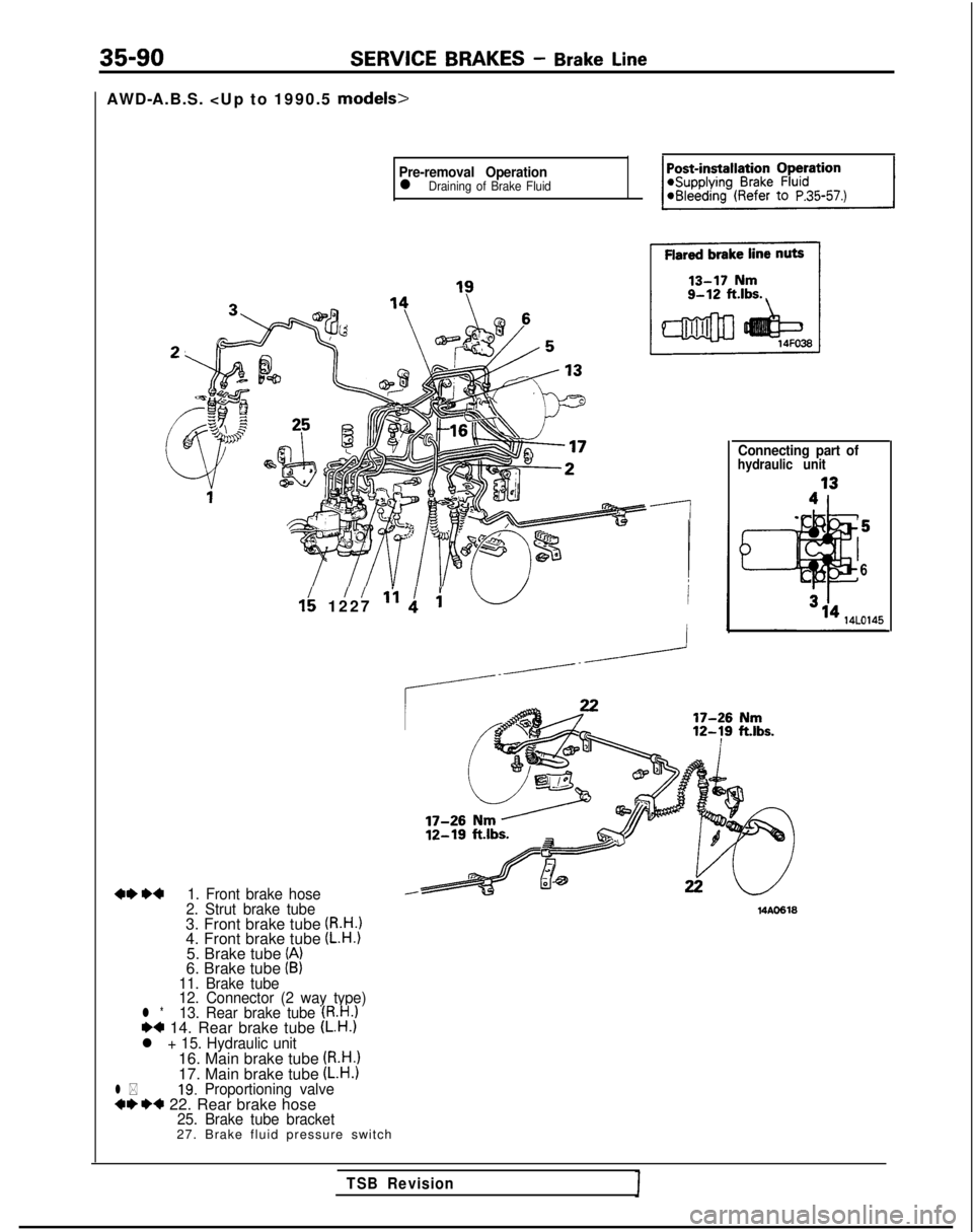
AWD-A.B.S.
Pre-removal Operationl Draining of Brake Fluid
1: 1227‘f Iid i
+*W1. Front brake hose
2. Strut brake tube
3. Front brake tube (R.H.14. Front brake tube (L.H.)5. Brake tube (A)6. Brake tube (B)11. Brake tube
12. Connector (2 way type)
l *13. Rear brake tube (R.H.1+4 14. Rear brake tube (L.H.1l + 15. Hydraulic unit16. Main brake tube (R.H.)17. Main brake tube (L.H.)l *19. Proportioning valve++I)+ 22. Rear brake hose25. Brake tube bracket27. Brake fluid pressure switch
Connecting part ofhydraulic unit
6 14AO618
TSB Revision
Page 1212 of 1273
SERVICE BRAKES - Brake Line
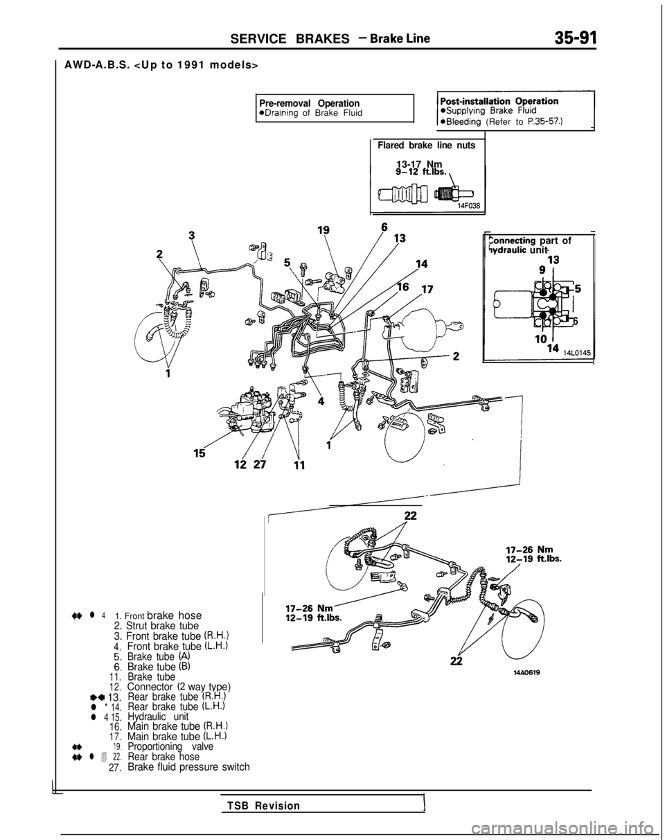
AWD-A.B.S.
Pre-removal OperationeDraining of Brake Fluid@Bleeding (Refer to P.35-57.)
Flared brake line nuts
13-17 Nm
Zonnecting part oflydraulic unit
6
+e l
41. Front brake hose2. Strut brake tube
3. Front brake tube (R.H.!4.
::11.
12.
I)* 13.l * 14.
l 4 15.
16.17.
:: l 4 ii:
27.
Front brake tube (L.H.1Brake tube (A)Brake tube (B)Brake tubeConnector (2 way type)Rear brake tube (R.H.)Rear brake tube (L.H.)Hydraulic unitMain brake tube (R.H.)Main brake tube (L.H.)Proportioning valve
Rear brake hose
Brake fluid pressure switch 14AO619
TSB RevisionI
Page 1213 of 1273
35-92SERVICE BRAKES - Brake Line
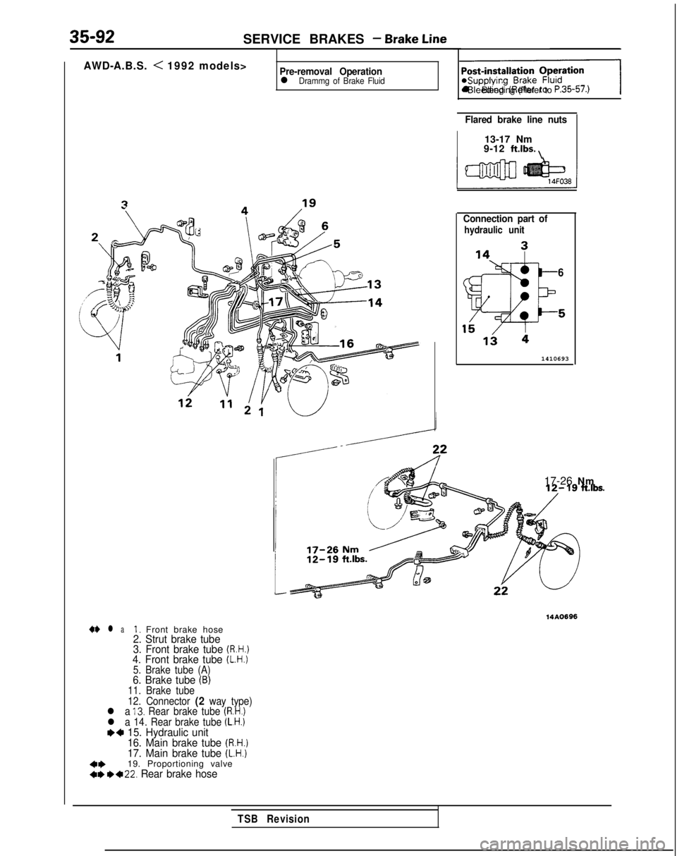
AWD-A.B.S. < 1992 models>Pre-removal Operationl Drammg of Brake Fluid-1
l Bleeding (Refer to P.35-57.)
Flared brake line nuts
13-17 Nm
9-12 ft.lbs. \
Connection part of
hydraulic unit
6
1410693
17-26 Nm
14AO696
a+ l aI. Front brake hose2. Strut brake tube
3. Front brake tube (R.H.)4. Front brake tube (L.H.)5. Brake tube (A)6. Brake tube (B)11. Brake tube
12. Connector (2 way type)l a 13. Rear brake tube (R.H.)l a 14. Rear brake tube (L.H.)~~ 15. Hydraulic unit
16. Main brake tube (R.H.)17. Main brake tube (L.H.)
++19. Proportioning valve+,*+22. Rear brake hose
TSB Revision
Page 1214 of 1273
SERVICE BRAKES - Brake Line35-93
Brake hose
14w59314uooG7
SERVICE POINTS OF REMOVALM35KBAla
1. REMOVAL OF FRONT BRAKE HOSE/22. REAR BRAKE
HOSE
(1) Holding the lock nut on the brake hose side, loosen
the flared brake line nut.
(2) Pull off the brake hose clip and remove the brake hose from the bracket.
19. REMOVAL OF PROPORTIONING
VALVE/24. DELAY
VALVE
Do not disassemble the proportioning valve and delay
valve because its performance depends on the set load of
the spring.
INSPECTION
M35KCAA
l Check the brake tubes for cracks, crimps and corrosion.
l Check the brake hoses for cracks, damage and leakage.
0Check the flared brake line nuts for damage and leakage.
SERVICE POINTS OF INSTALLATION
M35KDAGa
15.CONNECTlON OF TUBE AND HOSE TO HYDRAULIC
UNIT
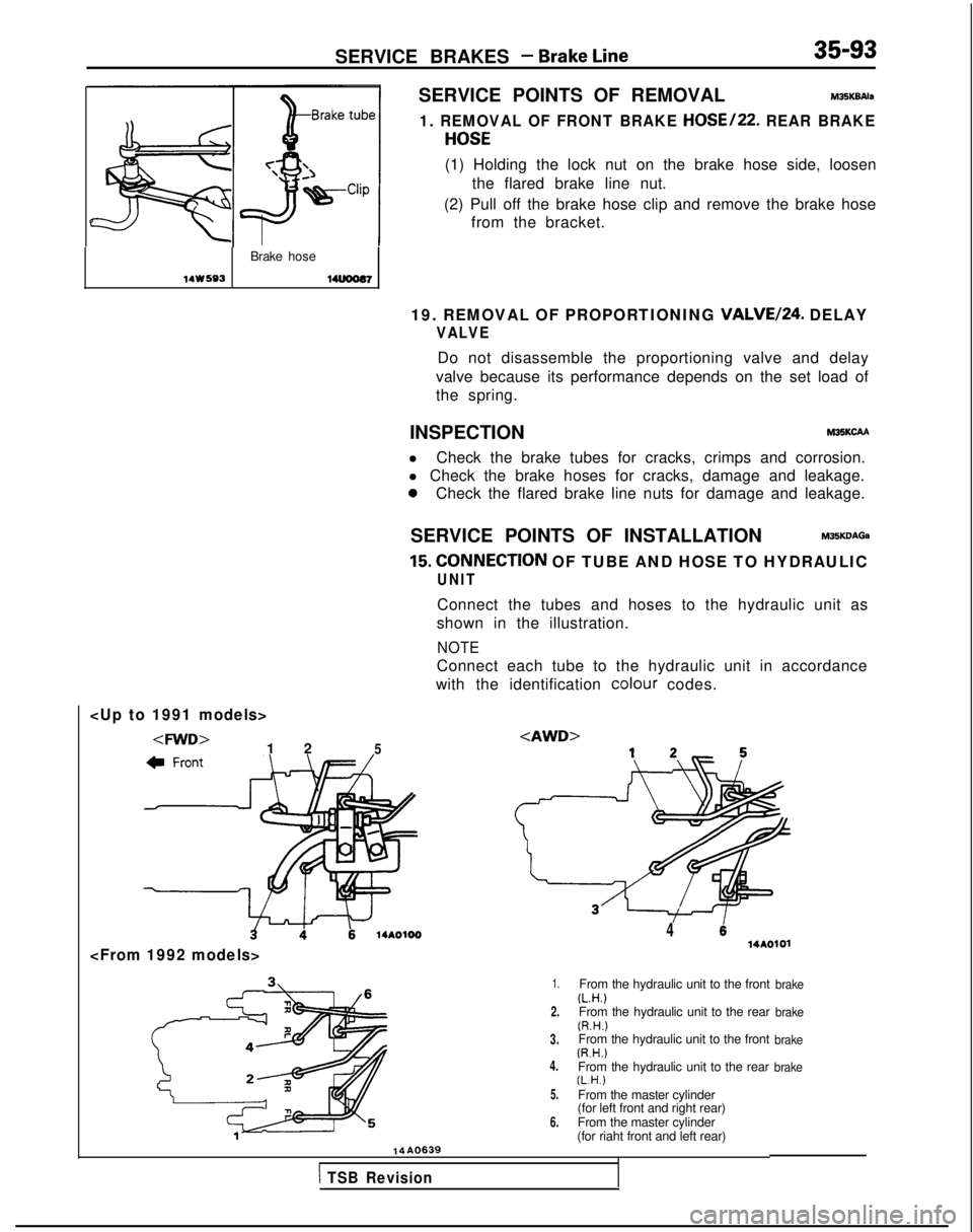
Connect the tubes and hoses to the hydraulic unit as
shown in the illustration.
NOTE
Connect each tube to the hydraulic unit in accordance
with the identification colour
codes.
414AOlOl
1.
2.
3.
4.
5.
6.
From the hydraulic unit to the front(L.H.)From the hydraulic unit to the rear(R.H.)From the hydraulic unit to the front(R.H.)From the hydraulic unit to the rear(L.H.)From the master cylinder
(for left front and right rear)
From the master cylinder
(for riaht front and left rear)
brake
brake
brake
brake
14A0639
1 TSB Revision
Page 1215 of 1273
35-94SERVICE BRAKES -Brake Line/Front Disc Brake14./13.
CONNECTION OF BRAKE TUBE
Arrange the brake tubes so that there is no
contac? with
edges, weld “beats”, etc., and make the connections
securely.
22. INSTALLATION OF REAR BRAKE HOSE/l. FRONT
BRAKE HOSE
Install the brake hoses without twisting them.
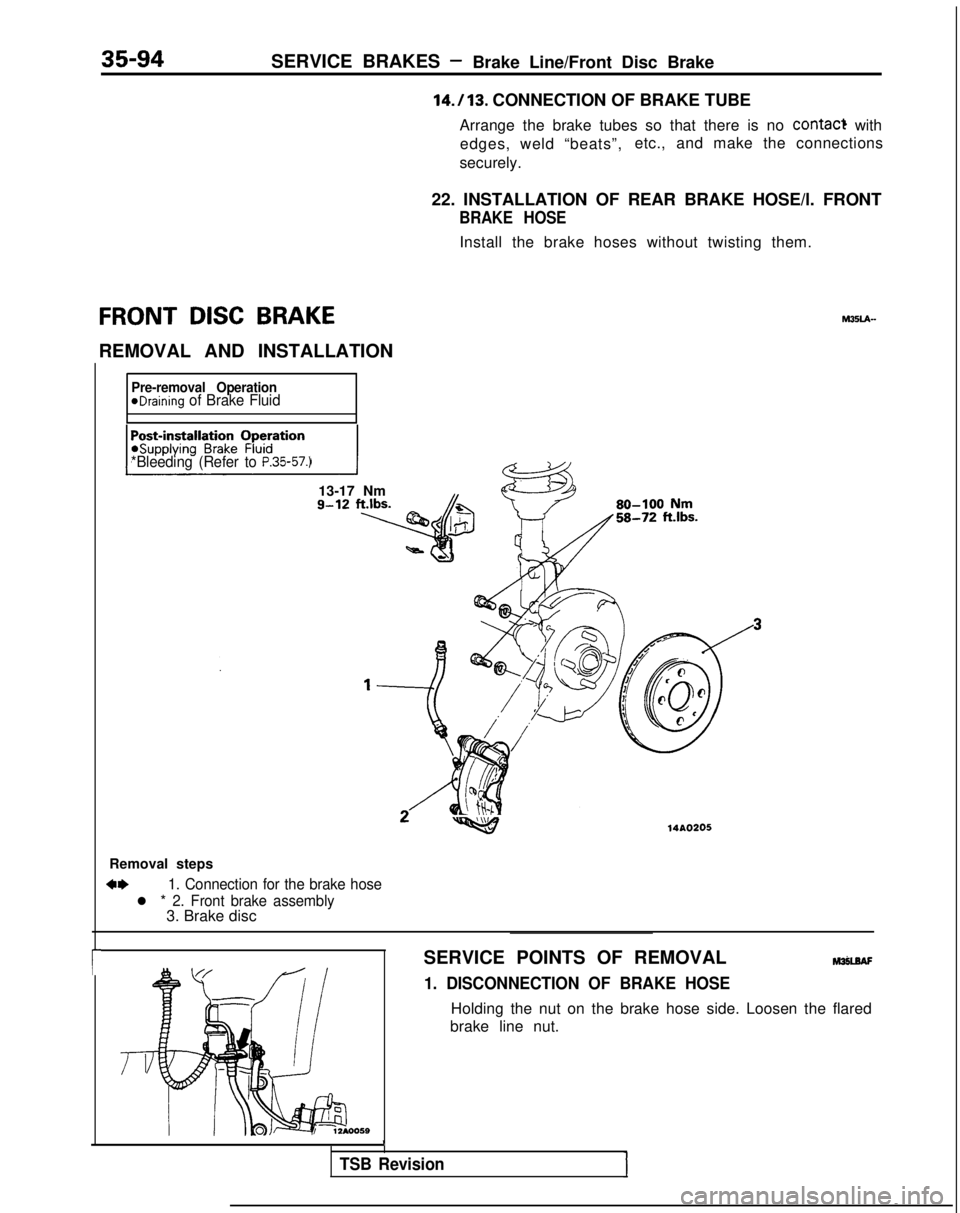
FRONT DISC BRAKE
REMOVAL AND INSTALLATION
r
Pre-removal OperationeDraining of Brake Fluid
*Bleeding (Refer to
P.35-57.)
13-17 Nmg-12 ft.lbs.
Removal steps
c*1. Connection for the brake hose
l * 2. Front brake assembly3. Brake disc
-w14AO205 M35LA-
SERVICE POINTS OF REMOVAL
hlanAF
1. DISCONNECTION OF BRAKE HOSE
Holding the nut on the brake hose side. Loosen the flared
brake line nut.
1
TSB Revision
Page 1216 of 1273
SERVICE BRAKES - Front Disc Brake35-95
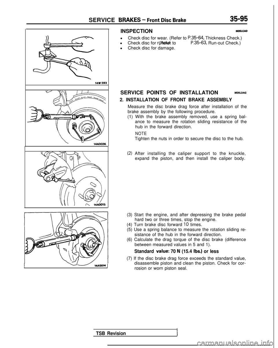
INSPECTIONM35LcAD
l
Check disc for wear. (Refer to P.35-64, Thickness Check.)
l Check disc for runout. (Refer to
P.35-63, Run-out Check.)
l Check disc for damage.
14w 593
\ ”14AOO36
SERVICE POINTS OF INSTALLATIONM35LDAG
2. INSTALLATION OF FRONT BRAKE ASSEMBLY
Measure the disc brake drag force after installation of the
brake assembly by the following procedure.
(1) With the brake assembly removed, use a spring bal- ance to measure the rotation sliding resistance of the
hub in the forward direction.
NOTE
Tighten the nuts in order to secure the disc to the hub.
(2) After installing the caliper support to the knuckle, expand the piston, and then install the caliper body.
I14AOOl4 1
(3) Start the engine, and after depressing the brake pedal hard two or three times, stop the engine.
(4) Turn brake disc forward
10 times.
(5) Use a spring balance to measure the rotation sliding re-
sistance of the hub in the forward direction.
(6) Calculate the drag torque of the disc brake (difference
between measured values in 5 and 1).
Standard value: 70 N (15.4 Ibs.) or less
(7) If the disc brake drag force exceeds the standard value,disassemble piston and clean the piston. Check for cor-
rosion or worn piston seal.
TSB RevisionI
Page 1217 of 1273
35-96SERVICE BRAKES - Front Disc Brake
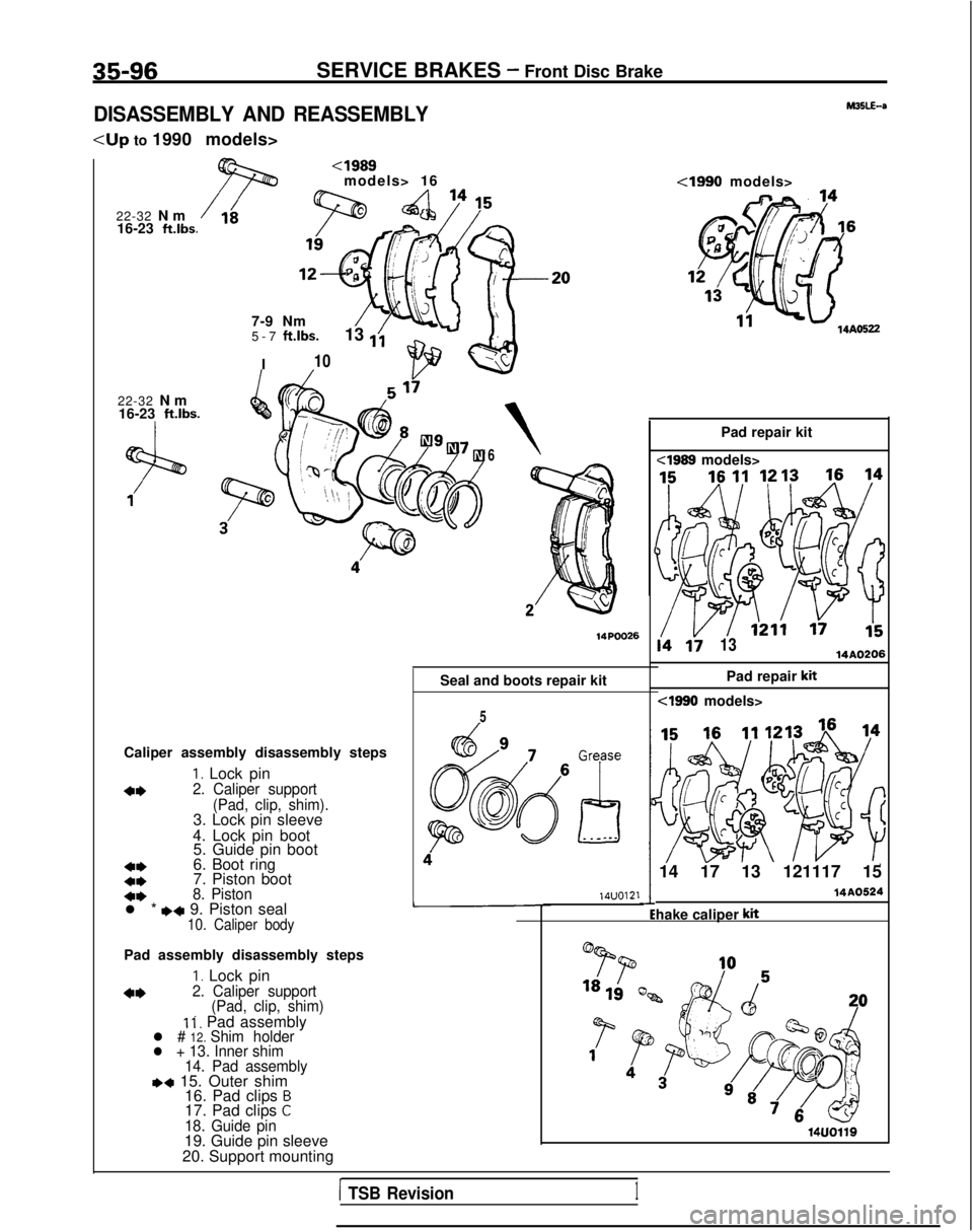
DISASSEMBLY AND REASSEMBLY
22-32 N
m
16-23
ft.lbs.
22-32 N
m
16-23
ft.lbs.
7-9 Nm
5-7
ft.lbs.
I 13
1;
10
6
Seal and boots repair kit
Caliper assembly disassembly steps
I. Lock pin
4*2. Caliper support (Pad, clip, shim).
3. Lock pin sleeve
4. Lock pin boot 5. Guide pin boot
4,6. Boot ring
c*7. Piston boot
+*8. Pistonl * I)* 9. Piston seal10. Caliper body
Pad assembly disassembly steps
I. Lock pin
4*2. Caliper support
(Pad, clip, shim) I
i, Pad assemblyl # 12. Shim holderl + 13. Inner shim
14. Pad assembly
,+ 15. Outer shim 16. Pad clips B17. Pad clips C18. Guide pin19. Guide pin sleeve
20. Support mounting L
5 14UO121
14AO522
Pad repair kit
i4 li1314A0206
Pad repair kit
cl990 models>
14 17 13 121117 15
hake caliper
kit
14A0524
1 TSB Revision1
Page 1218 of 1273
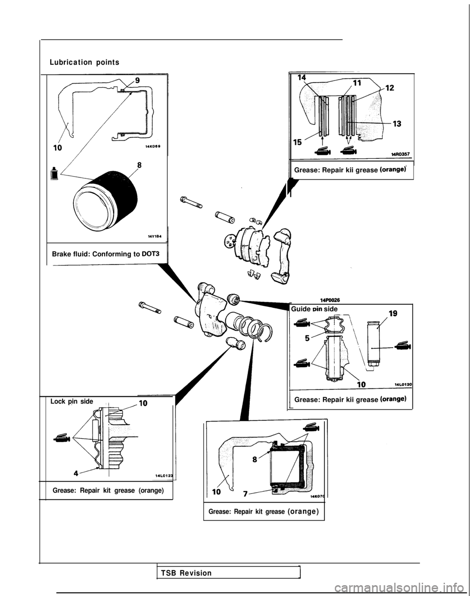
Lubrication points
I
8
Brake fluid: Conforming to DOT3
ND
Q?c/
Lock pin side,
Grease: Repair kii grease (orange)
7
Grease: Repair kit grease (orange)
14POO26
Guide Din side
Grease: Repair kii grease
(Orange)
Grease: Repair kit grease (orange)
TSB Revision
Page 1219 of 1273
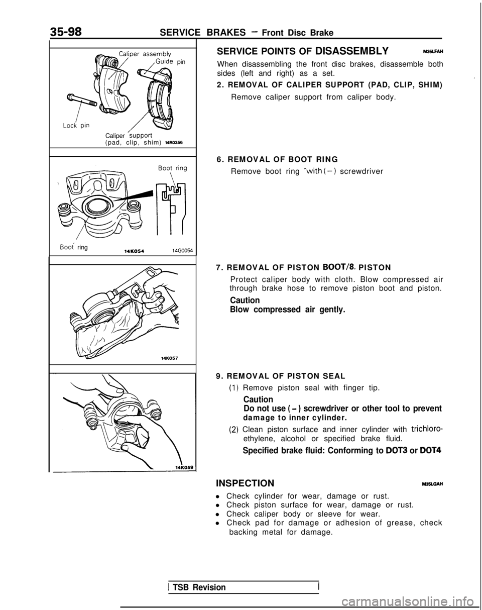
35-98SERVICE BRAKES - Front Disc Brake
pin
Caliper
/support(pad, clip, shim) 1410356
Boot ring14KO5414G0054 14KO57SERVICE POINTS OF DISASSEMBLY M35LFAH
When disassembling the front disc brakes, disassemble both
sides (left and right) as a set.
2. REMOVAL OF CALIPER SUPPORT (PAD, CLIP, SHIM)
Remove caliper support from caliper body.
6. REMOVAL OF BOOT RING Remove boot ring
*with (-) screwdriver
7. REMOVAL OF PISTON
BOOT/8. PISTON
Protect caliper body with cloth. Blow compressed air
through brake hose to remove piston boot and piston.
Caution
Blow compressed air gently.
9. REMOVAL OF PISTON SEAL
(1
(2
) Remove piston seal with finger tip.
Caution Do not use
( - ) screwdriver or other tool to prevent
damage to inner cylinder.
I) Clean piston surface and inner cylinder with trichloro-
ethylene, alcohol or specified brake fluid.
Specified brake fluid: Conforming to DOT3 or DOT4
INSPECTIONM35LGAH
l Check cylinder for wear, damage or rust.
l Check piston surface for wear, damage or rust.
l Check caliper body or sleeve for wear.
l Check pad for damage or adhesion of grease, check
backing metal for damage.
1 TSB Revision
Page 1220 of 1273
SERVICE BRAKES - Front Disc Brake35-99
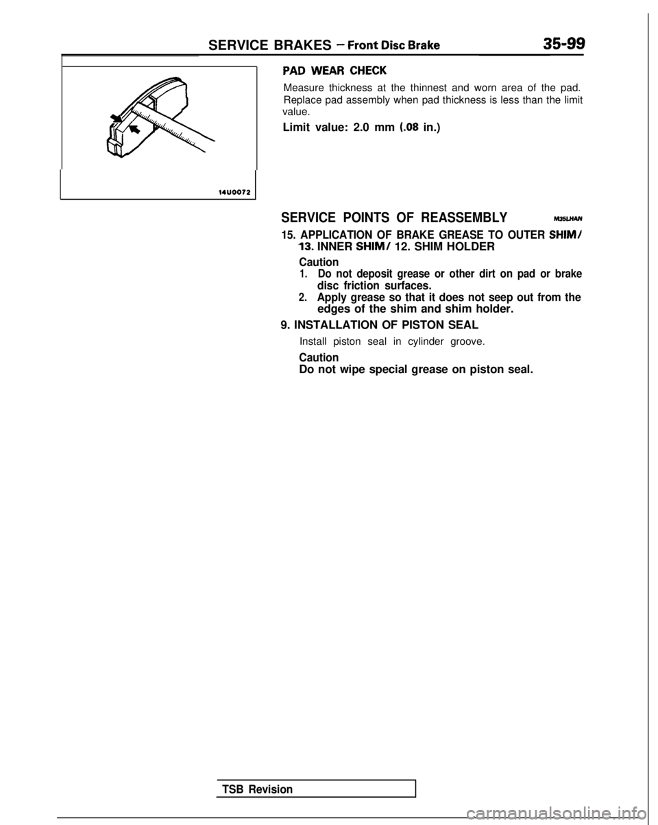
PAD WEAR CHECK
Measure thickness at the thinnest and worn area of the pad.
Replace pad assembly when pad thickness is less than the limit
value.
Limit value: 2.0 mm
(.08 in.)
14UOO72
SERVICE POINTS OF REASSEMBLYM35LHAN
15. APPLICATION OF BRAKE GREASE TO OUTER SHIM/
,13. INNER SHIM/ 12. SHIM HOLDER
Caution
1.Do not deposit grease or other dirt on pad or brake
disc friction surfaces.
2.Apply grease so that it does not seep out from the
edges of the shim and shim holder.
9. INSTALLATION OF PISTON SEAL Install piston seal in cylinder groove.
Caution
Do not wipe special grease on piston seal.
TSB Revision