MITSUBISHI GALANT 1989 Service Repair Manual
GALANT 1989
MITSUBISHI
MITSUBISHI
https://www.carmanualsonline.info/img/19/57312/w960_57312-0.png
MITSUBISHI GALANT 1989 Service Repair Manual
Trending: parking sensors, transmission oil, turn signal, remote control, change time, jump start, checking oil
Page 611 of 1273
INTAKE AND EXHAUST - Turbocharger15-25
35-50 Nm
25-3\6 fubs*
28-34 Nm
920-25 ftlbs.
3133
26H,a
/IW32Rk .p&
/25
55-65
40-47
25-36 ftlbs.
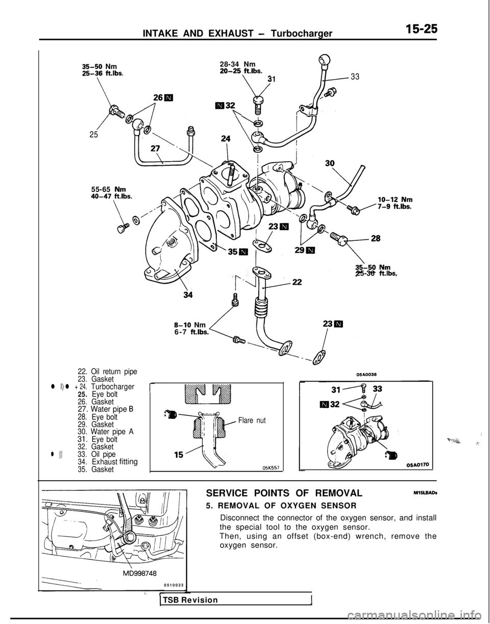
22. Oil return pipe23.Gasketl I) l + 24.Turbocharger
25. Eye bolt
26.Gasket27. Water pipe B28.Eye bolt29.Gasket
30. Water pipe A
31.Eye bolt32.Gasketl 433.Oil pipe34.Exhaustfitting35.Gasket
r
8-10 Nm
6-7 ft.lbs.
Flare nut OJK557
SERVICE POINTS OF REMOVAL
M15lBAoa
5. REMOVAL OF OXYGEN SENSOR Disconnect the connector of the oxygen sensor, and install
the special tool to the oxygen sensor.
Then, using an offset (box-end) wrench, remove the oxygen sensor.
0510023
I‘“*“n,&.”
1 TSB Revision
Page 612 of 1273
15-26INTAKE AND EXHAUST - Turbocharger
24. REMOVAL OF TURBOCHARGER ASSEMBLY Remove the turbocharger assembly with the exhaust fitting,
water pipe A, water pipe
B and the oil pipe attached to it.
33. REMOVAL OF OIL PIPE
Caution
After disconnecting the oil pipe, take care that foreign material does not enter the oil passage hole of the
turbocharger assembly.
INSPECTIONMlSLCAC
TURBOCHARGER ASSEMBLY CHECK
l Visually check the turbine wheel and the compressor wheel for cracking or other damage.
lCheck whether the turbine wheel and the compressor wheel
can be easily turned by hand.
l Check for oil leakage from the turbocharger assembly. 0
Check whether or not the turbocharger waste gate valve
remains open. If any problem is found, replace the part
after disassembly.
OIL PIPE AND OIL-RETURN PIPE CHECK
Check the oil pipe and oil-return pipe for clogging, bending, or
other damage. If there is clogging, clean it.
SERVICE POINTS OF INSTALLATION M15lDADa
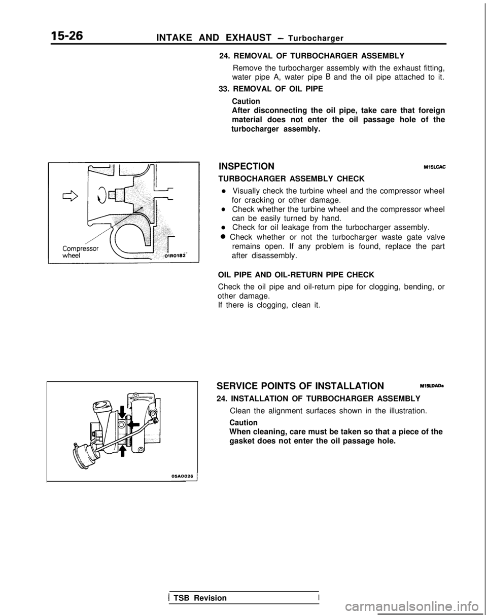
24. INSTALLATION OF TURBOCHARGER ASSEMBLY Clean the alignment surfaces shown in the illustration.
Caution
When cleaning, care must be taken so that a piece of thegasket does not enter the oil passage hole.
1 TSB RevisionI
Page 613 of 1273
INTAKE AND EXHAUST -Exhaust Manifold (SOHC-8 VALVE>15-27
EXHAUST MANIFOLD
models>
IEMOVAL AND INSTALLATIONYSNA-A
15-20
Nm
9-11 ftlbs.
40-50 Nm
Removal steps29 - 36 ft.lbs.
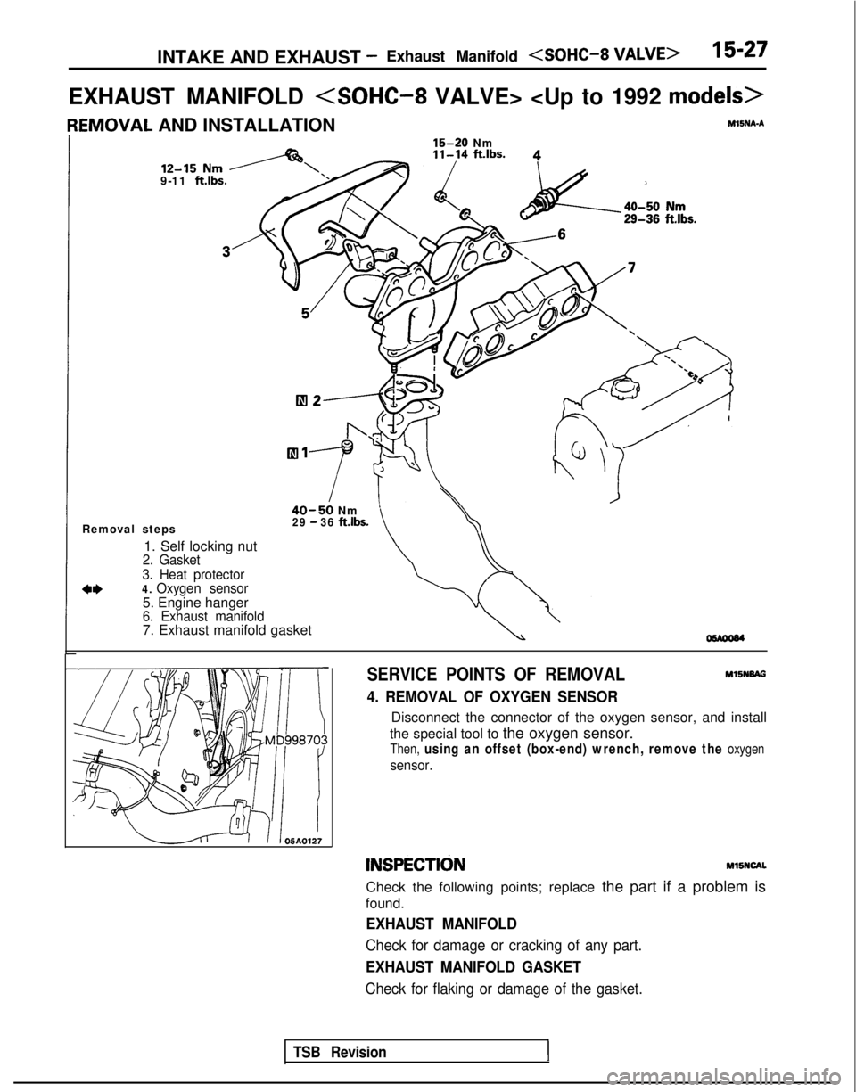
1. Self locking nut2. Gasket
3. Heat protector
a*4. Oxygen sensor
5. Engine hanger6. Exhaust manifold7. Exhaust manifold gasket
SERVICE POINTS OF REMOVAL MlSNBAG
4. REMOVAL OF OXYGEN SENSOR
Disconnect the connector of the oxygen sensor, and install
the special tool to the oxygen sensor.
Then, using an offset (box-end) wrench, remove the oxygen
sensor.
INSPECTldNMllNCAL
Check the following points; replace the part if a problem is
found.
EXHAUST MANIFOLD
Check for damage or cracking of any part.
EXHAUST MANIFOLD GASKET
Check for flaking or damage of the gasket.
TSB Revision1
Page 614 of 1273
15-28INTAKE AND EXHAUST - Exhaust Manifold
EXHAUST MANIFOLD
PEMOVAL AND INSTALLATION MlSNA-B
.15 Nm
1 ft.lbs.
7-l
40-50Nm ----‘--A
40-50 Nm /-29-36 ft.lbs.
30-40Nmj’22-29 ft.lbs.
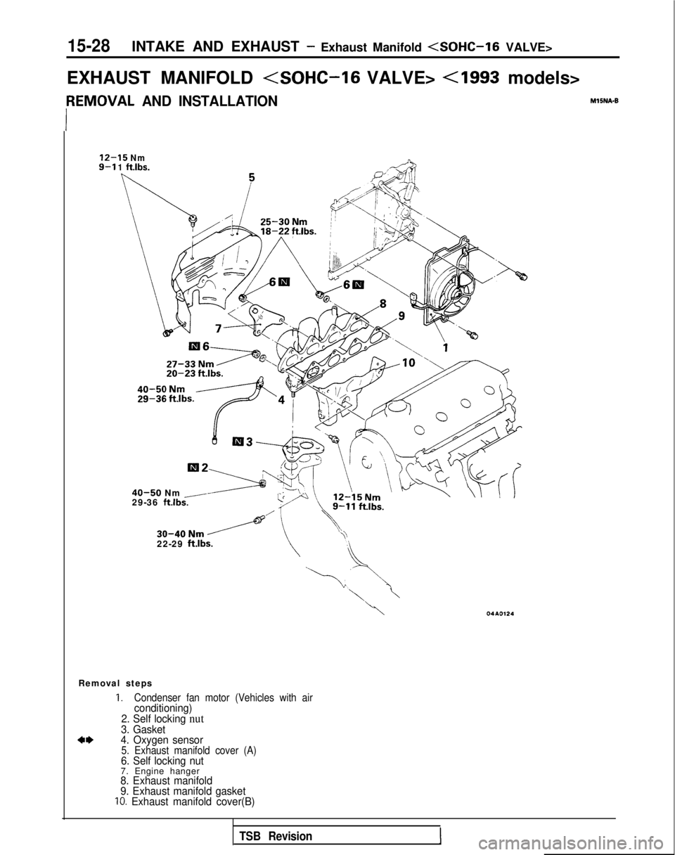
Removal steps
1.Condenser fan motor (Vehicles with airconditioning)
2. Self locking nut
3. Gasket
4*4. Oxygen sensor5. Exhaust manifold cover (A)6. Self locking nut7. Engine hanger8. Exhaust manifold
9. Exhaust manifold gasket
IO. Exhaust manifold cover(B)
TSB Revision1
Page 615 of 1273
INTAKE AND EXHAUST - Exhaust Manifold 15-29
SERVICE POINTS OF REMOVAL
MlBNBAFl
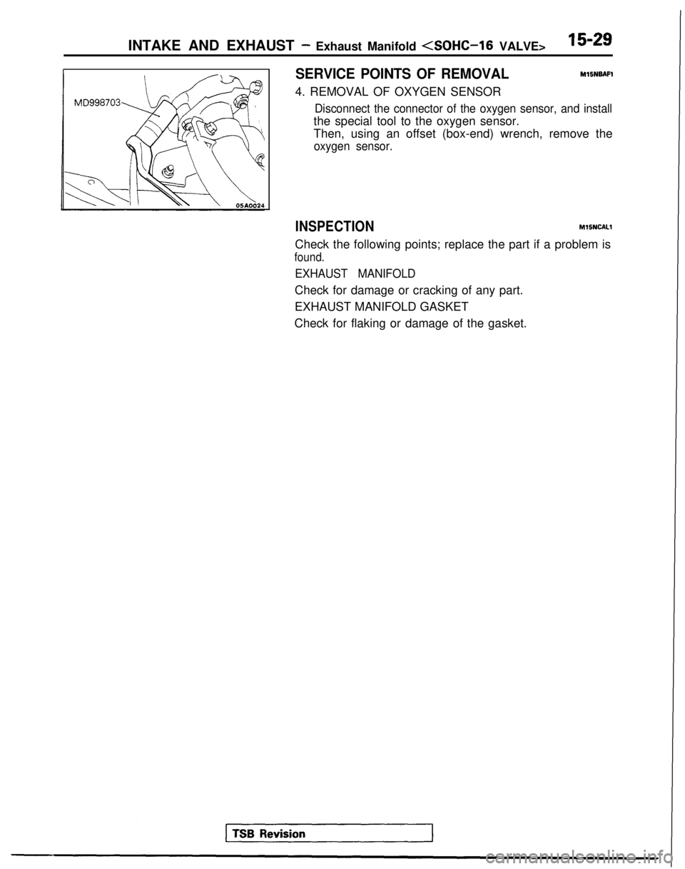
4. REMOVAL OF OXYGEN SENSOR
Disconnect the connector of the oxygen sensor, and install
the special tool to the oxygen sensor.
Then, using an offset (box-end) wrench, remove the
oxygen sensor.
INSPECTION MlSNCALl
Check the following points; replace the part if a problem is
found.
EXHAUST MANIFOLD
Check for damage or cracking of any part.
EXHAUST MANIFOLD GASKET
Check for flaking or damage of the gasket.
Page 616 of 1273
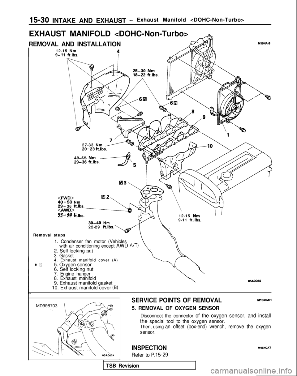
15-30 INTAKE AND EXHAUST -Exhaust Manifold
EXHAUST MANIFOLD
REMOVAL AND INSTALLATION
I12-15 Nm9- 11ft.lbs.
27-33 Nm20-23 fklbs.
40 50 Nm29136 ft.lbs.yAS
40-50Nm29- 36ft.lbs.30-40Nm22- 29ft.lbs.12-15 1
30-40Nm9-11 ft.
\
UrnIbs.
MlINA-B
22-29 ft.lbs
Removal steps*b’.
1. Condenser fan motor (Vehicles with air conditioning except AWD A/T)
2. Self locking nut3. Gasket4. Exhaust manifold cover (A)
l *5. Oxygen sensor
6. Self locking nut
7. Engine hanger
8. Exhaust manifold
9. Exhaust manifold gasket
10. Exhaust manifold cover (B)
SERVICE POINTS OF REMOVALMl5NNAH
5. REMOVAL OF OXYGEN SENSOR
Disconnect the connector of the oxygen sensor, and install
the special tool to the oxygen sensor.
Then, using an offset (box-end) wrench, remove the oxygen
sensor.
INSPECTION
Refer to P.15-29i
TSB Revision M15NCA-l
Page 617 of 1273
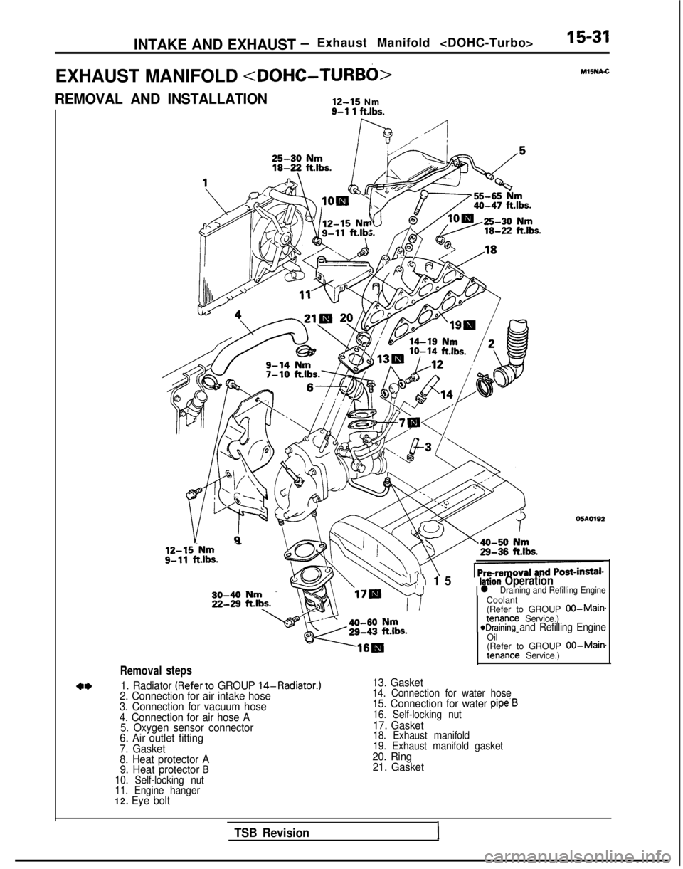
INTAKE AND EXHAUST -Exhaust Manifold 15-31
EXHAUST MANIFOLD
REMOVAL AND INSTALLATION
12-15
Nm
Removal
12-15.Nm - g-11
ft.lbs.
steps
9-l 1 ftlbs.
lh ./-I
‘Uc Ml5NA.C
05AO192
Coolant
(Refer to GROUP
00-Maimtenance Service.)eDraining and Refilling Engine
1. Radiator (Referto GROUP 14-Radiator.)
2. Connection for air intake hose
3. Connection for vacuum hose
4. Connection for air hose A 5. Oxygen sensor connector
6. Air outlet fitting
7. Gasket
8. Heat protector A 9. Heat protector
B10. Self-locking nut
11. Engine hanger
12. Eye bolt
‘\!I 1
5
Ilation Operationl Draining and Refilling Engine
Oil
-
(Refer to GROUP 00-Main.tenance Service.)
13. Gasket14. Connection for water hose15. Connection for water pipe.B16. Self-locking nut17. Gasket18. Exhaust manifold
19. Exhaust manifold gasket
20. Ring
21. Gasket
TSB Revision1
Page 618 of 1273
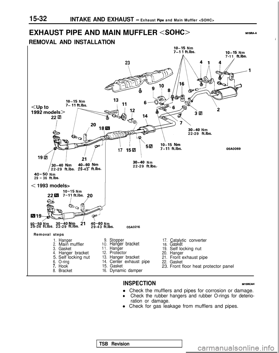
15-32INTAKE AND EXHAUST - Exhaust Pipe and Main Muffler
EXHAUST PIPE AND MAIN MUFFLER M15RA.A
iREMOVAL AND INSTALLATION
IO-15 Nm7-l 1 ft.lbs.
h
lo-15 Nm
7-11 ft.lbs.
IO-15 Nm7- 11 ft.lbs.
23 30-40
Nm
22-29
ft.lbs.
’1715lIl 30-40
Nm
22-29ftlbs.29-43ft.lbs.22-29ft.lbs.
40-50Nm29 - 36ftlbs.
05A0069
< 1993 models>
IO-15 Nm22.1
7-11
ftlbs.20
40-50
Nm30-40Nm2140-60Nm29-36ft.lbs.22-29 ft.lbs.29-43
ftlbs.05A0216
Removal steps
1.Hanger2.Main muffler3.Gasket4.Hanger bracket5. Self locking nut6.O-ring7.Hook8.Bracket
9.Stopper
10.Hanger bracket11.Hanger12.Protector13.Hanger bracket14.Center exhaust pipe15. Gasket16.Dynamic damper
17.Catalytic converter18.Gasket19.Self locking nut20.Hanger21.Front exhaust pipe22.Gasket23. Front floor heat protector panel
INSPECTION
MlSRCAH
l Check the mufflers and pipes for corrosion or damage.
lCheck the rubber hangers and rubber O-rings for deterio- ration or damage.
l Check for gas leakage from mufflers and pipes.
TSB Revision
Page 619 of 1273
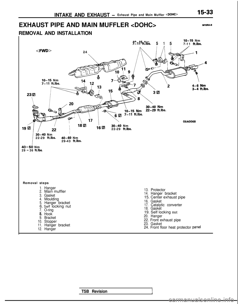
INTAKE AND EXHAUST -Exhaust Pipe and Main Muffler
EXHAUST PIPE AND MAIN MUFFLER
15-33M15R4-8
REMOVAL AND INSTALLATION
24
IO-15 Nmlo-15 Nm
7-11ft.lbs.5157-11ft.lbs.,
,IO-15
Nm 7-11
ft.lbs.
30-40 Nm
22-29 ft.lbs.
30-40 NmI
22-29 ft.lbs. 40-60
Nm
29-43 ftlbs.
40-50 Nm29 - 36 ft.lbs.
Removal steps
1.Hanger2.Main muffler
3.Gasket4.Moulding5.Hanger bracket6. Self locking nut7.O-ring
8.Hook9.Bracket10.Stopper11.Hanger bracket12.Hanger
13.Protector14.Hanger bracket15. Center exhaust pipe
16.Gasket17.Catalytic converter18.Gasket19. Self locking nut20.Hanger
22. Front exhaust pipe23. Gasket24. Front floor heat protector panel
TSB RevisionI
Page 620 of 1273
15-34INTAKE AND EXHAUST -Exhaust Pipe and Main Muffler
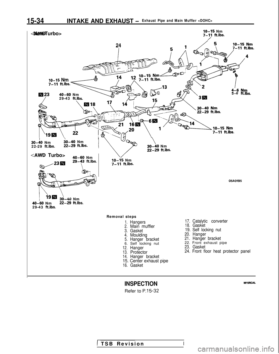
lo-15 Nm
7-Y ft*lbs.
10-15 Nm
7-11
ft.lbs
24
lN2340-60 Nm
/29-43 ft.lb
3-4 ft.lbs. 30-10
Nm
$0-40 Nm
22-29
ft.lbs. 22-29
ft.lbs.I
Turbo>
40-60 Nm29-y ft.lbs.
/\Ignr ?,40 Nm 40-60
Nm 22-29
ft.lbs.29-43 ft.lbs.
\30-40 NmZ-29 ft.lbs.
IO-15 Nm7-11 ft.lbs.
05A0195
Removal steps
1.Hangers2.Main muffler3.Gasket4.Moulding5.Hanger bracket6. Self locking nut12.Hanger13.Protector14.Hanger bracket15. Center exhaust pipe16.Gasket
17.Catalytic converter18.Gasket
19. Self locking nut
20.Hanger21.Hanger bracket22. Front exhaust pipe23.Gasket
24. Front floor heat protector panel
INSPECTION
Refer to P.15-32 MllRCAL
1 TSB Revisio
n
I
Trending: 4WD, charging, tire size, oil change, fuel filter, steering, coolant reservoir
