MITSUBISHI GALANT 1989 Service Repair Manual
Manufacturer: MITSUBISHI, Model Year: 1989, Model line: GALANT, Model: MITSUBISHI GALANT 1989Pages: 1273, PDF Size: 37.62 MB
Page 601 of 1273
INTAKE AND EXHAUST -Intake Manifold
lo-13 Nm
r
7-9 ftlbs.IO-13 Nm7-9 ftlbs.
IS-20 Nm
11-14 ft Ibs-- -- --I-
7-11 ft.lbs
‘S-20 Nm11-14 ftlbs.
9- 11
ftlbs.lo-13 Nm7-9
ftlbs.
20-40 Nm,14-28 ft.lbs.
osAooss
--l8
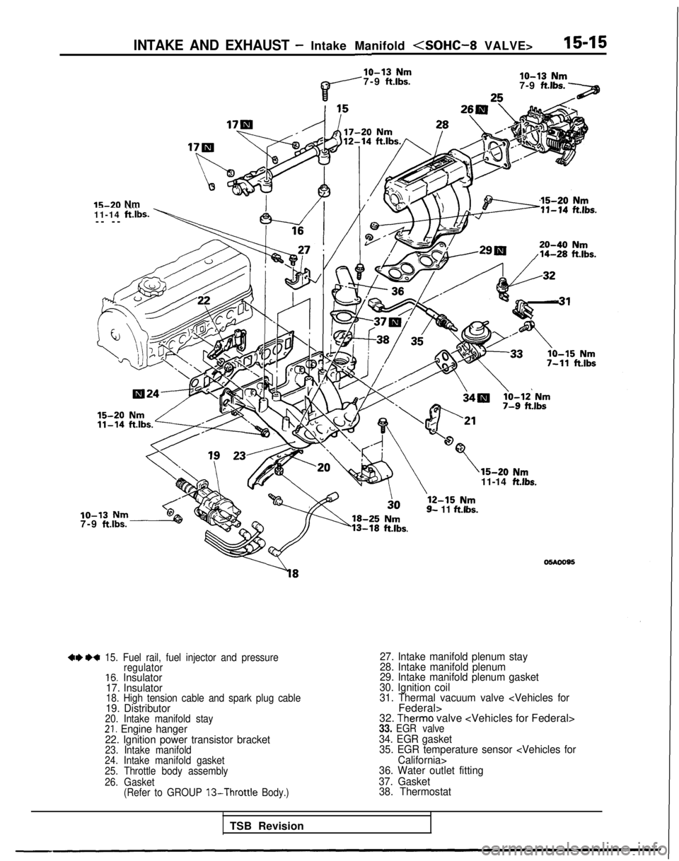
++ ** 15. Fuel rail, fuel injector and pressure
regulator
16. Insulator
17. Insulator
18. High tension cable and spark plug cable19. Distributor20. Intake manifold stay21. Engine hanger
22. Ignition power transistor bracket
23. Intake manifold
24. Intake manifold gasket
25. Throttle body assembly
26. Gasket (Refer to GROUP
13-Throttle Body.)
27. Intake manifold plenum stay
28. Intake manifold plenum
29. Intake manifold plenum gasket
30. Ignition coil
31. Thermal vacuum valve
32. Therm0 valve
35. EGR temperature sensor
36. Water outlet fitting
37. Gasket 38. Thermostat
TSB Revision
Page 602 of 1273
15-16INTAKE AND EXHAUST- Intake Manifold
05AOO89
I05A0081
(
SERVICE POINTS OF REMOVALM15M9Ah
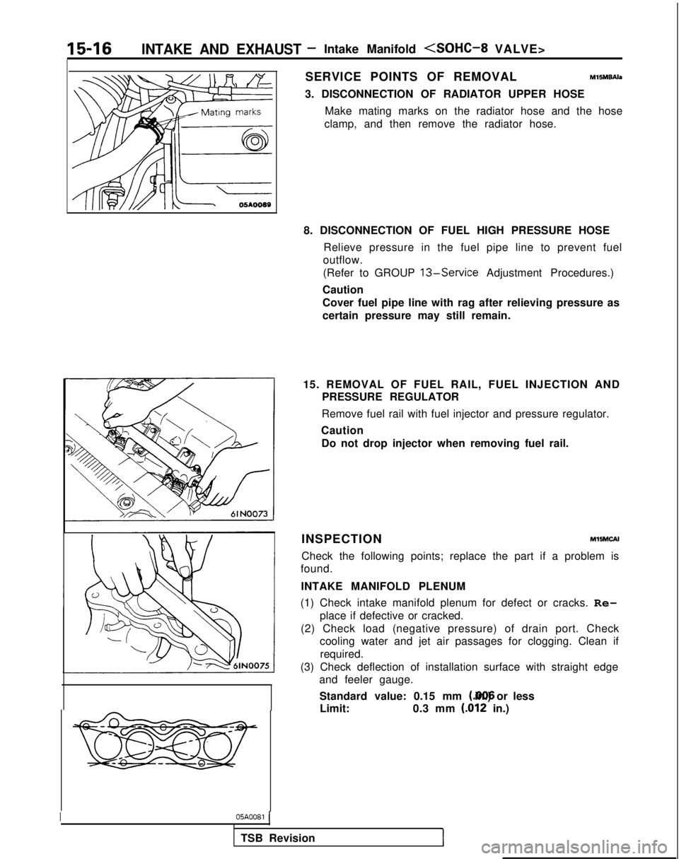
3. DISCONNECTION OF RADIATOR UPPER HOSE
Make mating marks on the radiator hose and the hose
clamp, and then remove the radiator hose.
8. DISCONNECTION OF FUEL HIGH PRESSURE HOSE Relieve pressure in the fuel pipe line to prevent fuel
outflow.
(Refer to GROUP
13-Service Adjustment Procedures.)
Caution
Cover fuel pipe line with rag after relieving pressure as
certain pressure may still remain.
15. REMOVAL OF FUEL RAIL, FUEL INJECTION AND PRESSURE REGULATOR
Remove fuel rail with fuel injector and pressure regulator.
Caution Do not drop injector when removing fuel rail.
INSPECTION
MlSMCAI
Check the following points; replace the part if a problem is
found.
INTAKE MANIFOLD PLENUM
(1) Check intake manifold plenum for defect or cracks. Re- place if defective or cracked.
(2) Check load (negative pressure) of drain port. Check cooling water and jet air passages for clogging. Clean if
required.
(3) Check deflection of installation surface with straight edge and feeler gauge.
Standard value: 0.15 mm (.006 in.) or less
Limit: 0.3 mm
(.012 in.)
1
TSB Revision
Page 603 of 1273
INTAKE AND EXHAUST -Intake Manifold
15-17
\
05A0074
TSB Revision
I
INTAKE MANIFOLD
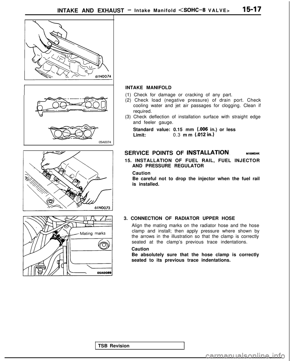
(1) Check for damage or cracking of any part.
(2) Check load (negative pressure) of drain port. Check cooling water and jet air passages for clogging. Clean if
required.
(3) Check deflection of installation surface with straight edge
and feeler gauge.
Standard value: 0.15 mm I.006
in.) or less
Limit: 0.3
mm
(.012 in.1
SERVICE POINTS OF INSTALLATION,MlSMDAK
15. INSTALLATION OF FUEL RAIL, FUEL INJECTOR
AND PRESSURE REGULATOR
Caution
Be careful not to drop the injector when the fuel rail
is installed.
3. CONNECTION OF RADIATOR UPPER HOSE Align the mating marks on the radiator hose and the hoseclamp and install; then apply pressure where shown by
the arrows in the illustration so that the clamp is correctly
seated at the clamp’s previous trace indentations.
Caution Be absolutely sure that the hose clamp is correctly
seated to its previous trace indentations.
Page 604 of 1273
15-18INTAKE AND EXHAUST - Intake Manifold (SOHC-16 VALVE>
INTAKE MANIFOLD
REMOVAL AND INSTALLATION< 1993 models>
?.llSt.lA-A
4-6 N
m
3-4
ft.lbs.
7#jfi6
/ '
6-8 ft.lbs.
2
10OSAO215
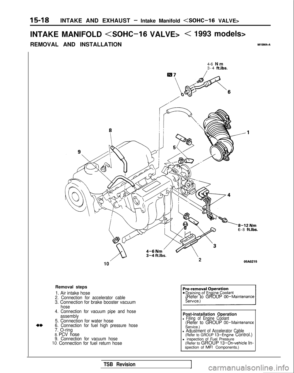
Removal steps
1. Air intake hose2. Connection for accelerator cable3. Connection for brake booster vacuumhose
4. Connection for vacuum pipe and hose
assembly
5. Connection for water hose6. Connection for fuel high pressure hose7. O-ring8. PCV hose9. Connection for vacuum hoseIO. Connection for fuel return hose (Refer to GROUP
OO-Maintenance
Post-installation Operationl
Filling of Engine Coolant(Refer to GROUP 00-MaintenanceService.)l Adjustment of Accelerator Cable(Refer to GROUP 13-Engine Control.)l inspection of Fuel Pressure
(Refer to GROUP 13-On-vehicle In-
spection of MFI
Components.)
TSB Revision
Page 605 of 1273
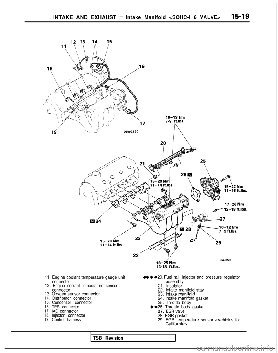
INTAKE AND EXHAUST -Intake Manifold
16
\305A0220
lo-13 Nm7-9 ft.lbs.
/R24
,,/13-18 ft.lbs.
’15-20 Nm11-14ft.lbs.
11. Engine coolant temperature gauge unitconnector
12. Engine coolant temperature sensor
connector
13. Oxygen sensor connector
14.Distributor connector15.Condenser connector16.TPS connector17.IAC connector18.injector connector19.Control harness
18-2iNm13-18 ft.lbs.
05AO222
4I) 1)+20. Fuel rail, injector and pressure regulator
assembly
21. Insulator
22. Intake manifold stay
23. Intake
manifold24. Intake manifoii gasket
25. Throttle body
1)+26. Throttle body gasket27. EGR valve28. EGR gasket
29. EGR temperature sensor
TSB RevisionI
Page 606 of 1273
15-20INTAKE AND EXHAUST - Intake Manifold (SOHC-16 VALVE>
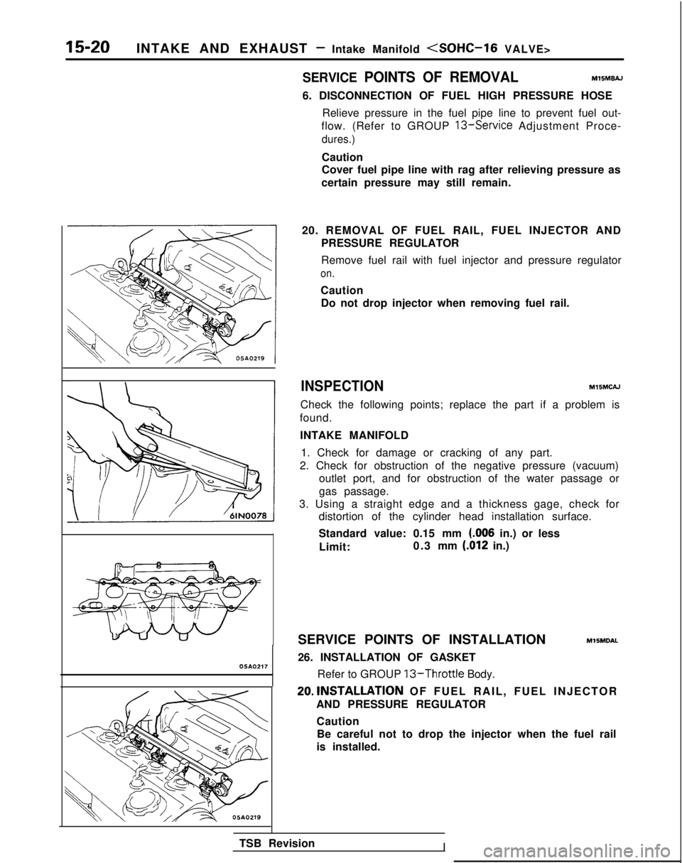
05AO217
SERVICE POINTS OF REMOVALMlSMBAJ
6. DISCONNECTION OF FUEL HIGH PRESSURE HOSERelieve pressure in the fuel pipe line to prevent fuel out-
flow. (Refer to GROUP
13-Service Adjustment Proce-
dures.)
Caution
Cover fuel pipe line with rag after relieving pressure as
certain pressure may still remain.
20. REMOVAL OF FUEL RAIL, FUEL INJECTOR AND PRESSURE REGULATOR
Remove fuel rail with fuel injector and pressure regulator
on.
CautionDo not drop injector when removing fuel rail.
INSPECTIONMlSMCAJ
Check the following points; replace the part if a problem is
found.
INTAKE MANIFOLD 1. Check for damage or cracking of any part.
2. Check for obstruction of the negative pressure (vacuum) outlet port, and for obstruction of the water passage or
gas passage.
3. Using a straight edge and a thickness gage, check for distortion of the cylinder head installation surface.
Standard value: 0.15 mm
(006 in.) or less
Limit: 0.3 mm
(.012 in.)
SERVICE POINTS OF INSTALLATION
MllMDAL
26. INSTALLATION OF GASKET Refer to GROUP
13-Throttle Body.
20.lNSTALLATlON OF FUEL RAIL, FUEL INJECTOR
AND PRESSURE REGULATOR
CautionBe careful not to drop the injector when the fuel rail
is installed.
TSB Revision
I
Page 607 of 1273
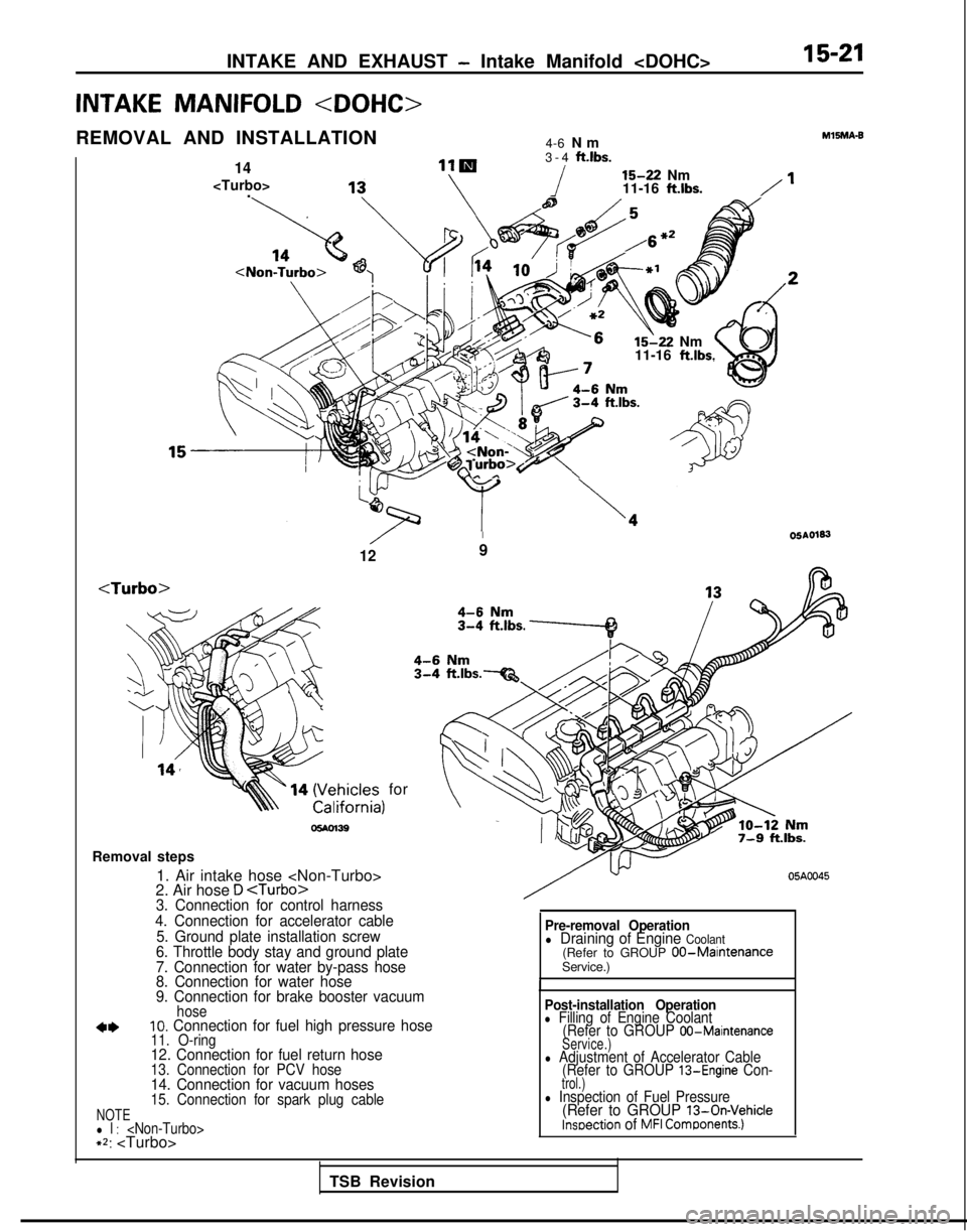
INTAKE AND EXHAUST - Intake Manifold
INTAKE MANIFOLD
REMOVAL AND INSTALLATION 4-6 Nm
14
. 3-4
ft.lbs.
i 15-22
Nm
11-16 ft.lbs./’
/6 *= 15-22
Nm
11-16
ft.lbs.
‘urbo>fl\sT
M15MA-9
/I05AO183
129
for
o!wn39
Removal steps 1. Air intake hose
2. Air hose
D
4. Connection for accelerator cable 5. Ground plate installation screw
6. Throttle body stay and ground plate
7. Connection for water by-pass hose
8. Connection for water hose
9. Connection for brake booster vacuum
hose10. Connection for fuel high pressure hose11. O-ring12. Connection for fuel return hose13. Connection for PCV hose14. Connection for vacuum hoses15. Connection for spark plug cableNOTEl l :
05A0045
Pre-removal Operationl Draining of Engine Coolant(Refer to GROUP 00-MaintenanceService.)
Post-installation Operationl Filling of Engine Coolant (Refer to GROUP 00-Maintenance
Service.)
l Adjustment of Accelerator Cable (Refer to GROUP 13-Engine Con-trol.)l Inspection of Fuel Pressure(Refer to GROUP 13-On-Vehiclelnseection of MFI Comgonents.)
TSB Revision
Page 608 of 1273
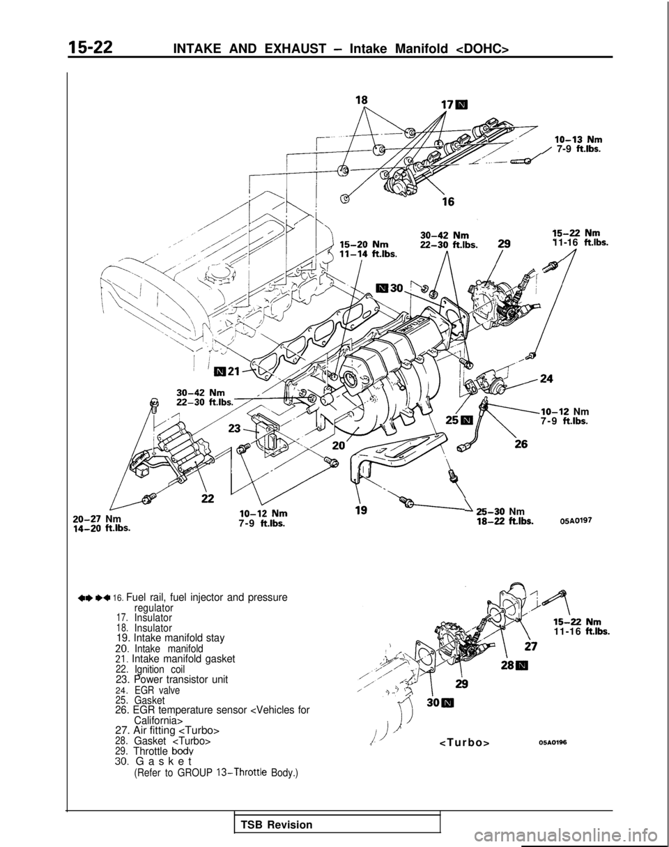
15-22INTAKE AND EXHAUST - Intake Manifold
lo-13 Nm/ 7-9 ftlbs.
15-22 Nm11-16
ftlbs.
n
20-27 Nm14-20 ft.lbs.7-9
ftlbs.
+e I)4 16. Fuel rail, fuel injector and pressureregulator17.Insulator18.Insulator19. Intake manifold stay20.Intake manifold21. Intake manifold gasket22.Ignition coil23. Power transistor unit24.EGR valve
25.Gasket26. EGR temperature sensor
27. Air fitting
t
(Refer to GROUP 13-Throttle
Body.)
lo-12 Nm
7-9 ft.lbs.
125-30 Nm18-22 ftlbs.05AQ197
15-2211-16
OSAO196
TSB Revision
Page 609 of 1273
INTAKE AND EXHAUST - Intake Manifold
SERVICE POINTS OF REMOVAL
M1SMEAJa
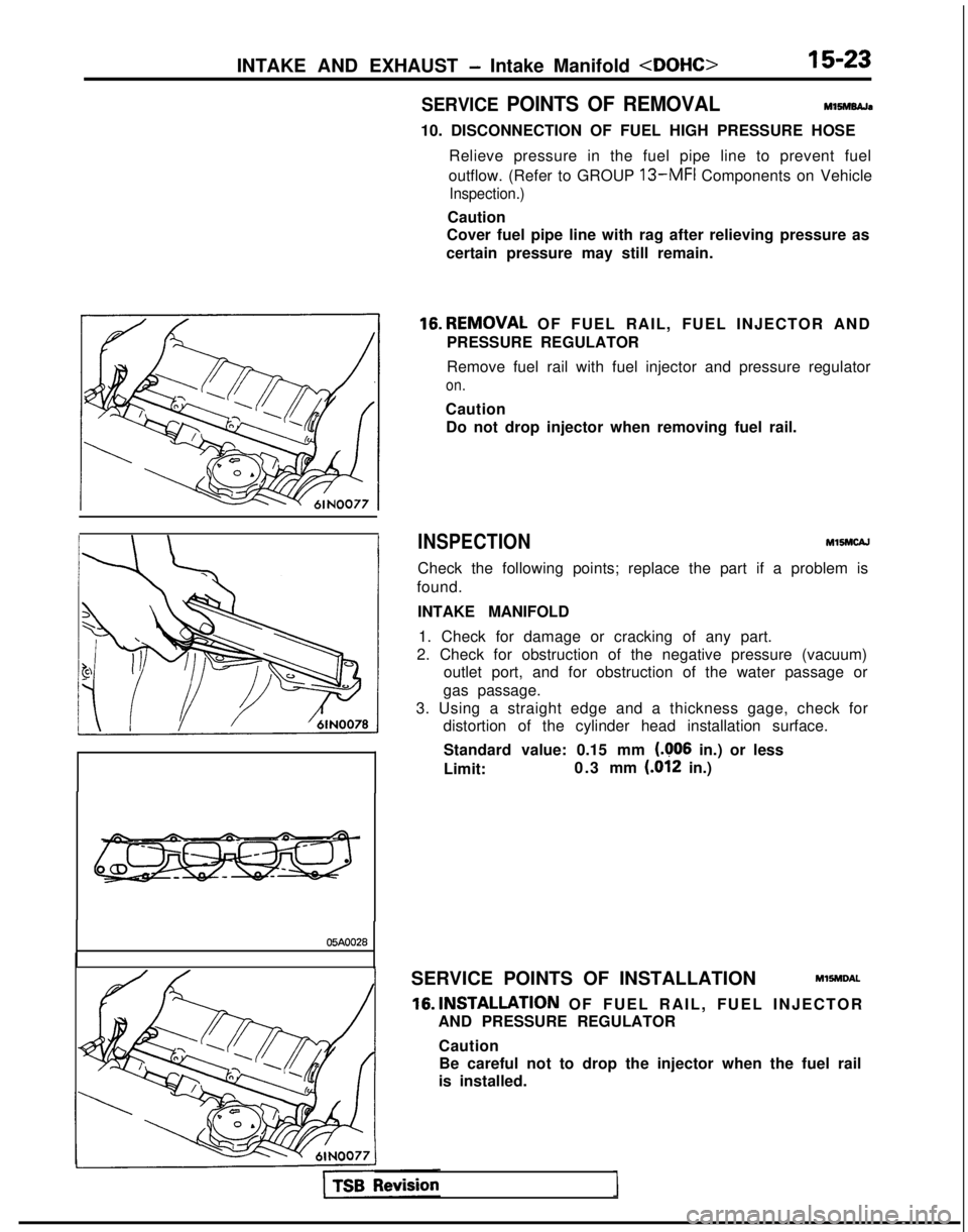
10. DISCONNECTION OF FUEL HIGH PRESSURE HOSE Relieve pressure in the fuel pipe line to prevent fuel
outflow. (Refer to GROUP
13-MFI Components on Vehicle
Inspection.)
Caution
Cover fuel pipe line with rag after relieving pressure as
certain pressure may still remain.
16.REMOVAL OF FUEL RAIL, FUEL INJECTOR AND
PRESSURE REGULATOR
Remove fuel rail with fuel injector and pressure regulator
on.
Caution Do not drop injector when removing fuel rail.
INSPECTION MlSMCAJ
Check the following points; replace the part if a problem is
found.
INTAKE MANIFOLD1. Check for damage or cracking of any part.
2. Check for obstruction of the negative pressure (vacuum) outlet port, and for obstruction of the water passage or
gas passage.
3. Using a straight edge and a thickness gage, check for distortion of the cylinder head installation surface.
Standard value: 0.15 mm
(406 in.) or less
Limit: 0.3 mm (.012
in.)
05AOO28
SERVICE POINTS OF INSTALLATIONMlSMDAL
16.lNSTALLATlON OF FUEL RAIL, FUEL INJECTOR
AND PRESSURE REGULATOR
CautionBe careful not to drop the injector when the fuel rail
is installed.
Page 610 of 1273
15-24INTAKE AND EXHAUST - Turbocharger
TURBOCHARGER
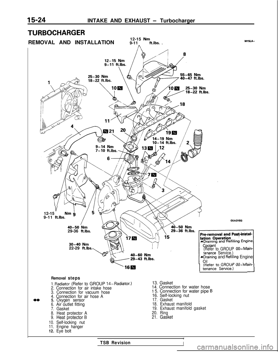
REMOVAL AND INSTALLATION12-15 Nm9-11 ft.lbs. )n
MlSLA-
40-47 ftlbs.
v I”12-15 Nm g
9-11 ftlbs.
i40-50 Nm29-36 ft.lbs.
05A0193
30-40 Nm22-29 ftlbs. *Draining
andRefilling Engine
(Refer to GROUPOO-Main-tenance Service.)aDraining and Refilling Engine
---. .- _^ . ._;_I(Refer to CiKUUi-’
UU-M~III-11
tenance Service.)-I
Removal steps
1.
Radiator (Refer to GROUP 14-Radiator.)
13. Gasket2. Connection for air intake hose14. Connection for water hose
3. Connection for vacuum hoseI 5. Connection for water pipe B
4. Connection for air hose A16. Self-locking nut
4*5.Oxygen sensor17.Gasket
6.Air outlet fitting18.Exhaust
manifold
7.Gasket19.Exhaustmanifold
gasket
8.Heat protector A 20.Ring
9.Heat protector B21.Gasket
10.Self-locking nut11.Engine hanger
12. Eye bolt
1‘
TSB RevisionI