MITSUBISHI GALANT 1989 Service Repair Manual
GALANT 1989
MITSUBISHI
MITSUBISHI
https://www.carmanualsonline.info/img/19/57312/w960_57312-0.png
MITSUBISHI GALANT 1989 Service Repair Manual
Trending: tire type, ground clearance, headlamp, differential, brake sensor, change wheel, open gas tank
Page 631 of 1273
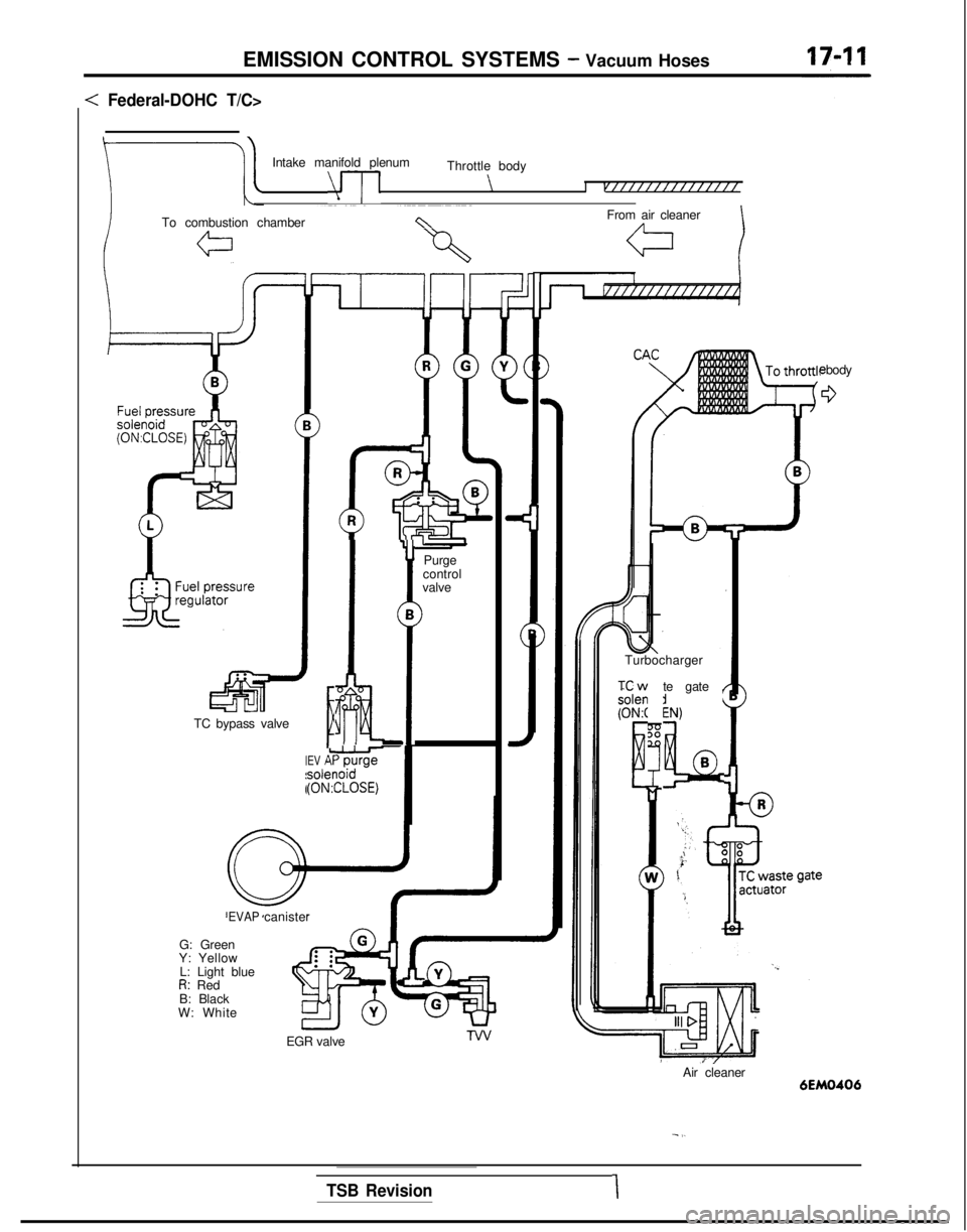
EMISSION CONTROL SYSTEMS - Vacuum Hoses
: Federal-DOHC T/C>
Intake manifold plenum
\--p
Throttle body
\I vff/ffffffffffff
ITo combustion chamberc\From air cleaner
a
e body
0
l5Bii-TC bypass valve
Y
Purge
control
valve B
>
1.fi. .
EV ALi1;o?psoler(ON3ZLOSEi)
EVAPcanister
Turbocharger
ixw solen
(ONA
E
te gate ,
:N,
!4Q
B
G: Green
Y: Yellow
L: Light blue
R: Red
B: Black
W: White
EGR valve
Air cleaner
6EM0406
- I.
TSB Revision1
Page 632 of 1273
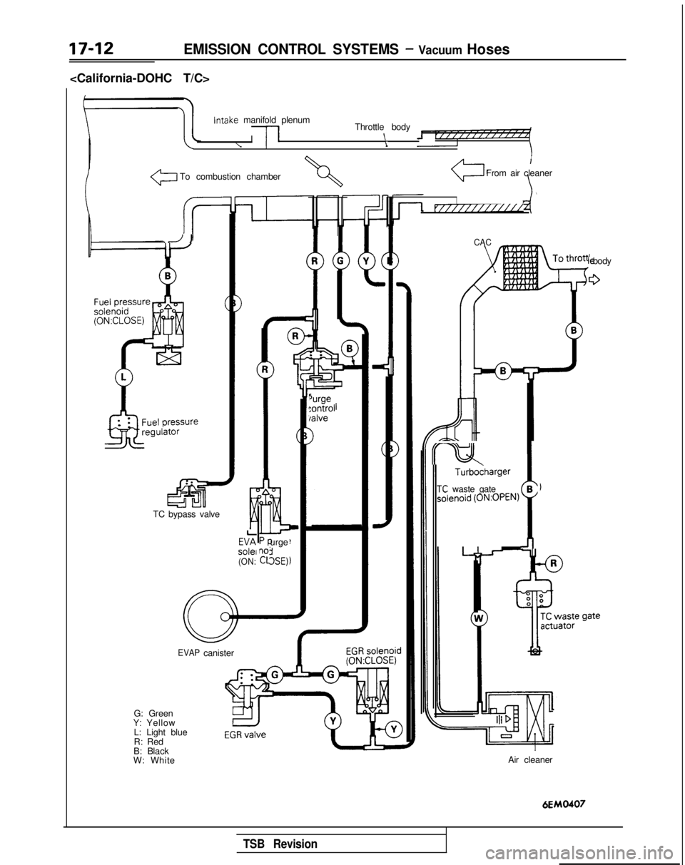
EMISSION CONTROL SYSTEMS - Vacuum Hoses
Intake
manifold plenum
I
/I
Throttle body \
\i
To combustion chamber
I
From air cleaner
IVI////////////
.J JCAC
le body
G
Turbodharger
TC waste gateB
- ;
Sl
slenoid
(0N:OPEN)
urge
:SE)
‘urge:ontrol /alve
TC bypass valve EV?
solei
(ON:
EVAP
canister
G: Green
Y: Yellow
L: Light blue
R: Red
B: Black
W: White Air cleaner
6EMO407
TSB Revision
Page 633 of 1273
EMISSION CONTROL SYSTEMS -Vacuum Hoses/Positive Crankcase Ventilation System17-13
INSPECTIONMl7JcAo
(1) Referring to the VACUUM HOSES ROUTING, confirm thatthe vacuum hoses are properly connected.
(2) Check the hoses for irregularities (disconnection, loose-ness, etc.) and confirm that there is no breakage or
damage.
INSTALLATION Ml7JDAD
(1) When connecting a hose, firmly press it onto the nipple.
(2) Referring to the VACUUM HOSES ROUTING, connect the hoses correctly.
POSITIVE CRANKCASE VENTILATION SYSTEMM171A-
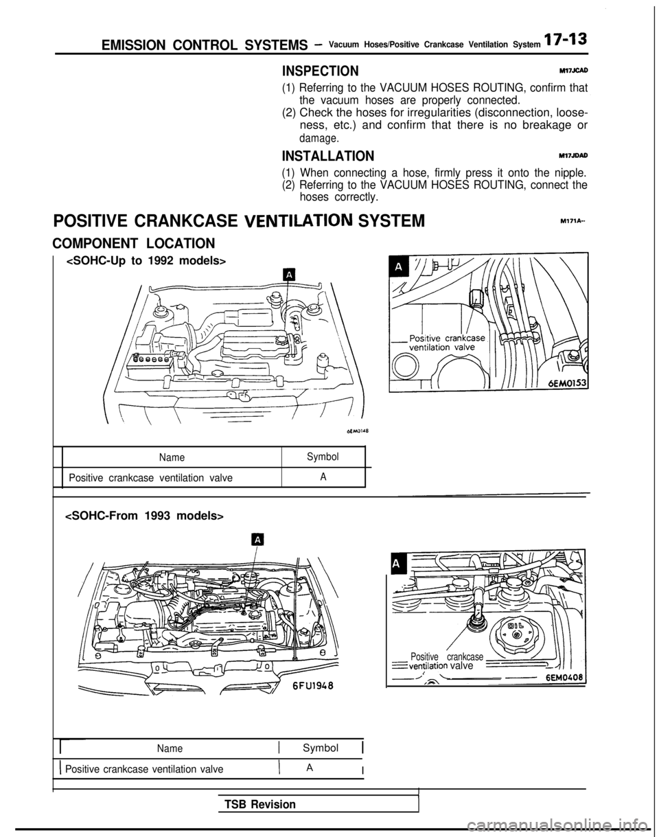
COMPONENT LOCATION
Name Symbol
Positive crankcase ventilation valveA
Name1 Symbol 1
1 Positive crankcase ventilation valveI A I
Positive crankcase---ventilation
valveI
ITSB Revision
Page 634 of 1273
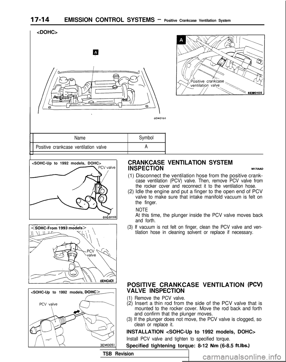
17-14EMISSION CONTROL SYSTEMS -Positive Crankcase Ventilation System
NameSymbol
Positive crankcase ventilation valve A
OlGOllO
CRANKCASE VENTILATION SYSTEM
INSPECTIONM17IAAO
(1) Disconnect the ventilation hose from the positive crank-
case ventilation (PCV) valve. Then, remove PCV valve from
the rocker cover and reconnect it to the ventilation hose.
(2) Idle the engine and put a finger to the open end of PCV
valve to make sure that intake manifold vacuum is felt on
the finger.
NOTE
At this time, the plunger inside the PCV valve moves back
and forth.
(3) If vacuum is not felt on finger, clean the PCV valve and ven- tilation hose in cleaning solvent or replace if necessary.
POSITIVE CRANKCASE VENTILATION (PCV)
VALVE INSPECTION
(1) Remove the PCV valve.
(2) Insert a thin rod from the side of the PCV valve that is
mounted to the rocker cover. Move the rod back and forth
and confirm that the plunger moves.
(3) If the plunger does not move, the PCV valve is clogged, so
clean or replace it.
INSTALLATION
Install PCV valve and tighten to specified torque.
Specified tightening torque: 8-12 Nm (6-8.5 ftlbs.)
TSB Revision
Page 635 of 1273
EMISSION CONTROL SYSTEMS -Positive Crankcase Ventilation System/
Evaporative emission Control System17-15
_
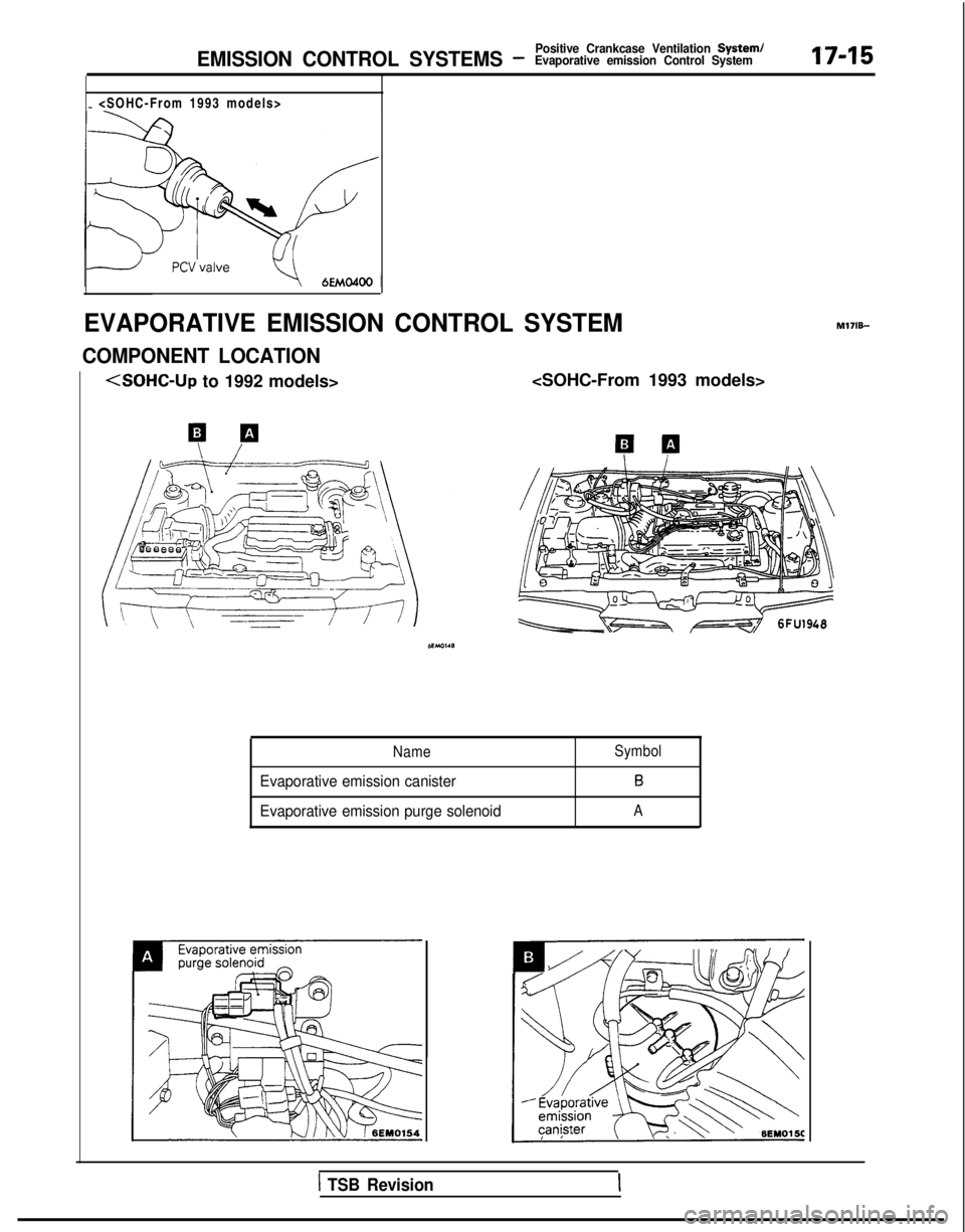
EVAPORATIVE EMISSION CONTROL SYSTEM
COMPONENT LOCATION M171B-
to 1992 models>
Name
Evaporative emission canister
Evaporative emission purge solenoid
Symbol
B
A
1 TSB Revision
Page 636 of 1273
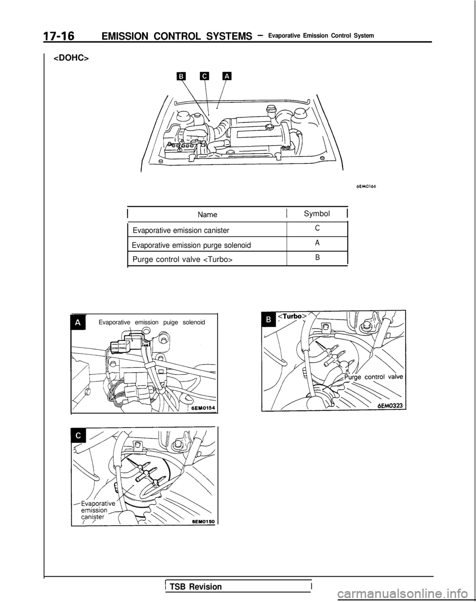
17-16EMISSION CONTROL SYSTEMS -Evaporative Emission Control System
6EM0166
1 Symbol 1
Evaporative emission canisterC
Evaporative emission purge solenoidA
Purge control valve B
Evaporative emission puige solenoid
1 TSB RevisionI
Page 637 of 1273
EMISSION CONTROL SYSTEMS -Evaporative Emission Control System17-17
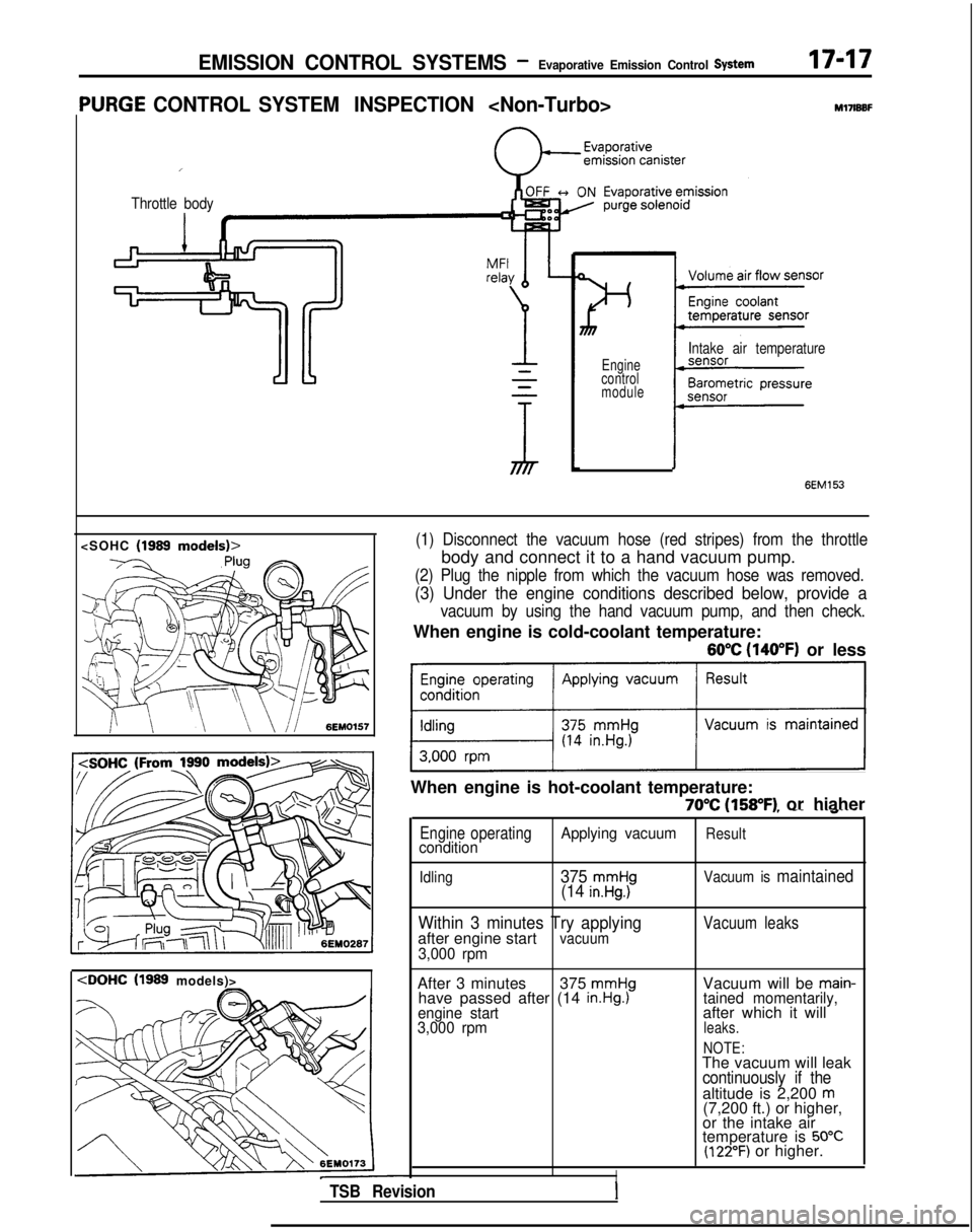
‘URGE CONTROL SYSTEM INSPECTION
I
Throttle body
M17lBBF
Engine
control
module
Intake air temperature
(1999
models)>
6EM153
(1) Disconnect the vacuum hose (red stripes) from the throttle
body and connect it to a hand vacuum pump.
(2) Plug the nipple from which the vacuum hose was removed.
(3) Under the engine conditions described below, provide a
vacuum by using the hand vacuum pump, and then check.
When engine is cold-coolant temperature:
60°C (140°F) or less
~1
When engine is hot-coolant temperature:
70°C (158°F) or hiaher, -- ---~“----
Engine operatingApplying vacuumResultcondition
Idling375 mmHg(14 in.Hg.)Vacuum is maintained
Within 3 minutes Try applyingafter engine startvacuum3,000 rpm
Vacuum leaks
After 3 minutes 375 mmHghave passed after (14 in.Hg.)engine start
3,000 rpm
Vacuum will be main-tained momentarily,after which it willleaks.
NOTE:
The vacuum will leakcontinuously if thealtitude is 2,200 m(7,200 ft.) or higher,
or the intake air
temperature is
50°C(122°F) or higher.
ITSB RevisionI
Page 638 of 1273
EMISSION CONTROL SYSTEMS -Evaporative Emission Control System
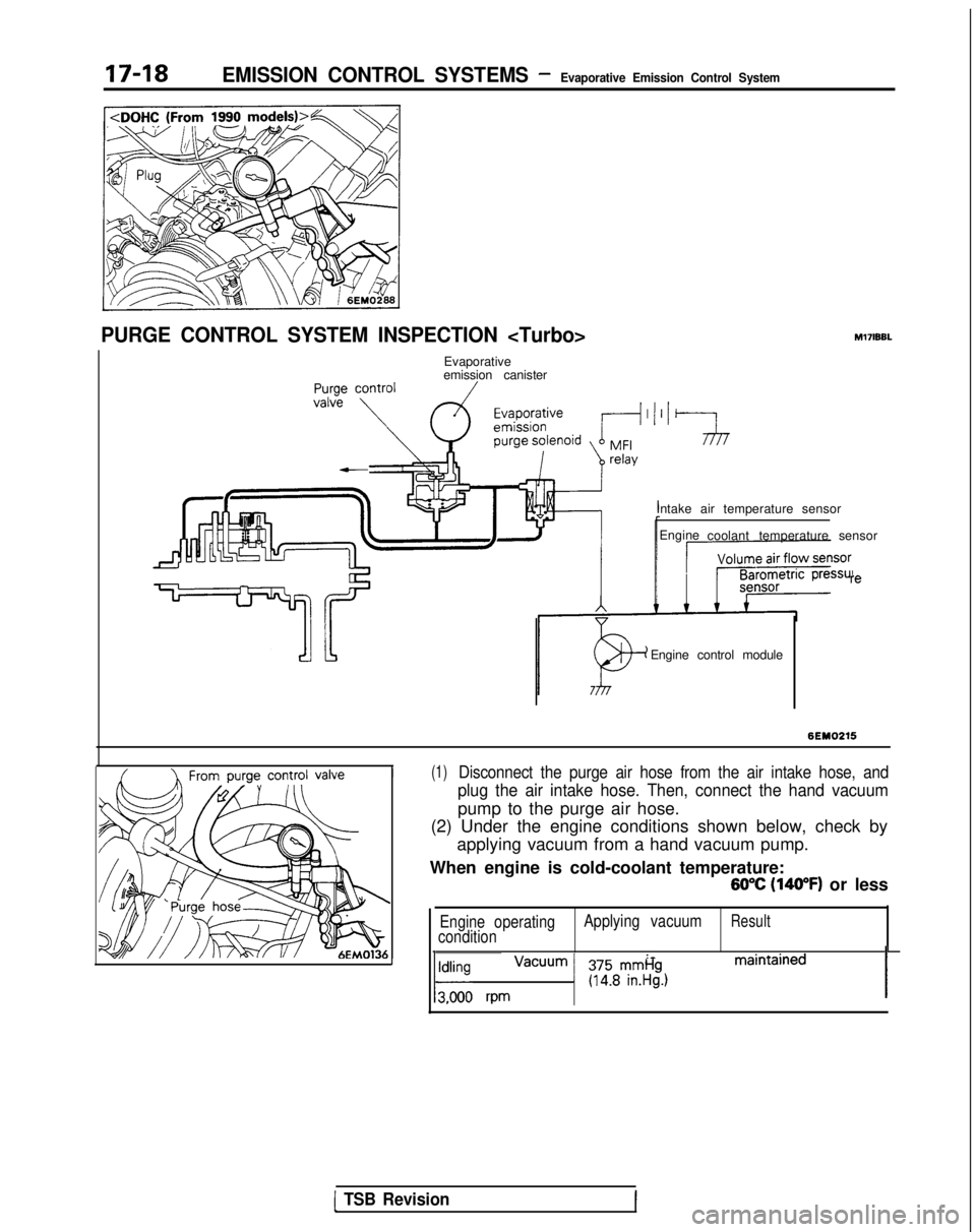
PURGE CONTROL SYSTEM INSPECTION M17lBBL
Evaporative
emission canister
Intake air temperature sensorEngine coolant temperature sensor re
Engine control module
I(1)Disconnect the purge air hose from the air intake hose, and
plug the air intake hose. Then, connect the hand vacuum
pump to the purge air hose.
(2) Under the engine conditions shown below, check by
applying vacuum from a hand vacuum pump.
When engine is cold-coolant temperature:
60°C (140°F) or less
Engine operating Applying vacuumResultcondition
1 vacuum is maintained 1ldldl rpm1 gy?r$y)
[ TSB Revision
Page 639 of 1273
EMISSION CONTROL SYSTEMS -Evaporative Emission Control System17-19
When engine is hot-coolant temperature:
70% (158°F) or higher
Engine operating
condition Applying vacuumResult
Idling
Vacuum is maintained
3,000 rpm withinTry applyingthree minutes after vacuumstarting engine
Vacuum leaks
3,000 rpm after
three minutes
have elapsedafter startingengine
375 mmHg(14.8 in.Hg.1Vacuum will be main-tained momentarily,after which it willleaks.
NOTE
The vacuum will leak
continuously if the
altitude is 2,200
m(7,200 ft.) or higher,
or the intake air
temperature is
50°C(122°F) or higher.
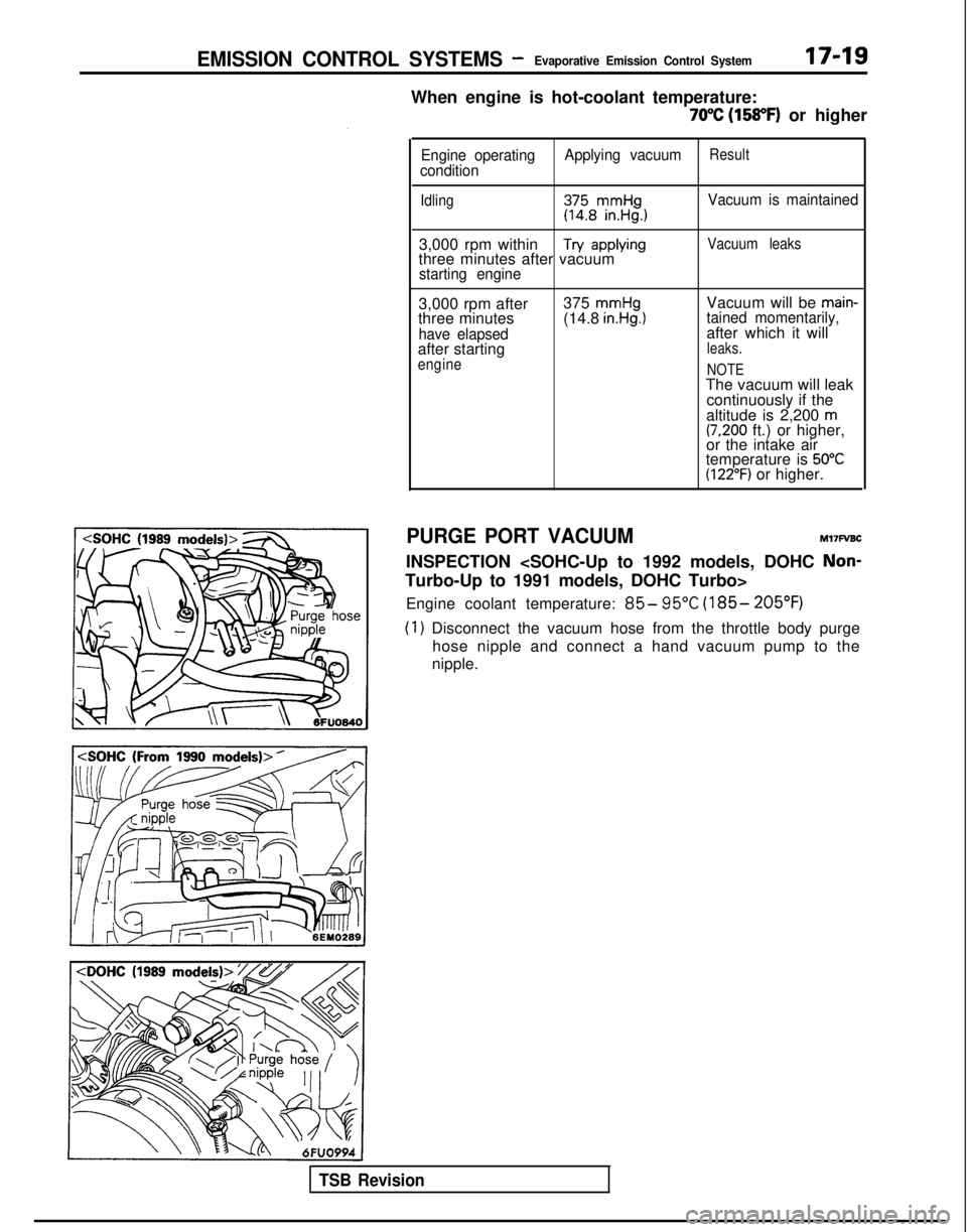
PURGE PORT VACUUM MITFVBC
INSPECTION
Non-
Turbo-Up to 1991 models, DOHC Turbo> Engine coolant temperature:
85- 95°C (185- 205°F)
(1) Disconnect the vacuum hose from the throttle body purge hose nipple and connect a hand vacuum pump to the
nipple.
TSB Revision
Page 640 of 1273
17-20EMISSION CONTROL SYSTEMS -Evaporative Emission Control System
Engine speed (rpm)>
3FU262
E2id>
‘_/- )Engine
speed
(rpm)1 FU446
1 TSB Revision
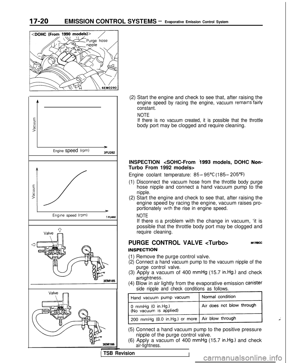
(2) Start the engine and check to see that, after raising the
engine speed by racing the engine, vacuum remains fairly
constant.
NOTE
If there is no vacuum created, it is possible that the throttle
body port may be clogged and require cleaning.
INSPECTION
i993 models, DOHC Non-
Turbo From 1992 models>
Engine coolant temperature: 85- 95°C (185- 205°F)
(1) Disconnect the vacuum hose from the throttle body purge
hose nipple and connect a hand vacuum pump to the
nipple.
(2) Start the engine and check to see that, after raising the engine speed by racing the engine, vacuum raises pro-
portionately with the rise in engine speed.
NOTE
If there IS a problem with the change in vacuum, ‘it is
possible that the throttle body port may be clogged and
require cleaning.
PURGE CONTROL VALVE
INSPECTION
Ml7B.X
(1) Remove the purge control valve.
(2) Connect a hand vacuum pump to the vacuum nipple of the
purge control valve.
(3) Apply a vacuum of 400 mmHg (15.7 in.Hg.) and check
airtightness.
(4) Blow in air lightly from the evaporative emission Canister
side nipple and check conditions as follows.
(5) Connect a hand vacuum pump to the positive pressure
nipple of the purge control valve.
(6) Apply a vacuum of 400
mmHg (15.7 in.Hg.) and check
air-tightness.
I
Trending: oil viscosity, battery replacement, washer fluid, clutch, wheel size, radio, turn signal bulb
