MITSUBISHI GALANT 1989 Service Repair Manual
Manufacturer: MITSUBISHI, Model Year: 1989, Model line: GALANT, Model: MITSUBISHI GALANT 1989Pages: 1273, PDF Size: 37.62 MB
Page 621 of 1273
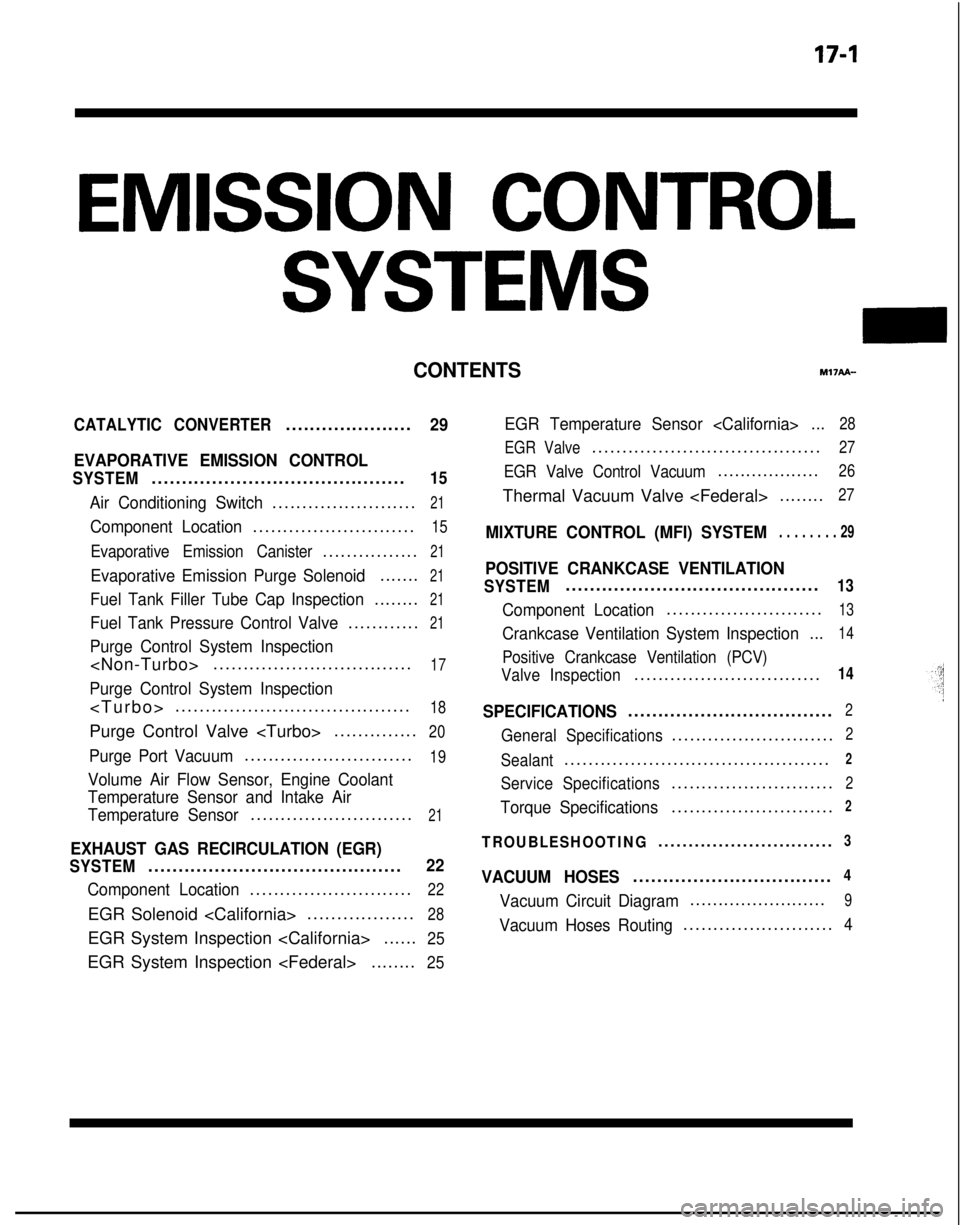
EMISSION CONTROL
SYSTEMS
CONTENTSr.w?API-
CATALYTIC CONVERTER.....................29
EVAPORATIVE EMISSION CONTROL
SYSTEM..........................................15
Air Conditioning Switch........................21
Component Location...........................15
Evaporative Emission Canister................21
Evaporative Emission Purge Solenoid.......21
Fuel Tank Filler Tube Cap Inspection........21
Fuel Tank Pressure Control Valve............21
Purge Control System Inspection
Purge Control System Inspection
.......................................
18
Purge Control Valve
..............20
Purge Port Vacuum............................19
Volume Air Flow Sensor, Engine Coolant
Temperature Sensor and Intake Air
Temperature Sensor
...........................21
EXHAUST GAS RECIRCULATION (EGR)
SYSTEM..........................................22
Component Location...........................22
EGR Solenoid
EGR System Inspection
......25
EGR System Inspection
EGR Temperature Sensor
EGR Valve
......................................27
EGR Valve Control Vacuum..................26
Thermal Vacuum Valve
MIXTURE CONTROL (MFI) SYSTEM. . . . . . . . 29
POSITIVE CRANKCASE VENTILATION
SYSTEM..........................................13
Component Location..........................13
Crankcase Ventilation System Inspection
...14
Positive Crankcase Ventilation (PCV)
Valve Inspection
...............................14
SPECIFICATIONS..................................2
General Specifications...........................2
Sealant............................................2
Service Specifications...........................2
Torque Specifications...........................2
TROUBLESHOOTING.............................3
VACUUM HOSES.................................4
Vacuum Circuit Diagram........................9
Vacuum Hoses Routing.........................4
Page 622 of 1273
17-2EMISSION CONTROL SYSTEMS - Specifications
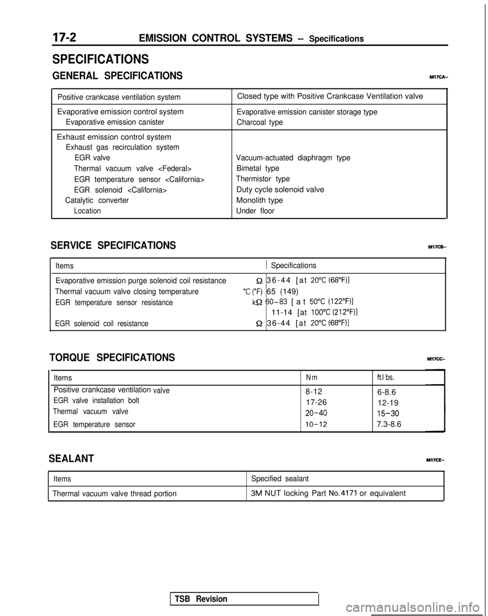
SPECIFICATIONS
GENERAL SPECIFICATIONSMl’IcA-
Positive crankcase ventilation system
Evaporative emission control system
Evaporative emission canister
Exhaust emission control system
Exhaust gas recirculation systemEGR valve
Thermal vacuum valve
EGR temperature sensor
EGR solenoid
Catalytic converter
Location
Closed type with Positive Crankcase Ventilation valve
Evaporative emission canister storage type
Charcoal type
Vacuum-actuated diaphragm type Bimetal type
Thermistor type
Duty cycle solenoid valve
Monolith type
Under floor
SERVICE SPECIFICATIONS M17CB-
Items1 Specifications
Evaporative emission purge solenoid coil resistance
Thermal vacuum valve closing temperature
EGR temperature sensor resistance
Q 36-44 [at 20°C (68”F)I
‘C (“F) 65 (149)
kQ 60-83
[at 50°C (122”F)l
11-14 [at 100°C (212”F)l
EGR solenoid coil resistance52 36-44 [at 20°C (68°F))
TORQUE SPECIFICATIONS
ItemsNmft.1 bs.
Positive crankcase ventilationvalve8-12
6-8.6
EGR valve installation bolt17-2612-19
Thermal vacuum valve20-40 15-30
EGR temperature sensorIO-127.3-8.6
SEALANT
Items
Thermal vacuum valve thread portion
Specified sealant3M NUT locking Part No.4171 or equivalent
TSB Revision
Page 623 of 1273

EMISSION CONTROL SYSTEMS - Troubleshooting17-3
TROUBLESHOOTINGMVEA-
SymptomProbable causeRemedy
Engine will not start or hardVacuum hose disconnected or Repair or replaceto startdamaged
The EGR valve is not closed. Repair or replace
Malfunction of the evaporativeRepair or replace
emission purge solenoid
Rough idle or engine stalls The EGR valve is not closed.Repair or replace
Vacuum hose disconnected or damaged Repair or replace
Malfunction of the positive crankcaseReplaceventilation valve
Malfunction of the purge control system Check the system; if there is a
problem, check its component parts.
Engine hesitates or poorIcceleration
Zxcessive oil consumption
)oor fuel mileage
Malfunction of the exhaust gasrecirculation system
Positive crankcase ventilation line
clogged
Malfunction of the exhaust gas
recirculation system Check the system; if there is a
problem, check its component parts.
Check positive crankcase ventilation
system
Check the system; if there is a problem,
check its component parts.
TSB Revision
Page 624 of 1273
17-4EMISSION CONTROL SYSTEMS - Vacuum Hoses
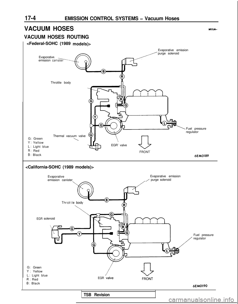
VACUUM HOSES
VACUUM HOSES ROUTING
M17.M-
Evaporative
emission cani*--
Evaporative emission
purge solenoid
Throttle body
G: Green Thermal vacuum valve
\Y : Yellow
L : Light blue
R: Red
B : Black EGR’ valveFRONT
Fuel pressure
regulator
6EM0189
Evaporative Evaporative emission
emission canister
,I purge solenoid
Thr ot t IihR
Y
G: Green
Y:Yellow
L : Light blue
R: Red
B : Black
EGR \alveFRGT
6EM0190
TSB Revision
EGRsolenoid
Fuel pressure
regulator
Page 625 of 1273
EMISSION CONTROL SYSTEMS - Vacuum Hoses17-5
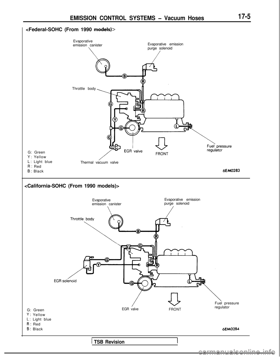
Evaporative
emission canister
\
Evaporative emission
purge solenoid
/
G: Green
Y : Yellow
L : Light blue
R: Red
B : Black Throttle body
Thermal vacuum valve6EM0283
emission canister Evaporative emission
purge solenoid
G: Green
Y : YellowL : Light blue
R: Red
B : Black
EGR valve FRONT
Fuel pressure
regulator
6EM0284
1 TSB Revision
Page 626 of 1273
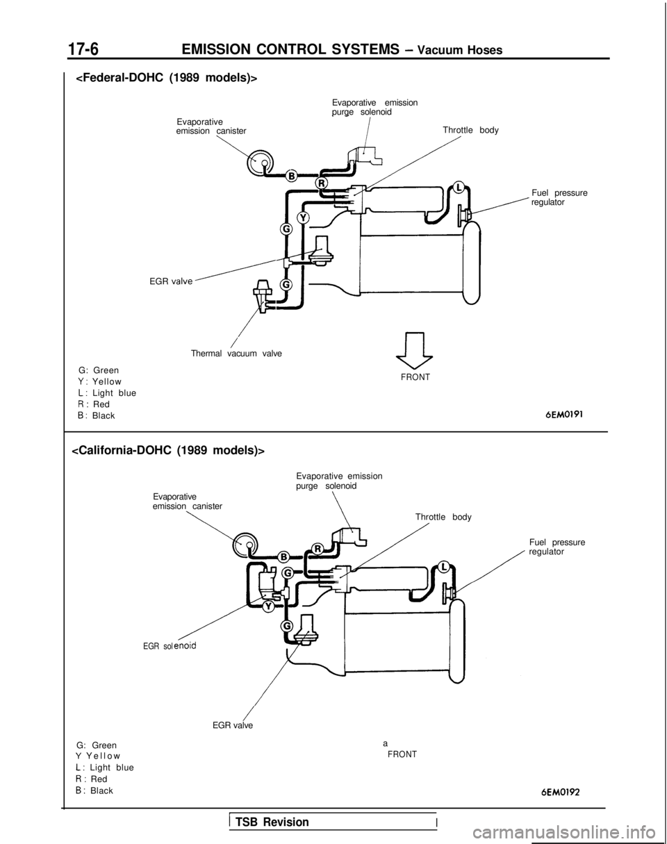
17-6EMISSION CONTROL SYSTEMS - Vacuum Hoses
purge solenoid
Evaporative
emission canister
EGR
valve/
F
Throttle body
/Thermal vacuum valve
G: Green
Y : Yellow
L : Light blue
R: Red
B : Black Fuel pressure
regulator
aFRONT 6EM0191
Evaporative
emission canister
\
Evaporative emission
purge solenoid
\Throttle body
EGR sol
G: GreenY Yello
w
L : Light blue
R: Red
B : Black
/EGR valve
a
FRONT
Fuel pressure
regulator
6EM0192
1 TSB RevisionI
Page 627 of 1273
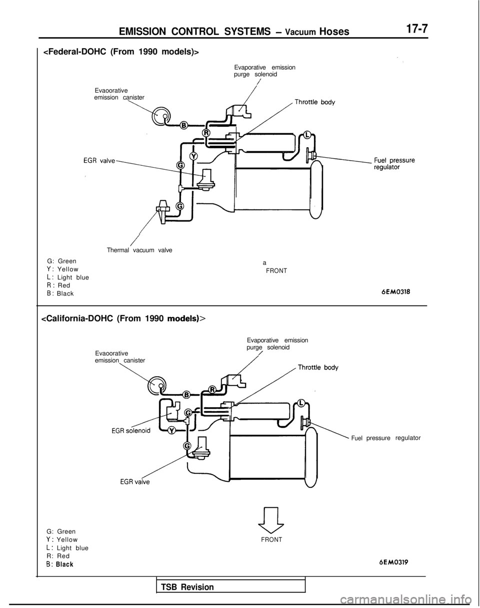
EMISSION CONTROL SYSTEMS - Vacuum Hoses17-7
purge solenoid
/
Evaoorative
emission canister
G: Green
Y : Yellow
L : Light blue
R: Red
B : Black
/Thermal vacuum valve a
FRONT
6EM0318
Evaporative emission
Evaoorative purge solenoid
/emission canister
Fuelpressure
regulator
a
FRONT
6EM0319
G: Green
Y : Yellow
L : Light blue
R: Red
B : Black
TSB Revision
Page 628 of 1273
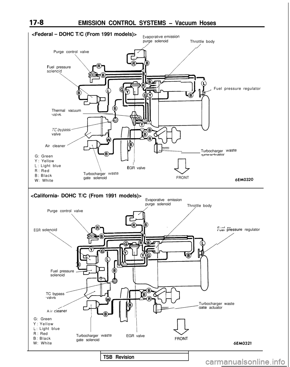
17-8EMISSION CONTROL SYSTEMS - Vacuum Hoses
purge solenoidThrottle body
//Purge control valve
Fuel pressure
11 “Y, Fuel pressure regulator
Thermal vacuum
UJ-\,~l\,P
I L uypassvalve
Air cleaner
G: Green Y
: YellowIEGR valve
Turbocharger
Wasten-t= 2rt1 r3tor
Turbocharger Waste
gate solenoid
0
L : Light blu
e
R: Re
d
B : Blac
k
W: White
FRONT6EM0320
purge solenoidThrottle body
Purge control valve
\
/
EGRsolenoid\PLregulatorruIil rlessure
/
Fuel pressure
solenoid
Turbocharger waste
/aate actuator
TC bypass
.,4111,n
Air cle&er
-0 FR‘;;NT
6EM0321
G: GreenY
: Yello
w
L : Light blu
e
R: Red
B : Blac
k
W: White Turbocharger
wastegate solenoid
EGR valve
TSB Revision
Page 629 of 1273
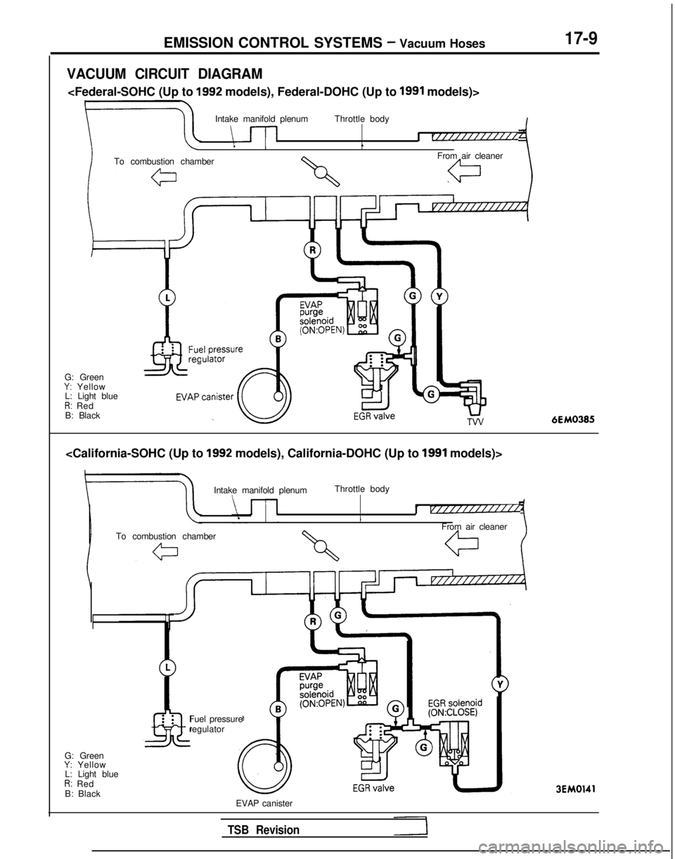
EMISSION CONTROL SYSTEMS - Vacuum Hoses17-9
VACUUM CIRCUIT DIAGRAM
Intake manifold plenum Throttle body
\-l-lI r/////////////L
To combustion chamber From air cleaner
G: Green
Y: Yellow
L: Light blue
R: Red
B: Black
Intake manifold plenum Throttle body
I v///////////l/,
From air cleaner
To combustion chamber
G: Green
Y: Yellow
L: Light blue
R: Red
B: Black Fuel pressure
regulator3EM0141
EVAP canister
TSB Revision
Page 630 of 1273
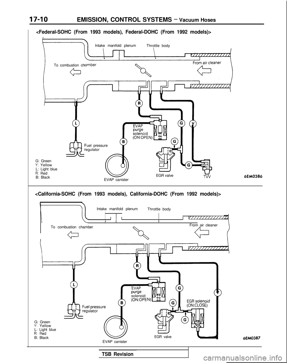
17-10EMISSION, CONTROL SYSTEMS - Vacuum Hoses
Intake manifold plenumThrottle body
To combustion ch
G: Green
Y: Yellow
L: Light blue
R: Red
B: Black Fuel pressure
regulator
EGR valve
EVAP canister6EM0386
Intake manifold plenum Throttle body,
II ) I I v///////i////1
To combustion chamber From air cleaner
I
G: Green
Y: Yellow
L: Light blue
D. 0,.,-dI,. IIC”B: Black pressul
ilatorre
EVAP purge
solenoid (0N:OPE
oil
El
EGR valve6EM0387EVAP canister
TSB Revision