MITSUBISHI GALANT 1989 Service Repair Manual
Manufacturer: MITSUBISHI, Model Year: 1989, Model line: GALANT, Model: MITSUBISHI GALANT 1989Pages: 1273, PDF Size: 37.62 MB
Page 591 of 1273
INTAKE AND EXHAUST - Special Tool/Troubleshooting15-5
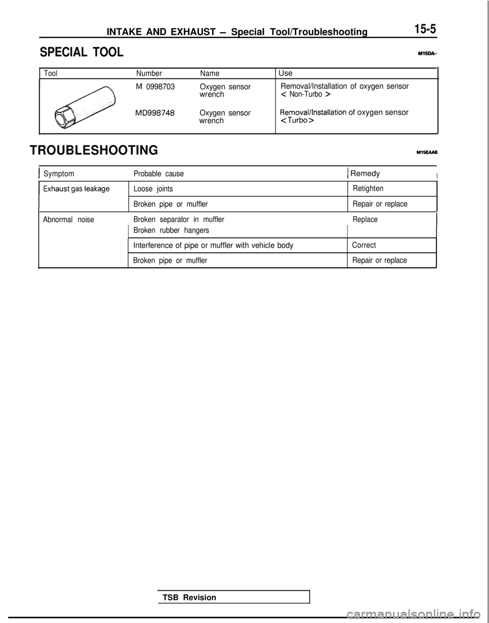
SPECIAL TOOLMlSDA-
ToolNumber
Name1 Use
M 0998703
MD998748Oxygen sensor
wrench
Oxygen sensor
wrench Removal/Installation of oxygen sensor <
Non-Turbo >
Removal/installation of oxygen sensor
TROUBLESHOOTINGYl5EAa8
ISymptom
Probable cause1 RemedyI
Loose joints
Broken pipe or muffler Retighten
Repair or replace
Abnormal noise Broken separator in muffler
Replace
Broken rubber hangers
Interference of pipe or muffler with vehicle body
Broken pipe or muffler Correct
Repair or replace
TSB Revision
Page 592 of 1273
15-6INTAKE AND EXHAUST - Service Adjustment Procedures
SERVICE ADJUSTMENT PROCEDU&$
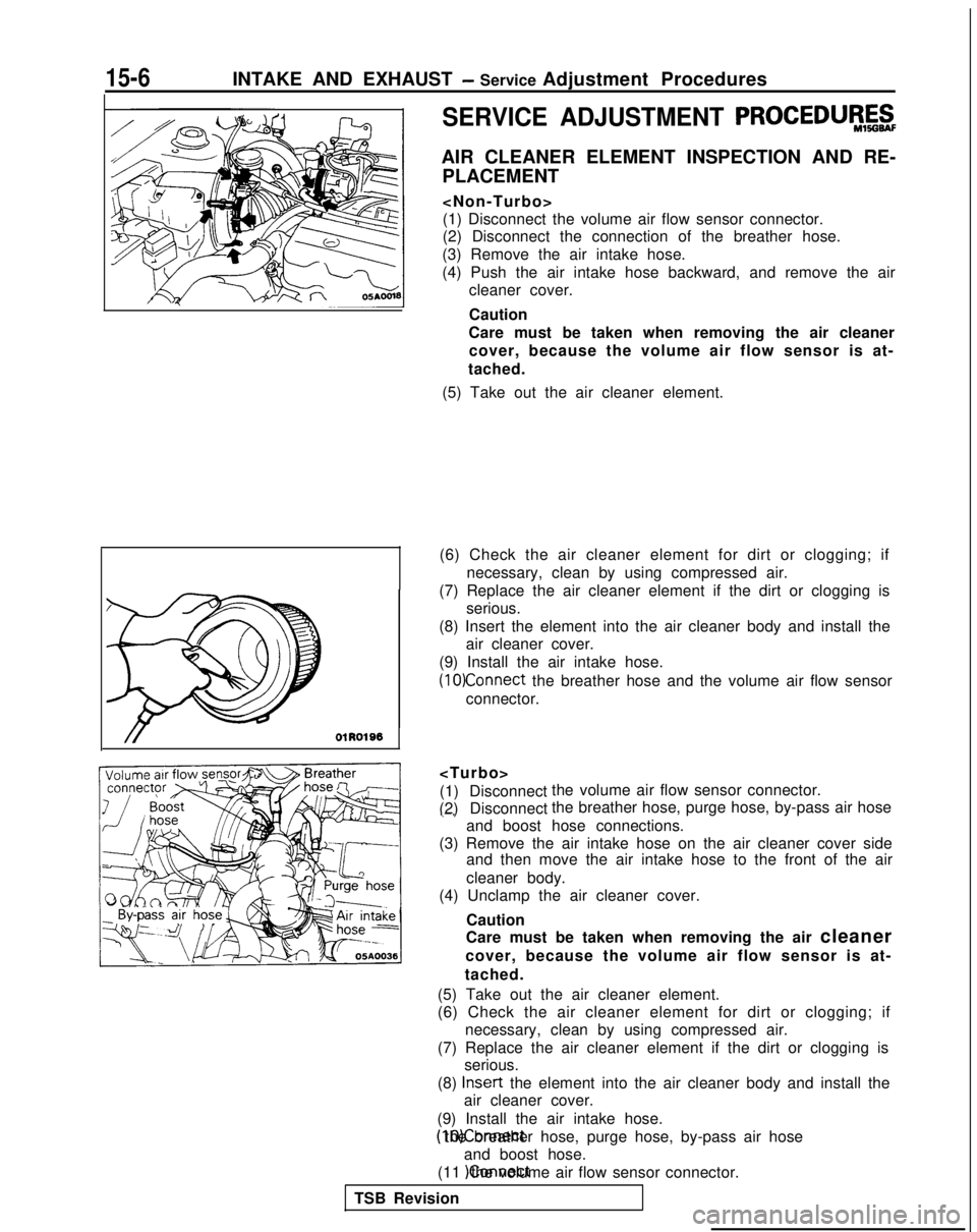
AIR CLEANER ELEMENT INSPECTION AND RE- PLACEMENT
(1) Disconnect the volume air flow sensor connector.
(2) Disconnect the connection of the breather hose.
(3) Remove the air intake hose.
(4) Push the air intake hose backward, and remove the air cleaner cover.
Caution
Care must be taken when removing the air cleaner cover, because the volume air flow sensor is at-
tached.
(5) Take out the air cleaner element.
(6) Check the air cleaner element for dirt or clogging; if necessary, clean by using compressed air.
(7) Replace the air cleaner element if the dirt or clogging is serious.
(8) Insert the element into the air cleaner body and install the air cleaner cover.
(9) Install the air intake hose.
(1O)Connect the breather hose and the volume air flow sensor
connector.
(1) Disconnect
(2) Disconnect the volume air flow sensor connector.
the breather hose, purge hose, by-pass air hose .-.
and boost hose connections.
(3) Remove the air intake hose on the air cleaner cover side and then move the air intake hose to the front of the air
cleaner body.
(4) Unclamp the air cleaner cover.
Caution
Care must be taken when removing the air cleaner
cover, because the volume air flow sensor is at-
tached.
(5) Take out the air cleaner element.
(6) Check the air cleaner element for dirt or clogging; if necessary, clean by using compressed air.
(7) Replace the air cleaner element if the dirt or clogging is serious.
(8) Insert
the element into the air cleaner body and install the
air cleaner cover.
(9) Install the air intake hose. (10)Connect the breather hose, purge hose, by-pass air hose
and boost hose.
(11 )Connect the volume air flow sensor connector.
TSB Revision
Page 593 of 1273
INTAKE AND EXHAUST - Service Adjustment Procedures15-7
Turbocharger waste
gate actuator
05A0150
OSAOlSl
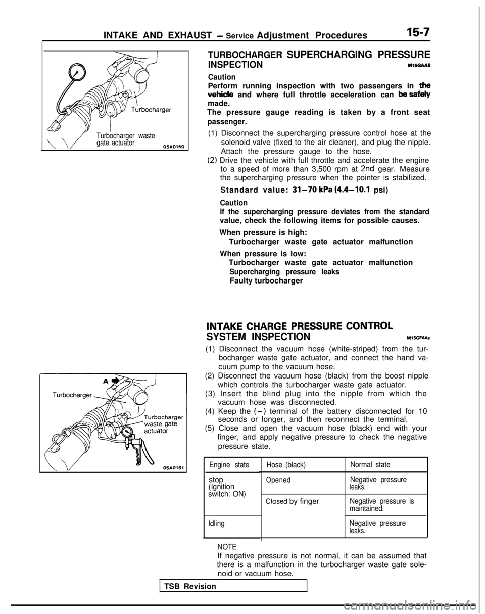
TURBOCHARGER SUPERCHARGING PRESSURE
INSPECTIONM7!%3AAB
Caution
Perform running inspection with two passengers in tha
vehicle and where full throttle acceleration can ba sefely
made.
The pressure gauge reading is taken by a front seat
passenger.
(1) Disconnect the supercharging pressure control hose at the
solenoid valve (fixed to the air cleaner), and plug the nipple.
Attach the pressure gauge to the hose.
(2) Drive the vehicle with full throttle and accelerate the engine to a speed of more than 3,500 rpm at
2nd gear. Measure
the supercharging pressure when the pointer is stabilized.
Standard value:
31-70 kPa (4.4-10.1 psi)
Caution
If the supercharging pressure deviates from the standard
value, check the following items for possible causes.
When pressure is high: Turbocharger waste gate actuator malfunction
When pressure is low: Turbocharger waste gate actuator malfunction
Supercharging pressure leaks
Faulty turbocharger
INTAKECHARGEPRESSURECONTROL
SYSTEM INSPECTION
MlSGFAAa
(1) Disconnect the vacuum hose (white-striped) from the tur- bocharger waste gate actuator, and connect the hand va-
cuum pump to the vacuum hose.
(2) Disconnect the vacuum hose (black) from the boost nipple which controls the turbocharger waste gate actuator.
(3) Insert the blind plug into the nipple from which the vacuum hose was disconnected.
(4) Keep the
(-) terminal of the battery disconnected for 10
seconds or longer, and then reconnect the terminal.
(5) Close and open the vacuum hose (black) end with your
finger, and apply negative pressure to check the negative
pressure state.
Engine state
stop(Ignition
switch: ON)
Idling Hose (black)
Opened
Normal state
Negative pressure
leaks.
Closed by fingerNegative pressure is
maintained.
Negative pressure
leaks.
NOTE
If negative pressure is not normal, it can be assumed that
there is a malfunction in the turbocharger waste gate sole-
noid or vacuum hose.
TSB Revision
Page 594 of 1273
15-8INTAKE AND EXHAUST - Service Adjustment Procedures
u--05A0155
61 N006C
6 I NO056
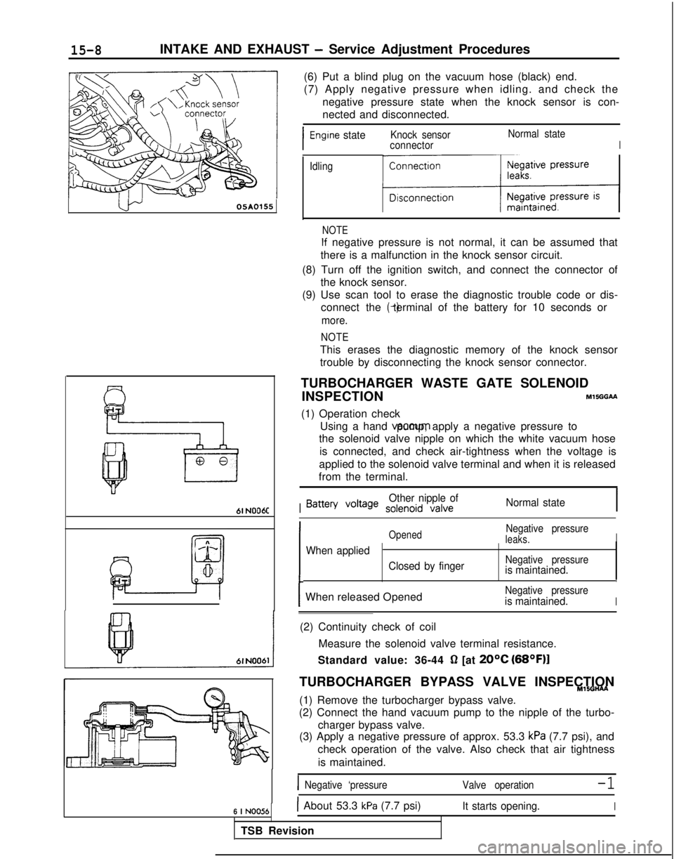
(6) Put a blind plug on the vacuum hose (black) end.
(7) Apply negative pressure when idling. and check thenegative pressure state when the knock sensor is con-
nected and disconnected.
I
Engine stateKnock sensor Normal state
connectorI
Idling
ml
NOTE
If negative pressure is not normal, it can be assumed that
there is a malfunction in the knock sensor circuit.
(8) Turn off the ignition switch, and connect the connector of the knock sensor.
(9) Use scan tool to erase the diagnostic trouble code or dis- connect the (-) terminal of the battery for 10 seconds or
more.
NOTE
This erases the diagnostic memory of the knock sensor
trouble by disconnecting the knock sensor connector.
TURBOCHARGER WASTE GATE SOLENOID INSPECTION
MlSGGM
(1) Operation check Using a hand vaccum pump, apply a negative pressure to
the solenoid valve nipple on which the white vacuum hose
is connected, and check air-tightness when the voltage is
applied to the solenoid valve terminal and when it is released
from the terminal.
I
Other nipple ofBattery Voltage solenoid valveNormal state
OpenedNegative pressureleaks.I
When applied
Closed by fingerNegative pressureis maintained.LIII
Negative pressureis maintained.IIWhen released Opened
(2) Continuity check of coil Measure the solenoid valve terminal resistance.
Standard value: 36-44
0 [at 20°C (68OF)l
TURBOCHARGER BYPASS VALVE INSPECTIONMlSGHAA
(1) Remove the turbocharger bypass valve.
(2) Connect the hand vacuum pump to the nipple of the turbo-
charger bypass valve.
(3) Apply a negative pressure of approx. 53.3
kPa (7.7 psi), and
check operation of the valve. Also check that air tightness
is maintained.
INegative ‘pressure Valve operation-1
IAbout 53.3 kPa (7.7 psi)It starts opening.I
TSB Revision
Page 595 of 1273
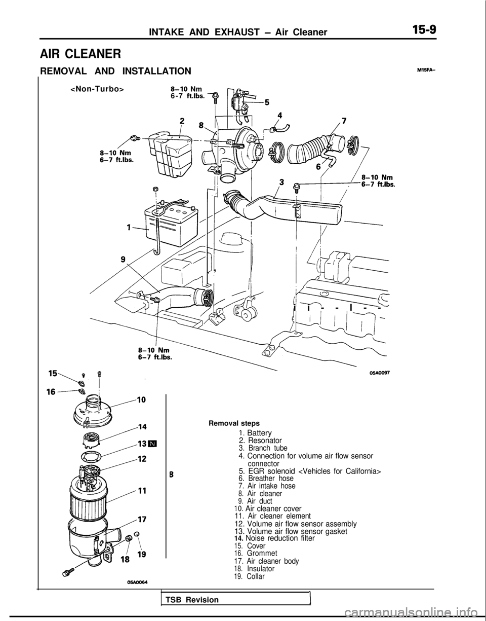
INTAKE AND EXHAUST - Air Cleaner1’5-9
AIR CLEANER
REMOVAL AND INSTALLATIONMlSFA-
6-7 ft.lbs.
IKIII
I
I/I /
I, s;qr
ii--l-
-
05AOO97
Removal steps
1. Battery2. Resonator3. Branch tube4. Connection for volume air flow sensor
B
connector5. EGR solenoid
7. Air intake hose
8.Air cleaner9.Air ductIO. Air cleaner cover11. Air cleaner element12. Volume air flow sensor assembly
13. Volume air flow sensor gasket
14. Noise reduction filter
15.Cover16.Grommet
17. Air cleaner body
18.Insulator19.Collar
TSB RevisionI
Page 596 of 1273
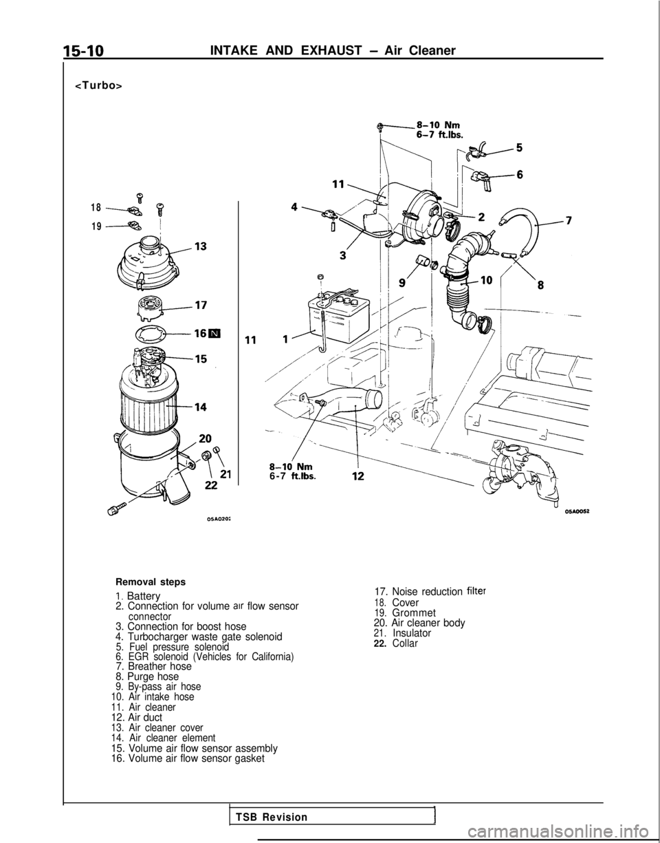
15-10INTAKE AND EXHAUST - Air Cleaner
~8-10 Nm
K nlbF+5
18 19
!\/ ~2%6
Td4fba5-9 /z-l
8-k Nm6-7 ft.lbs.
Removal steps
I. Battery2. Connection for volume arr flow sensorconnector3. Connection for boost hose
4. Turbocharger waste gate solenoid
5. Fuel pressure solenoid
6. EGR solenoid (Vehicles for California)
7. Breather hose
8. Purge hose
9. By-pass air hose
10. Air intake hose
11. Air cleaner
12. Air duct13. Air cleaner cover
14. Air cleaner element
15. Volume air flow sensor assembly
16. Volume air flow sensor gasket 17. Noise reduction
filter
18.Cover19.Grommet
20. Air cleaner body
21.Insulator
22.Collar
TSB Revision
Page 597 of 1273
INTAKE AND EXHAUST - Air Cleaner15-11
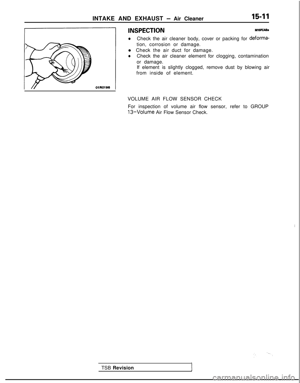
4 'NSPECT'oN
Ml5iCA95
lCheck the air cleaner body, cover or packing for deforma-
1
tion, corrosion or damage.
l Check the air duct for damage.
lCheck the air cleaner element for clogging, contamination
or damage. If element is slightly clogged, remove dust by blowing air
from inside of element.
VOLUME AIR FLOW SENSOR CHECK For inspection of volume air flow sensor, refer to GROUP
13-Volume Air Flow Sensor Check.
TSB Revision
I
Page 598 of 1273
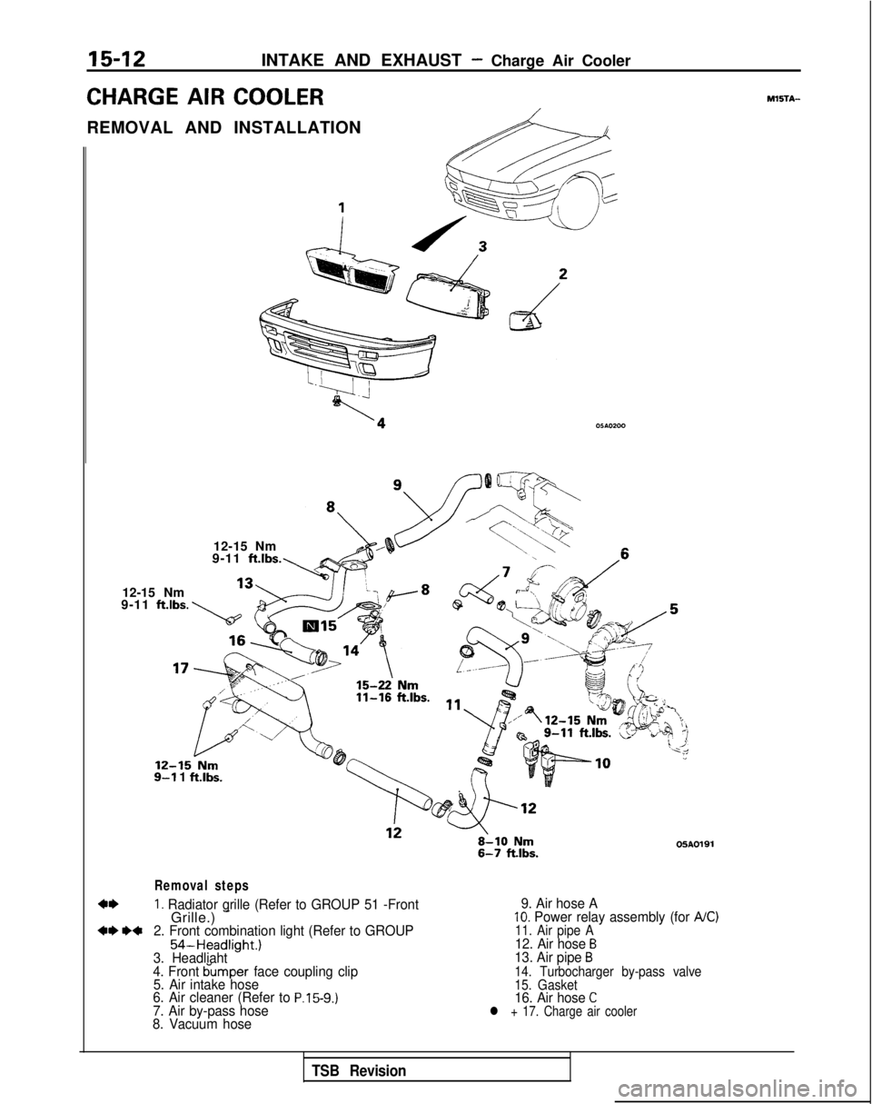
15-12INTAKE AND EXHAUST - Charge Air Cooler
CHARGE AIR COOLER
REMOVAL AND INSTALLATION
A
12-15 Nm&-2-s--
TX.<.\-@
\\’ 19-11 ft.lbs.,_
12-15 Nm
9-11 ftlbs.
12-15-Nm9-l 1 ft.lbs.
05A0191
Removal steps
1. Radiator grille (Refer to GROUP 51 -FrontGrille.) -+e *+2. Front combination light (Refer to GROUP
54-Headlight.)
3. Headliaht
4. Front bumper face coupling clip
5. Air intake hose
6. Air cleaner (Refer to
P.15-9.)7. Air by-pass hose
8. Vacuum hose 9. Air hose A
10. Power relay assembly (for A/C)11. Air pipe A12. Air hose B13. Air pipe B14. Turbocharger by-pass valve
15. Gasket
16. Air hose Cl + 17. Charge air cooler
MXiTA-
TSB Revision
Page 599 of 1273
INTAKE AND EXHAUST - Charge Air Cooler15-13
INSPECTIONMl5lcM
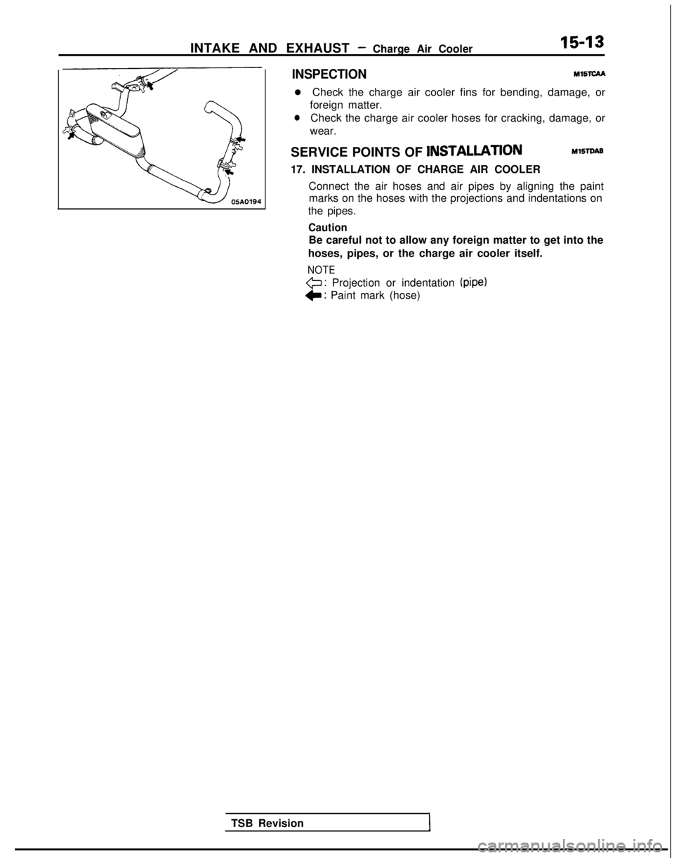
l Check the charge air cooler fins for bending, damage, or
foreign matter.
lCheck the charge air cooler hoses for cracking, damage, or
wear.
SERVICE POINTS OF INSTALLATlON
MlSTDAB
17. INSTALLATION OF CHARGE AIR COOLER
Connect the air hoses and air pipes by aligning the paintmarks on the hoses with the projections and indentations on
the pipes.
Caution
Be careful not to allow any foreign matter to get into the
hoses, pipes, or the charge air cooler itself.
NOTE
<=J : Projection or indentation (pipe)
C : Paint mark (hose)
TSB Revision
Page 600 of 1273
15-14INTAKE AND EXHAUST -Intake Manifold
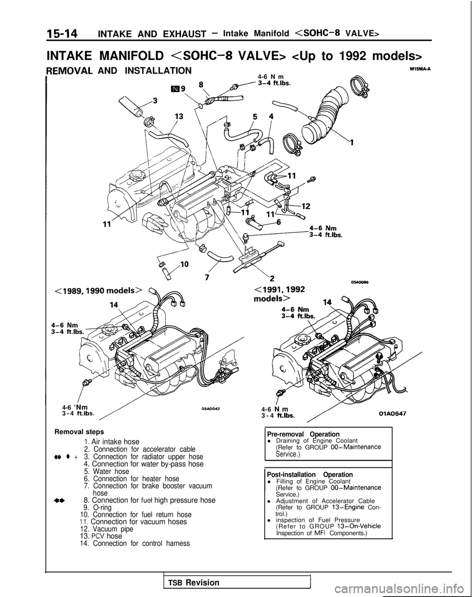
INTAKE MANIFOLD
AND INSTALLATION
4-6 Nm
Y “1 ~/c 3-4 ft.‘bs.At
4-6 ‘Nm
3-4 ft.lbs.
Removal steps
I. Air intake hose2. Connection for accelerator cable+e l +3. Connection for radiator upper hose4. Connection for water by-pass hose5. Water hose
6. Connection for heater hose
7. Connection for brake booster vacuum hose
8. Connection for fuel high pressure hose9. O-ring
10. Connection for fuel return hose
II. Connection for vacuum hoses12. Vacuum pipe13. PCV hose14. Connection for control harness
MlSMA-A
4-6 N
m
3-4
ft.lbs.OlA0647
Pre-removal Operationl Draining of Engine Coolant
(Refer to GROUP 00-MaintenanceService.)
Post-installation Operationl Filling of Engine Coolant(Refer to GROUP 00-MaintenanceService.)
l Adjustment of Accelerator Cable (Refer to GROUP
13-Engine Con-
trol.)
l inspection of Fuel Pressure
(Refer to GROUP
13-On-VehicleInspection of MFI Components.)
TSB Revision1