MITSUBISHI GALANT 1989 Service Repair Manual
Manufacturer: MITSUBISHI, Model Year: 1989, Model line: GALANT, Model: MITSUBISHI GALANT 1989Pages: 1273, PDF Size: 37.62 MB
Page 581 of 1273
-Wntmr Hncn andWater Pine
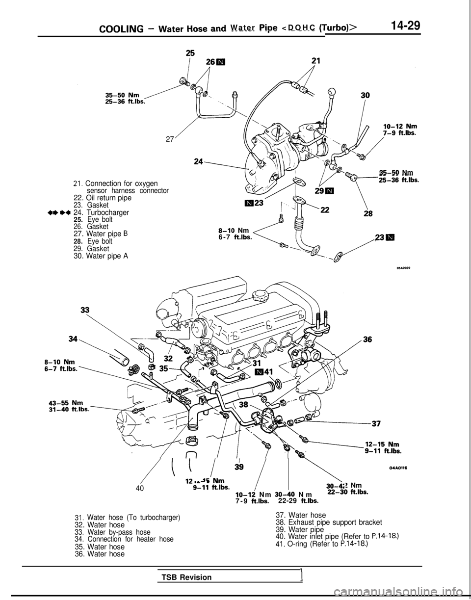
21. Connection for oxygensensor harness connector22. Oil return pipe23.Gasket+, I)+ 24. Turbocharger25.Eye bolt26.Gasket27. Water pipe B28. Eye bolt
29. Gasket
30. Water pipe A27
35-50 Nm
8-10 Nm
6-7 ftlbs.230
/ ’ ,! I,!, ” /40s-i1 ft.lbs.lo-12 Nm 30-40 N
m
22-3t
7-9 ft.lbs.22-29 ft.lbs.
04c.0116
! Nm1 ftlbs.
31. Water hose (To turbocharger)32. Water hose33. Water by-pass hose
34. Connection for heater hose
35. Water hose
36. Water hose
37. Water hose
38. Exhaust pipe support bracket
39. Water pipe
40. Water inlet pipe (Refer to
P.14-18.)41. O-ring (Refer to P.14-18.)
TSB Revision1
Page 582 of 1273
14-30COOLING - Water Hose and Water Pipe
05AOO26
SERVICE POINTS OF REMOVALMWBAG
24. REMOVAL OF TURBOCHARGER ASSEMBLYRemove the turbocharger assembly with the exhaust
fitting, water pipe A, water pipe
B and the oil pipe attached
to it.
INSPECTION
WATER PIPE AND HOSE INSPECTION
Refer to
P.14-23.
Ml4lcAE
SERVICE POINTS OF INSTALLATIONMWDAR
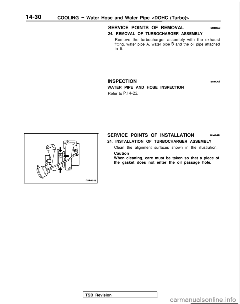
24. INSTALLATION OF TURBOCHARGER ASSEMBLY Clean the alignment surfaces shown in the illustration.
Caution
When cleaning, care must be taken so that a piece of
the gasket does not enter the oil passage hole.
TSB Revision
Page 583 of 1273
COOLING -Engine Coolant Temperature Gauge Unit, Engine CoolantTemoerature Sensor and Engine Coolant Temperature Switch14-31
ENGINE COOLANT TEMPERATURE GAUGE UNIT, ENGINE COOLANT
TEMPERATURE SENSOR AND ENGINE COOLANT TEMPERATURE
SWITCHM14oE-
REMOVAL AND INSTALLATION
Nm/
gine Coolantlo-14 Nm(Refer to GROUP 00-Maintenance8-10 ft.lbs.Service.)
/ I r lcoolo
Sealant: 3M ATD Part No.8660or equivalent04A0118
10 12 Nrny~~~~~7-9 ft.lbs. 2
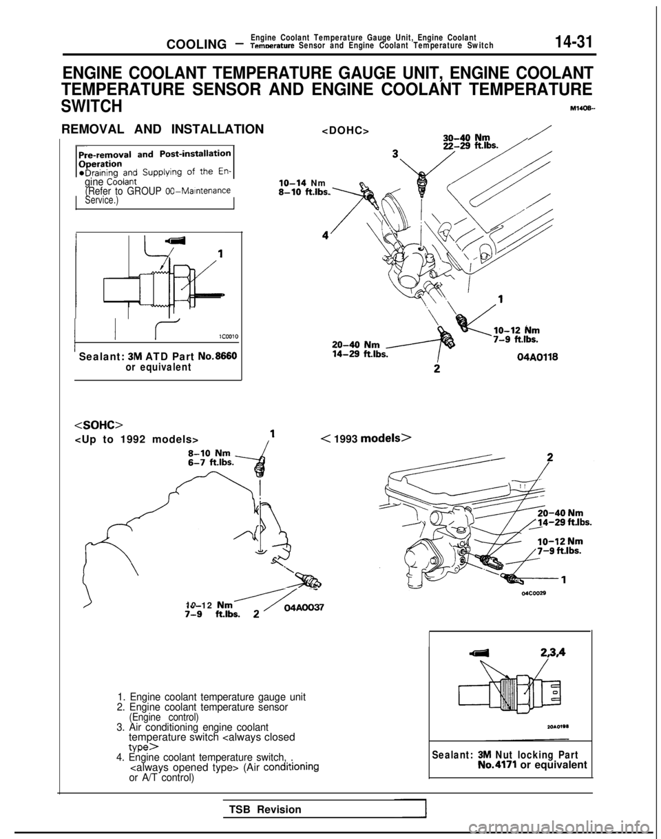
1. Engine coolant temperature gauge unit
2. Engine coolant temperature sensor
(Engine control)3. Air conditioning engine coolanttemperature switch
or A/T control)
Sealant: 3M Nut locking PartNo.4171 or equivalent
TSB Revision
Page 584 of 1273
14-32COOLING -Engine Coolant Temperature Gauge Unit, Engine Coolant
Temperature Sensor and Engine Coolant Temperature Switch
/
Sensor
J
046003
3
04GOO32
9FUO156
---
--I ‘Oi
l
QQQQQQ2cmn99
INSPECTIONM14OOAM
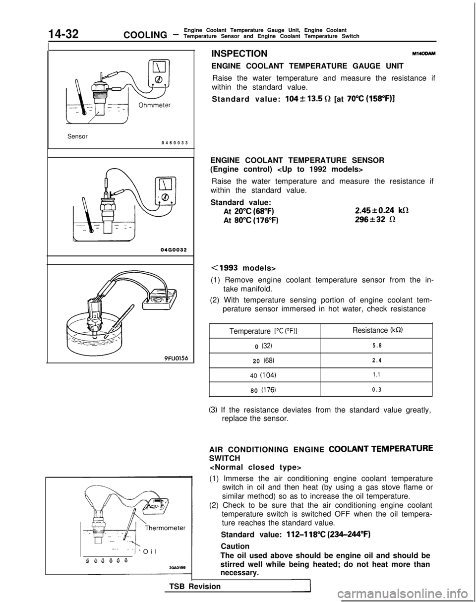
ENGINE COOLANT TEMPERATURE GAUGE UNIT
Raise the water temperature and measure the resistance if
within the standard value.
Standard value:
104k13.5 Q [at 70°C (158”F)]
ENGINE COOLANT TEMPERATURE SENSOR
(Engine control)
Raise the water temperature and measure the resistance if
within the standard value.
Standard value:
At
20°C (68°F)
At 80°C (176°F) 2.4520.24
klR
296232 R
<1993 models>
(1) Remove engine coolant temperature sensor from the in- take manifold.
(2) With temperature sensing portion of engine coolant tem- perature sensor immersed in hot water, check resistance
Temperature 1°C (OF)1Resistance (kR)
0 (32)5.8
20 (68)2.4
40
(I
04)1.1
80 (176)0.3
(3) If the resistance deviates from the standard value greatly,
replace the sensor.
AIR CONDITIONING ENGINE
COOLANT TEMPERATURE
SWITCH
(1) Immerse the air conditioning engine coolant temperature switch in oil and then heat (by using a gas stove flame or
similar method) so as to increase the oil temperature.
(2) Check to be sure that the air conditioning engine coolant temperature switch is switched OFF when the oil tempera-ture reaches the standard value.
Standard value:
112-l 18°C (234-244°F)
Caution
The oil used above should be engine oil and should be
stirred well while being heated; do not heat more than
necessary.
TSB Revision
Page 585 of 1273
COOLING -Engine Coolant Temperature Gauge Unit, Engine Coolant
Temperature Sensor and Engine Coolant Temperature Switch14-33
20R0586
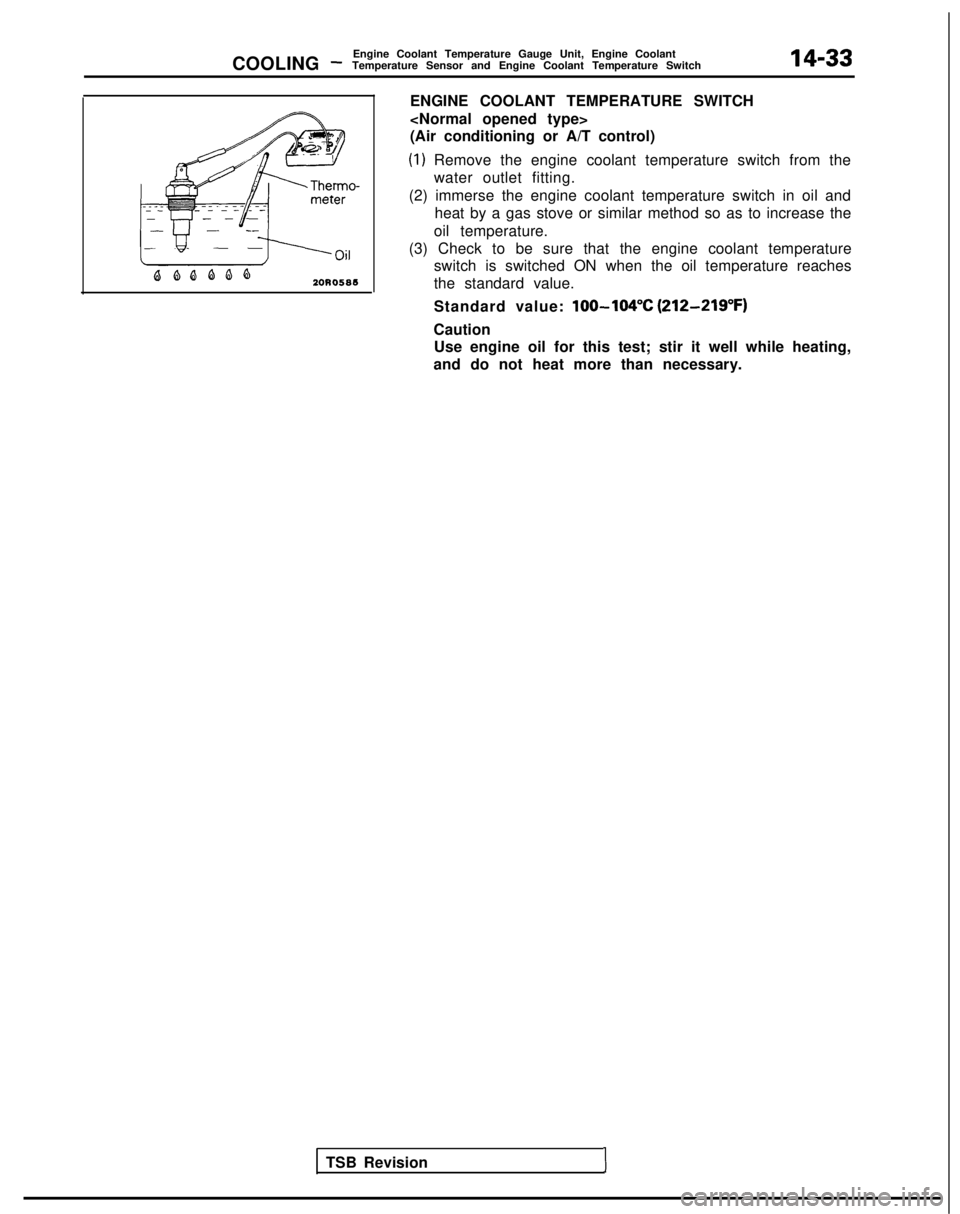
ENGINE COOLANT TEMPERATURE SWITCH
(Air conditioning or A/T control)
(1) Remove the engine coolant temperature switch from the
water outlet fitting.
(2) immerse the engine coolant temperature switch in oil and heat by a gas stove or similar method so as to increase the
oil temperature.
(3) Check to be sure that the engine coolant temperature switch is switched ON when the oil temperature reaches
the standard value.
Standard value:
lOO-104% (212-219°F)
CautionUse engine oil for this test; stir it well while heating,
and do not heat more than necessary.
TSB Revision
1
Page 586 of 1273

NOTES
Page 587 of 1273
15-1
INTAKE AND
EXHAUST
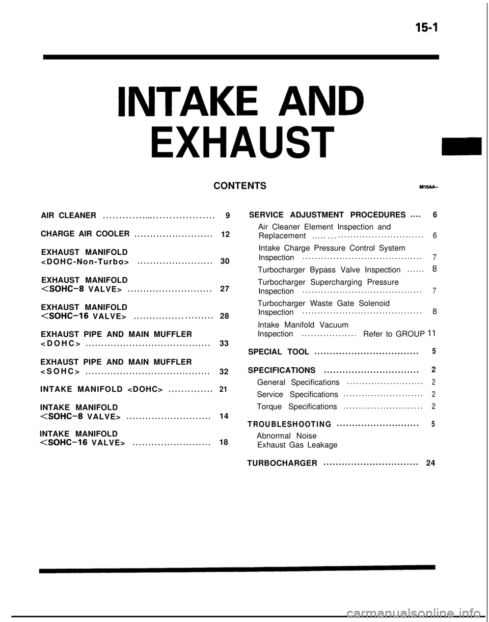
CONTENTSMl!iAn-
AIR CLEANER. . . . . . . . . . . . . a.. . . . . . . . . . . . . . . . . . . .9
CHARGE AIR COOLER
. . . . . . . . . . . . . . . . . . . . . . . . .12
EXHAUST MANIFOLD
. . . . . . . . . . . . . . . . . . . . . . . .30
EXHAUST MANIFOLD
EXHAUST MANIFOLD
EXHAUST PIPE AND MAIN MUFFLER
. . . . . . . . . . . . . . . . . . . . . . . . . . . . . . . . . . . . \
. . . .33
EXHAUST PIPE AND MAIN MUFFLER
. . . . . . . . . . . . . . . . . . . . . . . . . . . . . . . . . . . . \
. . . .32
INTAKE MANIFOLD
. . . . . . . . . . . . . .21
INTAKE MANIFOLD
INTAKE MANIFOLD
(SOHC-16 VALVE>. . . . . . . . . . . . . . . . . . . . . . . . .18 SERVICE ADJUSTMENT PROCEDURES
....
6
Air Cleaner Element Inspection and
Replacement .....
.:............................
.
6
Intake Charge Pressure Control System
Inspection
......................................
.
7
Turbocharger Bypass Valve Inspection
.....
.
8
Turbocharger Supercharging Pressure
Inspection ......................................
.
7
Turbocharger Waste Gate Solenoid
Inspection ......................................
.
8
Intake Manifold Vacuum
Inspection ..................
Refer to GROUP
11
SPECIAL TOOL .................................
.
5
SPECIFICATIONS
..............................
.
2
General Specifications
........................
.
2
Service Specifications
.........................
.
2
Torque Specifications
.........................
.
2
TROUBLESHOOTING...........................5
Abnormal Noise
Exhaust Gas Leakage
TURBOCHARGER ..............................
.
24
Page 588 of 1273
15-2INTAKE AND EXHAUST - Specifications
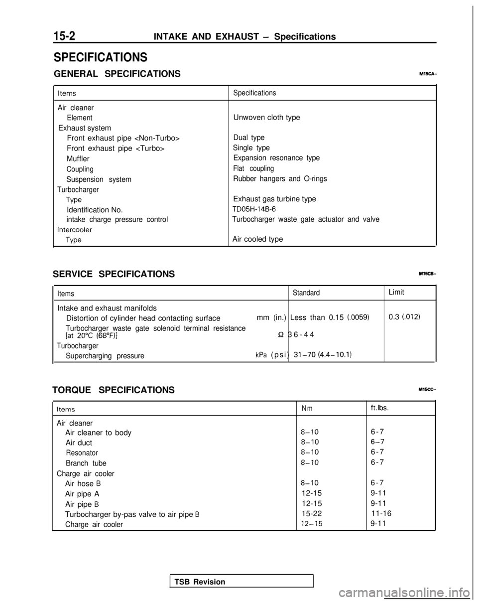
SPECIFICATIONS
GENERAL SPECIFICATIONSMEch-
Items
Air cleaner
Element
Exhaust systemFront exhaust pipe
Front exhaust pipe
Muffler
Coupling
Suspension system
Turbocharger
Type
Identification No.
intake charge pressure control
Intercooler
Type Specifications
Unwoven cloth type
Dual type
Single type Expansion resonance type
Flat coupling
Rubber hangers and O-rings
Exhaust gas turbine type
TD05H-14B-6
Turbocharger waste gate actuator and valve
Air cooled type
SERVICE SPECIFICATIONS
Items
Intake and exhaust manifolds
StandardLimit
Distortion of cylinder head contacting surface mm (in.) Less than 0.15 (0059)0.3 (.012)
Turbocharger waste gate solenoid terminal resistance[at 20°C (68”F)l5-2 36-4
4
Turbocharger
Supercharging pressurekPa (psi) 31-70 (4.4-10.1)
TORQUE SPECIFICATIONS
Items
Air cleaner
Air cleaner to body
Air duct
Resonator
Branch tube
Charge air cooler
Air hose B
Air pipe A Air pipe
B
Turbocharger by-pas valve to air pipe B
Charge air cooler
Nmft.lbs.
8-106-
7
8-106-7
8-106-
7
8-106-
7
8-106-
7
12-15 9-11
12-15 9-11
15-22 11-16 12-15
9-11
TSB Revision
Page 589 of 1273
INTAKE AND EXHAUST - Specifications15-3
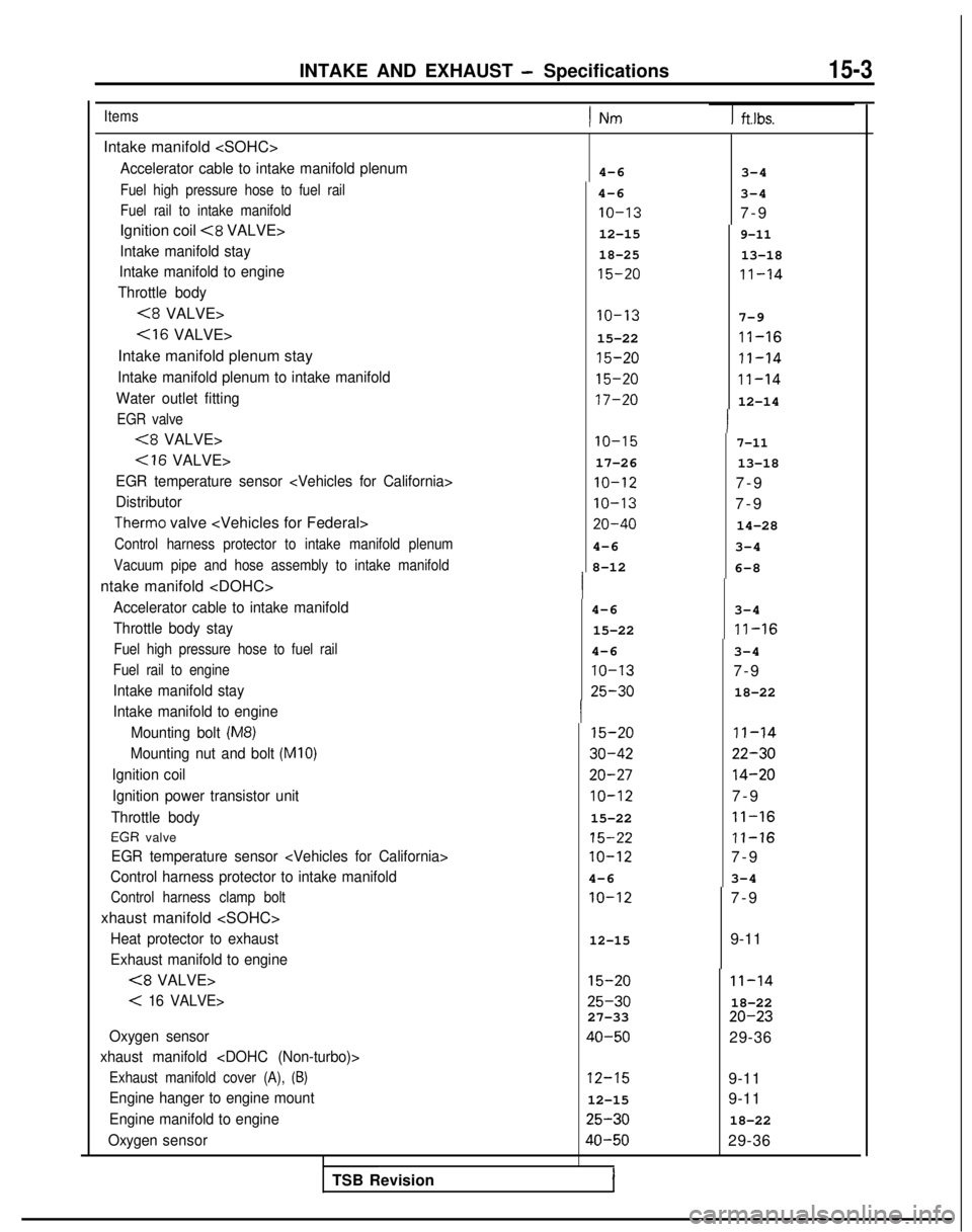
Items) Nm1
ftlbs.
Intake manifold
Accelerator cable to intake manifold plenum
Fuel high pressure hose to fuel rail
Fuel rail to intake manifold
Ignition coil <8 VALVE>
Intake manifold stay
Intake manifold to engine
Throttle body
<8 VALVE>
Intake manifold plenum stay
Intake manifold plenum to intake manifold
Water outlet fitting
EGR valve
(8 VALVE>
Cl6 VALVE>
EGR temperature sensor
Distributor
Therm0 valve
Control harness protector to intake manifold plenum
Vacuum pipe and hose assembly to intake manifold
ntake manifold
Accelerator cable to intake manifold
Throttle body stay
Fuel high pressure hose to fuel rail
Fuel rail to engine
Intake manifold stay
Intake manifold to engine
Mounting bolt
(M8)
Mounting nut and bolt (MIO)
Ignition coilIgnition power transistor unit
Throttle body
EGR valve
EGR temperature sensor
Control harness protector to intake manifold
Control harness clamp bolt
xhaust manifold
Heat protector to exhaust
Exhaust manifold to engine
(8 VALVE>
< 16 VALVE>
Oxygen sensor
xhaust manifold
Exhaust manifold cover (A), (8)
Engine hanger to engine mount
Engine manifold to engine
Oxygen sensor
4-6
4-6 IO-13
12-15
18-25
15-20
3-4
3-4
7-
9
9-11
13-18
11-14
IO-13
7-9
15-22 II-16
15-20
II-14
15-20
11-14
17-20
12-14 IO-15
7-11
17-26
13-18 IO-12
7-9 IO-13
7-9 20-40
14-28
4-6 3-4
8-12 6-8
4-6 3-4
15-22 II-16
4-6 3-4 IO-13
7-9 25-30
18-22 15-20
30-42
20-27
IO-12
15-22
15-22
IO-12
4-6 IO-12 II-14
22-30
14-20
7-9 11-16
11-16
7-9
3-4
12-15
7-
9
9-11 15-20 11-14
25-30
18-22
27-33 20-23
40-50
29-36
12-159-11
12-15 9-11 25-30
18-22 40-50
29-36
TSB Revision
I
Page 590 of 1273
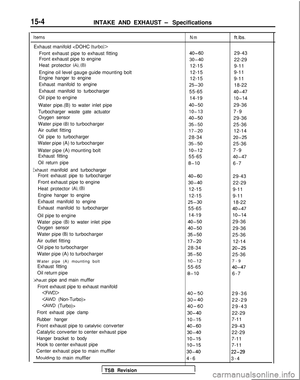
15-4INTAKE AND EXHAUST - Specifications
Items
Exhaust manifold
Front exhaust pipe to exhaust fitting
Front exhaust pipe to engine
Heat protector
(A), (B)
Engine oil level gauge guide mounting bolt
Engine hanger to engine
Exhaust manifold to engine
Exhaust manifold to turbocharger
Oil pipe to engine
Water pipe.(B) to water inlet pipe
Turbocharger waste gate actuator Oxygen sensor
Water pipe (B) to turbocharger
Air outlet fitting
Oil pipe to turbocharger
Water pipe (A) to turbocharger
Water pipe (A) mounting bolt
Exhaust fitting
Oil return pipe
!xhaust manifold and turbocharger
Front exhaust pipe to turbocharger
Front exhaust pipe to engine
Heat protector
(A), (B)
Engine hanger to engine
Exhaust manifold to engine
Exhaust manifold to turbocharger
Oil pipe to engine
Water pipe
(B) to water inlet pipe
Oxygen sensor
Water pipe (B) to turbocharger
Air outlet fitting Oil pipe to turbocharger
Water pipe (A) to turbocharger
W
ater pipe (A) mounting bolt
Exhaust fitting
Oil return pipe
Exhaust pipe and main muffler
Front exhaust pipe to exhaust manifold
Front exhaust pipe clamp
Rubber hanger
Front exhaust pipe to catalytic converter
Catalytic converter to center exhaust pipe
Hanger bracket to body
Hook to center exhaust pipe
Center exhaust pipe to main muffler
Moulding to main muffler
1 TSBRevision
Nm
40-60
30-40
12-15
12-15
12-15
25-30
55-65
14-19
40-50
IO-13
40-50
35-50
17-20
28-34
35-50
IO-12
55-65
8-10
40-60
30-40
12-15
12-15
25-30
55-65
14-19
40-50
40-50
35-50
17-20
28-34
35-50
IO-12
55-65
8-10
40-50
30-40
40-60
30-40
IO-15
40-60
30-40
IO-15
IO-15
30-40
4-
6
1
ft.lbs.
29-43
22-29
9-11
9-11
9-11
18-22
40-47
10-14
29-36
7-
9
29-36
25-36 12-14
20-25
25-36
7-
9
40-47
6-
7
29-43
22-29
9-11
9-11 18-22
40-47
IO-14
29-36
29-36
25-36
12-14
20-25
25-36
7-
9
40-47
6-
7
29-36
22-29
29-43
22-29
7-11
29-43
22-29
7-11
7-11
22-29
3-
4