Side MITSUBISHI LANCER 2005 Workshop Manual
[x] Cancel search | Manufacturer: MITSUBISHI, Model Year: 2005, Model line: LANCER, Model: MITSUBISHI LANCER 2005Pages: 788, PDF Size: 45.98 MB
Page 461 of 788
FOG LAMP
CHASSIS ELECTRICAL54A-73
FOG LAMP
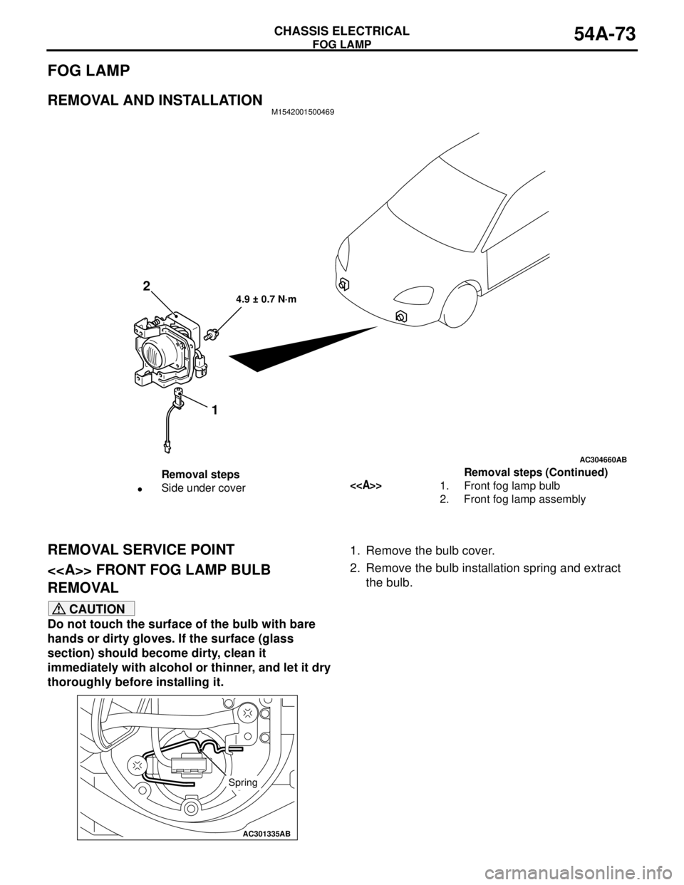
REMOVAL AND INSTALLATIONM1542001500469
REMOVAL SERVICE POINT
<> FRONT FOG LAMP BULB
REMOVAL
CAUTION
Do not touch the surface of the bulb with bare
hands or dirty gloves. If the surface (glass
section) should become dirty, clean it
immediately with alcohol or thinner, and let it dry
thoroughly before installing it.1. Remove the bulb cover.
2. Remove the bulb installation spring and extract
the bulb.
AC304660
4.9 ± 0.7 N·m
AB
2
1
Removal steps
•Side under cover<>1. Front fog lamp bulb
2. Front fog lamp assemblyRemoval steps (Continued)
AC301335AB
Spring
Page 465 of 788
SIDE TURN-SIGNAL LAMP
CHASSIS ELECTRICAL54A-77
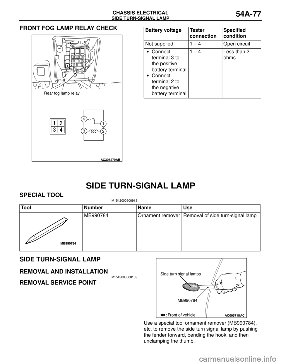
FRONT FOG LAMP RELAY CHECK
SIDE TURN-SIGNAL LAMP
SPECIAL TOOLM1542000600913
SIDE TURN-SIGNAL LAMP
REMOVAL AND INSTALLATIONM1542003300159
REMOVAL SERVICE POINT
Use a special tool ornament remover (MB990784),
etc. to remove the side turn signal lamp by pushing
the fender forward, bending the hook, and then
unclamping the thumb.
AC305279
1 4
3
2
AB
Rear fog lamp relay
Battery voltage Tester
connectionSpecified
condition
Not supplied 1 − 4 Open circuit
•Connect
terminal 3 to
the positive
battery terminal
•Connect
terminal 2 to
the negative
battery terminal1 − 4 Less than 2
ohms
Tool Number Name Use
MB990784 Ornament remover Removal of side turn-signal lamp
MB990784
AC005718
Side turn signal lamps
MB990784
: Front of vehicle
AC
Page 466 of 788
ROOM LAMP
CHASSIS ELECTRICAL54A-78
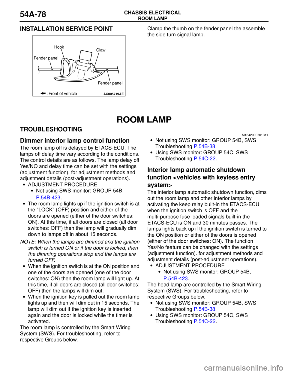
INSTALLATION SERVICE POINTClamp the thumb on the fender panel the assemble
the side turn signal lamp.
ROOM LAMP
TROUBLESHOOTINGM1542000701311
Dimmer interior lamp control function
The room lamp off is delayed by ETACS-ECU. The
lamps off delay time vary according to the conditions.
The control details are as follows. The lamp delay off
Yes/NO and delay time can be set with the settings
(adjustment function). for adjustment methods and
adjustment details (post-adjustment operations).
•ADJUSTMENT PROCEDURE
•Not using SWS monitor: GROUP 54B,
P.54B-423.
•The room lamp lights up if the ignition switch is at
the "LOCK" (OFF) position and either of the
doors are opened (either of the door switches:
ON). At this time, if all doors are closed (all door
switches: OFF) then the lamp will gradually dim
down to lamps off in about 15 seconds.
NOTE: When the lamps are dimmed and the ignition
switch is turned ON or if the door is locked, then
the dimming operations stop and the lamps are
turned OFF.
•When the ignition switch is at the ON position and
one of the doors are opened (one of the door
switches: ON) then the room lamp will light up. At
this time, if all doors are closed (all door switches:
OFF) then the lamps will dim out.
•When the ignition key is pulled out the room lamp
lights up and then will dim out in 15 seconds. The
lamp will dim out if the ignition key is inserted
again and the door is locked while the timer is
activated.
The room lamp is controlled by the Smart Wiring
System (SWS). For troubleshooting, refer to
respective Groups below.•Not using SWS monitor: GROUP 54B, SWS
Troubleshooting P.54B-38.
•Using SWS monitor: GROUP 54C, SWS
Troubleshooting P.54C-22.
Interior lamp automatic shutdown
function
The interior lamp automatic shutdown function, dims
out the room lamp and other interior lamps by
activating the keep relay built-in the ETACS-ECU
when the ignition switch is OFF and the
multi-purpose fuse loaded signals built-in the
ETACS-ECU is ON and 30 minutes passes. The
lamps lights back up if the ignition switch is turned to
the ON position or either of the doors is opened
(either of the door switches: ON). The function
Yes/No feature can be changed with the settings
(adjustment function). for adjustment methods and
adjustment details (post-adjustment operations).
•ADJUSTMENT PROCEDURE
•Not using SWS monitor: GROUP 54B,
P.54B-423.
The head lamp are controlled by the Smart Wiring
System (SWS). For troubleshooting, refer to
respective Groups below.
•Not using SWS monitor: GROUP 54B, SWS
Troubleshooting P.54B-38.
•Using SWS monitor: GROUP 54C, SWS
Troubleshooting P.54C-22.
AC005719
Fender panelHook
Claw
Fender panel
: Front of vehicle
AE
Page 471 of 788
Page 476 of 788
COLUMN SWITCH
CHASSIS ELECTRICAL54A-88
INSPECTIONM1542011200931
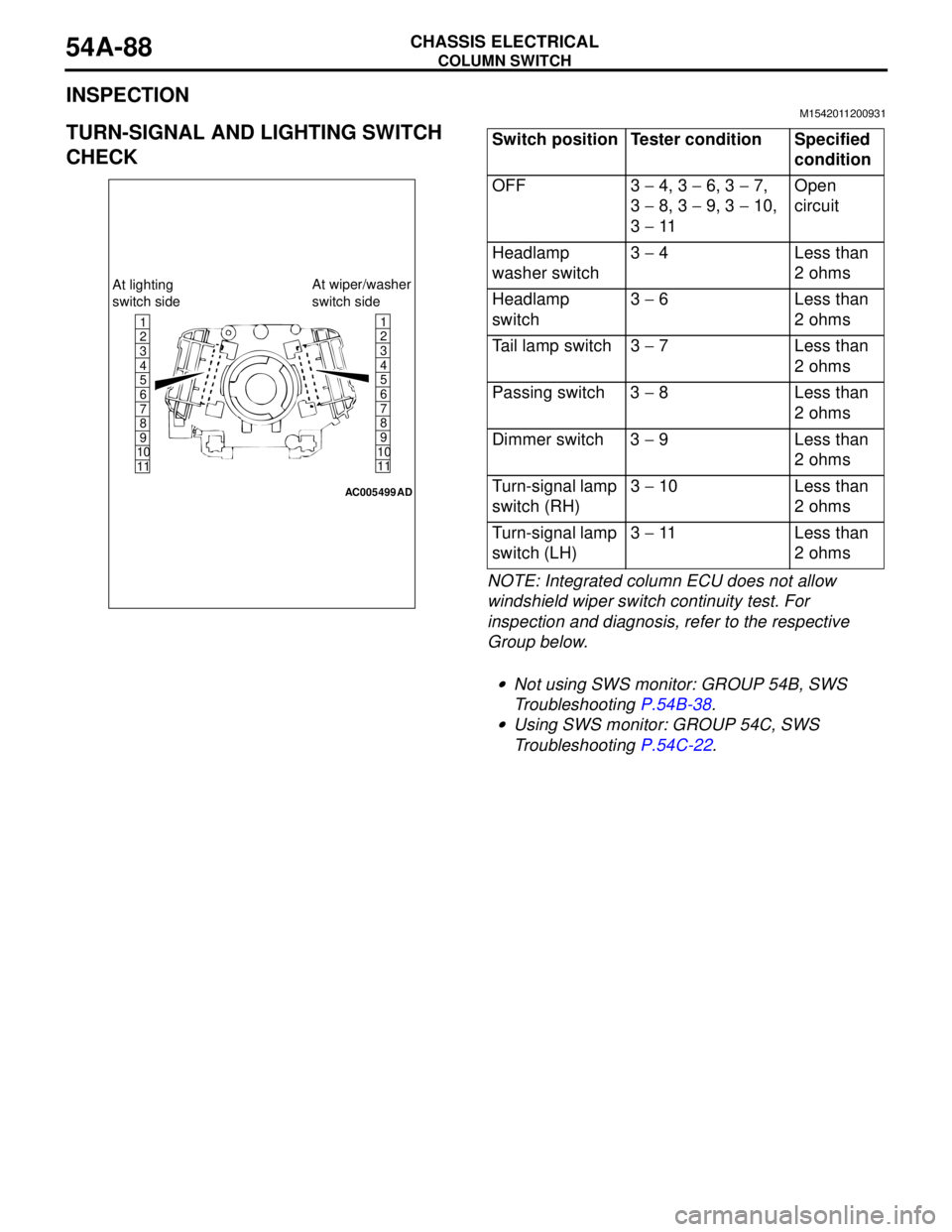
TURN-SIGNAL AND LIGHTING SWITCH
CHECK
NOTE: Integrated column ECU does not allow
windshield wiper switch continuity test. For
inspection and diagnosis, refer to the respective
Group below.
.
•Not using SWS monitor: GROUP 54B, SWS
Troubleshooting P.54B-38.
•Using SWS monitor: GROUP 54C, SWS
Troubleshooting P.54C-22.
1
6
8
11 109 7 5 4 3 21
6
8
11 109 7 5 4
3
2
AC005499
At lighting
switch sideAt wiper/washer
switch side
AD
Switch position Tester condition Specified
condition
OFF 3 − 4, 3 − 6, 3 − 7,
3 − 8, 3 − 9, 3 − 10,
3 − 11Open
circuit
Headlamp
washer switch3 − 4 Less than
2 ohms
Headlamp
switch3 − 6 Less than
2 ohms
Tail lamp switch 3 − 7 Less than
2 ohms
Passing switch 3 − 8 Less than
2 ohms
Dimmer switch 3 − 9 Less than
2 ohms
Turn-signal lamp
switch (RH)3 − 10 Less than
2 ohms
Turn-signal lamp
switch (LH)3 − 11 Less than
2 ohms
Page 486 of 788
55-2
ON-VEHICLE SERVICE . . . . . . . . . . .55-69
SIGHT GLASS REFRIGERANT
LEVEL TEST . . . . . . . . . . . . . . . . . . . . . . . . 55-69
MAGNETIC CLUTCH TEST . . . . . . . . . . . . 55-69
COMPRESSOR DRIVE BELT
ADJUSTMENT . . . . . . . . . . . . . . . . . . . . . . 55-69
DUAL PRESSURE SWITCH CHECK . . . . . 55-69
CHARGING . . . . . . . . . . . . . . . . . . . . . . . . . 55-70
CORRECTING LOW REFRIGERANT LEVEL
IN CASE THE SERVICE CAN IN USED. . . 55-72
DISCHARGING SYSTEM . . . . . . . . . . . . . . 55-72
REFILLING OF OIL IN THE A/C
SYSTEM . . . . . . . . . . . . . . . . . . . . . . . . . . . 55-72
PERFORMANCE TEST . . . . . . . . . . . . . . . 55-73
REFRIGERANT LEAK REPAIR
PROCEDURE . . . . . . . . . . . . . . . . . . . . . . . 55-74
COMPRESSOR NOISE CHECK . . . . . . . . 55-74
POWER RELAY CHECK . . . . . . . . . . . . . . 55-75
IDLE-UP OPERATION CHECK . . . . . . . . . 55-76
CLEAN AIR FILTER REPLACEMENT
PROCEDURE . . . . . . . . . . . . . . . . . . . . . . . 55-76
HEATER CONTROL ASSEMBLY AND A/C
SWITCH . . . . . . . . . . . . . . . . . . . . . . .55-77
REMOVAL AND INSTALLATION . . . . . . . . 55-77
INSPECTION . . . . . . . . . . . . . . . . . . . . . . . 55-79
DISASSEMBLY AND REASSEMBLY . . . . . 55-79
HEATER UNIT, HEATER CORE,
BLOWER ASSEMBLY AND
EVAPORATOR UNIT* . . . . . . . . . . . .55-81
REMOVAL AND INSTALLATION . . . . . . . . 55-81
HEATER UNIT . . . . . . . . . . . . . . . . . . . . . . 55-82
DISASSEMBLY AND REASSEMBLY
DISASSEMBLY AND ASSEMBLY
BLOWER ASSEMBLY . . . . . . . . . . . . . . . . 55-84
DISASSEMBLY AND REASSEMBLY . . . . . 55-84
BLOWERMOTOR, RESISTOR AND
OUTSIDE/INSIDE AIR SELECTION
DAMPER CONTROL MOTOR . . . . . .55-85
REMOVAL AND INSTALLATION . . . . . . . . 55-85
INSPECTION . . . . . . . . . . . . . . . . . . . . . . . . 55-86
EVAPORATOR ASSEMBLY . . . . . . .55-88
REMOVAL AND INSTALLATION
REMOVAL AND INSTALLATION
INSPECTION . . . . . . . . . . . . . . . . . . . . . . . . 55-90
COMPRESSOR ASSEMBLY AND
TENSION PULLEY . . . . . . . . . . . . . . .55-91
REMOVAL AND INSTALLATION . . . . . . . . 55-91
INSPECTION . . . . . . . . . . . . . . . . . . . . . . . . 55-93
DISASSEMBLY AND REASSEMBLY . . . . . 55-94
INSPECTION . . . . . . . . . . . . . . . . . . . . . . . . 55-95
CONDENSER AND CONDENSER
FAN MOTOR . . . . . . . . . . . . . . . . . . . .55-96
REMOVAL AND INSTALLATION . . . . . . . . 55-96
INSPECTION . . . . . . . . . . . . . . . . . . . . . . . . 55-97
REFRIGERANT LINE . . . . . . . . . . . . .55-98
REMOVAL AND INSTALLATION
REMOVAL AND INSTALLATION
DUCTS . . . . . . . . . . . . . . . . . . . . . . . .55-101
REMOVAL AND INSTALLATION . . . . . . . . 55-101
VENTILATORS . . . . . . . . . . . . . . . . . .55-102
REMOVAL AND INSTALLATION . . . . . . . . 55-102
Page 489 of 788
TROUBLESHOOTING
HEATER, AIR CONDITIONER AND VENTILATION55-5
TROUBLESHOOTING
DIAGNOSIS TROUBLESHOOTING FLOWM1552009600364
Refer to GROUP 00, How to Use
Troubleshooting/Inspection Service Points P.00-5.
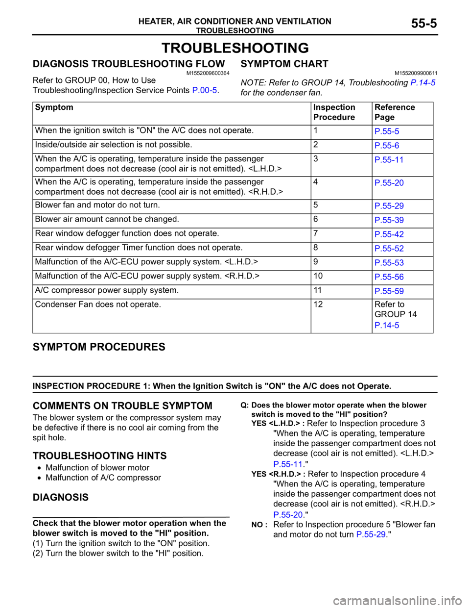
SYMPTOM CHARTM1552009900611
NOTE: Refer to GROUP 14, Troubleshooting P.14-5
for the condenser fan.
SYMPTOM PROCEDURES
INSPECTION PROCEDURE 1: When the Ignition Switch is "ON" the A/C does not Operate.
COMMENTS ON TROUBLE SYMPTOM
The blower system or the compressor system may
be defective if there is no cool air coming from the
spit hole.
TROUBLESHOOTING HINTS
•Malfunction of blower motor
•Malfunction of A/C compressor
DIAGNOSIS
Check that the blower motor operation when the
blower switch is moved to the "HI" position.
(1) Turn the ignition switch to the "ON" position.
(2) Turn the blower switch to the "HI" position.
Q: Does the blower motor operate when the blower
switch is moved to the "HI" position?
YES
Refer to Inspection procedure 3
"When the A/C is operating, temperature
inside the passenger compartment does not
decrease (cool air is not emitted).
P.55-11."
YES
"When the A/C is operating, temperature
inside the passenger compartment does not
decrease (cool air is not emitted).
P.55-20."
NO : Refer to Inspection procedure 5 "Blower fan
and motor do not turn P.55-29." Symptom Inspection
ProcedureReference
Page
When the ignition switch is "ON" the A/C does not operate. 1
P.55-5
Inside/outside air selection is not possible. 2
P.55-6
When the A/C is operating, temperature inside the passenger
compartment does not decrease (cool air is not emitted).
P.55-11
When the A/C is operating, temperature inside the passenger
compartment does not decrease (cool air is not emitted).
P.55-20
Blower fan and motor do not turn. 5
P.55-29
Blower air amount cannot be changed. 6
P.55-39
Rear window defogger function does not operate. 7
P.55-42
Rear window defogger Timer function does not operate. 8
P.55-52
Malfunction of the A/C-ECU power supply system.
P.55-53
Malfunction of the A/C-ECU power supply system.
P.55-56
A/C compressor power supply system. 11
P.55-59
Condenser Fan does not operate. 12 Refer to
GROUP 14
P.14-5
Page 490 of 788
TROUBLESHOOTING
HEATER, AIR CONDITIONER AND VENTILATION55-6
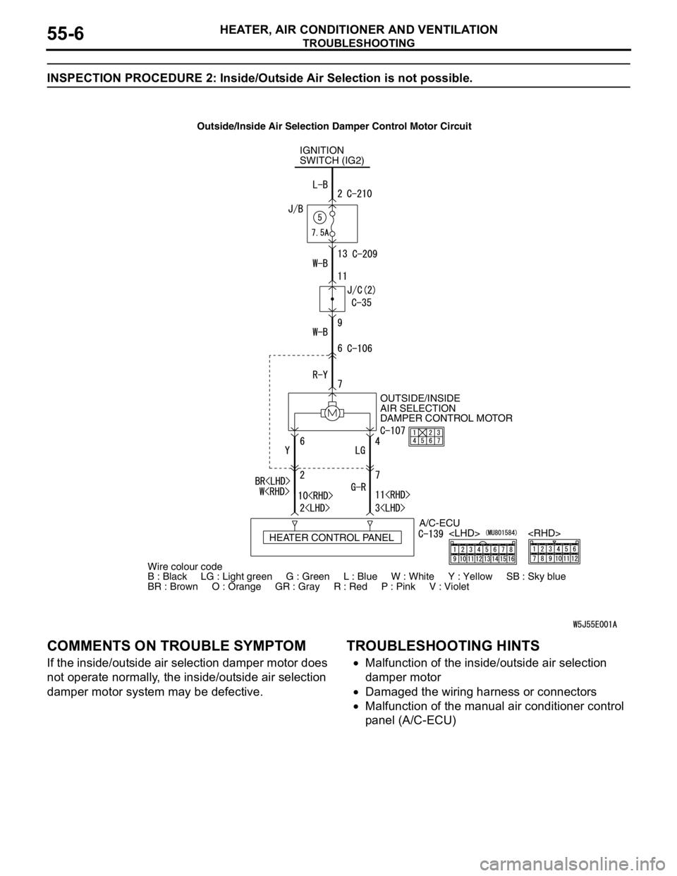
INSPECTION PROCEDURE 2: Inside/Outside Air Selection is not possible.
COMMENTS ON TROUBLE SYMPTOM
If the inside/outside air selection damper motor does
not operate normally, the inside/outside air selection
damper motor system may be defective.
TROUBLESHOOTING HINTS
•Malfunction of the inside/outside air selection
damper motor
•Damaged the wiring harness or connectors
•Malfunction of the manual air conditioner control
panel (A/C-ECU)
IGNITION
SWITCH (IG2)
OUTSIDE/INSIDE
AIR SELECTION
DAMPER CONTROL MOTOR
A/C-ECU
HEATER CONTROL PANEL
Wire colour code
B : Black LG : Light green G : Green L : Blue W : White Y : Yellow SB : Sky blue
BR : Brown O : Orange GR : Gray R : Red P : Pink V : Violet
Outside/Inside Air Selection Damper Control Motor Circuit
Page 491 of 788
TROUBLESHOOTING
HEATER, AIR CONDITIONER AND VENTILATION55-7
DIAGNOSIS
STEP 1. Check the defogger and A/C operations.
Q: Do the defogger and A/C work normally?
YES :
Go to Step 2.
NO
"Malfunction of the A/C-ECU power supply
system
NO
"Malfunction of the A/C-ECU power supply
system
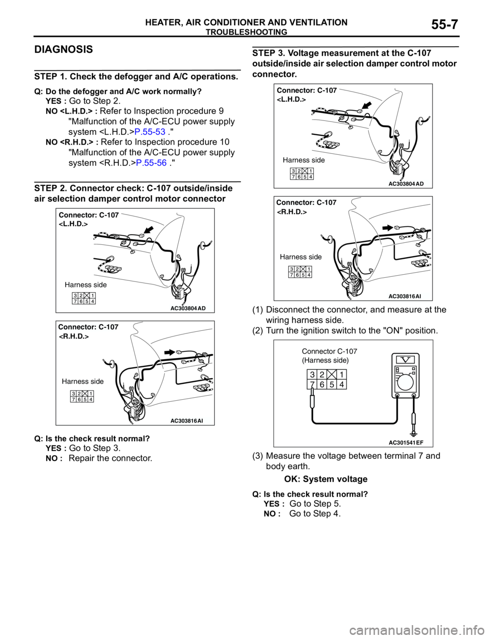
STEP 2. Connector check: C-107 outside/inside
air selection damper control motor connector
Q: Is the check result normal?
YES :
Go to Step 3.
NO : Repair the connector.
STEP 3. Voltage measurement at the C-107
outside/inside air selection damper control motor
connector.
(1) Disconnect the connector, and measure at the
wiring harness side.
(2) Turn the ignition switch to the "ON" position.
(3) Measure the voltage between terminal 7 and
body earth.
OK: System voltage
Q: Is the check result normal?
YES :
Go to Step 5.
NO : Go to Step 4.
AC303804
Connector: C-107
AD
Harness side
AC303816
Connector: C-107
AI
Harness side
AC303804
Connector: C-107
AD
Harness side
AC303816
Connector: C-107
AI
Harness side
AC301541
6 2
7
3
5
4
1
EF
Connector C-107
(Harness side)
Page 492 of 788
TROUBLESHOOTING
HEATER, AIR CONDITIONER AND VENTILATION55-8
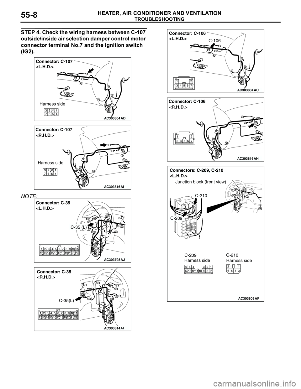
STEP 4. Check the wiring harness between C-107
outside/inside air selection damper control motor
connector terminal No.7 and the ignition switch
(IG2).
NOTE:
AC303804
Connector: C-107
AD
Harness side
AC303816
Connector: C-107
AI
Harness side
AC303798
Connector: C-35
AJ
2 1313 12 1421 105 4616 15 17789
19 18 2011
22
C-35 (L)
AC303814
Connector: C-35
AI
C-35(L)
AC303804
Connector: C-106
AC
C-106
AC303816
Connector: C-106
AH
AC303809
Connectors: C-209, C-210
AF
C-209
C-210
Junction block (front view)
C-209
Harness side
1016
145
12134117 238 9
C-210
Harness side
4 65321