Side MITSUBISHI LANCER 2005 Workshop Manual
[x] Cancel search | Manufacturer: MITSUBISHI, Model Year: 2005, Model line: LANCER, Model: MITSUBISHI LANCER 2005Pages: 788, PDF Size: 45.98 MB
Page 379 of 788
DOOR MIRROR
EXTERIOR51-41
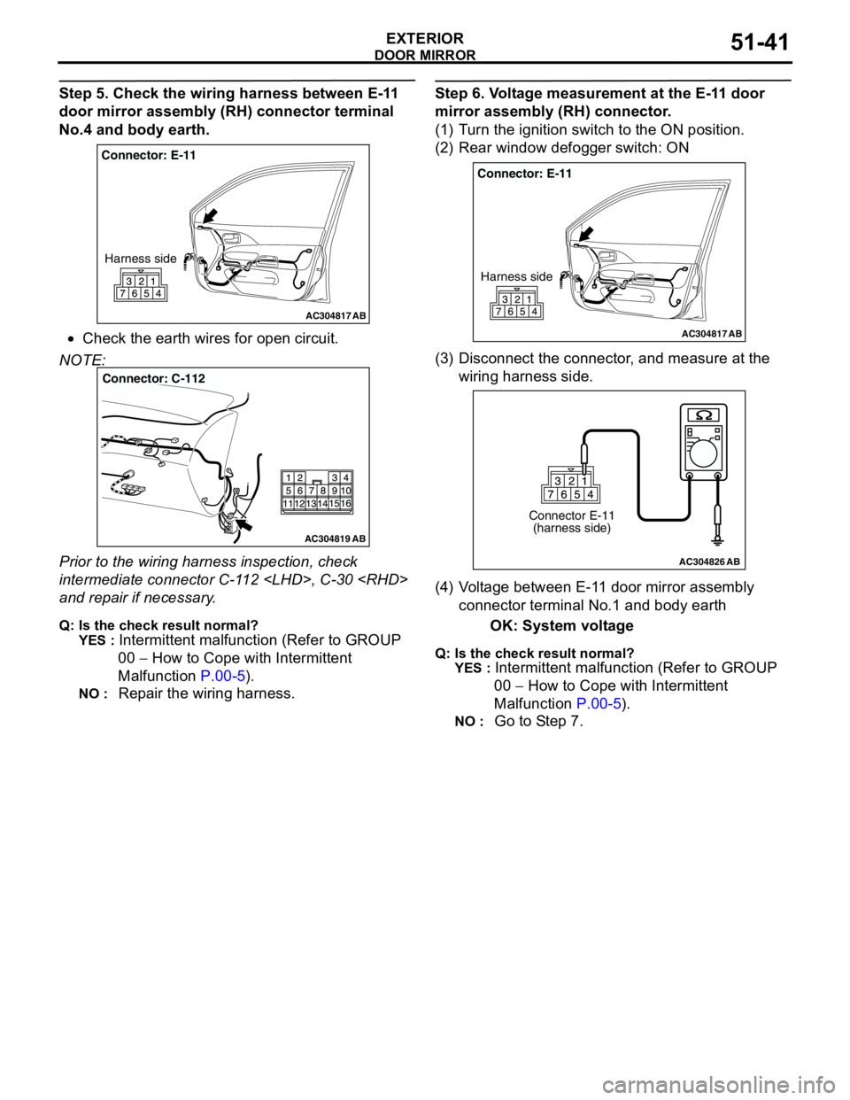
Step 5. Check the wiring harness between E-11
door mirror assembly (RH) connector terminal
No.4 and body earth.
•Check the earth wires for open circuit.
NOTE:
Prior to the wiring harness inspection, check
intermediate connector C-112
and repair if necessary.
Q: Is the check result normal?
YES :
Intermittent malfunction (Refer to GROUP
00 − How to Cope with Intermittent
Malfunction P.00-5).
NO : Repair the wiring harness.
Step 6. Voltage measurement at the E-11 door
mirror assembly (RH) connector.
(1) Turn the ignition switch to the ON position.
(2) Rear window defogger switch: ON
(3) Disconnect the connector, and measure at the
wiring harness side.
(4) Voltage between E-11 door mirror assembly
connector terminal No.1 and body earth
OK: System voltage
Q: Is the check result normal?
YES :
Intermittent malfunction (Refer to GROUP
00 − How to Cope with Intermittent
Malfunction P.00-5).
NO : Go to Step 7.
AC304817
Connector: E-11
Harness side
AB
AC304819
Connector: C-112
AB
AC304817
Connector: E-11
Harness side
AB
AC304826
Connector E-11
(harness side)
AB
Page 380 of 788
DOOR MIRROR
EXTERIOR51-42
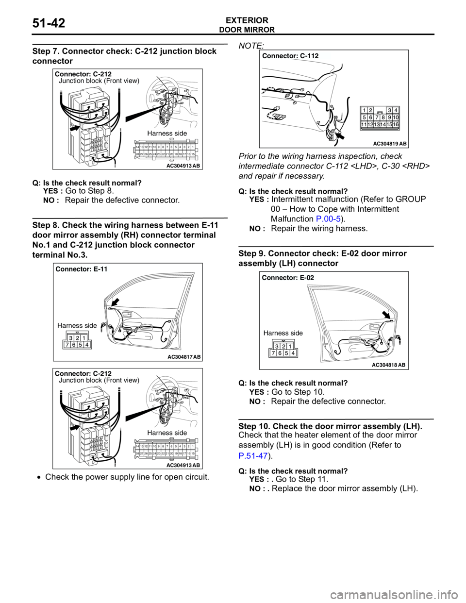
Step 7. Connector check: C-212 junction block
connector
Q: Is the check result normal?
YES :
Go to Step 8.
NO : Repair the defective connector.
Step 8. Check the wiring harness between E-11
door mirror assembly (RH) connector terminal
No.1 and C-212 junction block connector
terminal No.3.
•Check the power supply line for open circuit.NOTE:
Prior to the wiring harness inspection, check
intermediate connector C-112
and repair if necessary.
Q: Is the check result normal?
YES :
Intermittent malfunction (Refer to GROUP
00 − How to Cope with Intermittent
Malfunction P.00-5).
NO : Repair the wiring harness.
Step 9. Connector check: E-02 door mirror
assembly (LH) connector
Q: Is the check result normal?
YES :
Go to Step 10.
NO : Repair the defective connector.
Step 10. Check the door mirror assembly (LH).
Check that the heater element of the door mirror
assembly (LH) is in good condition (Refer to
P.51-47).
Q: Is the check result normal?
YES : .
Go to Step 11.
NO : . Replace the door mirror assembly (LH).
AC304913
21716151718 201912345 623 222425282627981011141213
Connector: C-212
Harness side
AB
Junction block (Front view)
AC304817
Connector: E-11
Harness side
AB
AC304913
21716151718 201912345 623 222425282627981011141213
Connector: C-212
Harness side
AB
Junction block (Front view)
AC304819
Connector: C-112
AB
AC304818
Connector: E-02
Harness side
AB
Page 381 of 788
DOOR MIRROR
EXTERIOR51-43
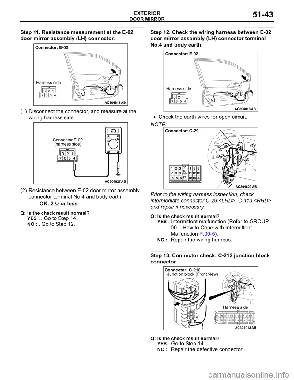
Step 11. Resistance measurement at the E-02
door mirror assembly (LH) connector.
(1) Disconnect the connector, and measure at the
wiring harness side.
(2) Resistance between E-02 door mirror assembly
connector terminal No.4 and body earth
OK: 2 Ω or less
Q: Is the check result normal?
YES : .
Go to Step 14.
NO : . Go to Step 12.
Step 12. Check the wiring harness between E-02
door mirror assembly (LH) connector terminal
No.4 and body earth.
•Check the earth wires for open circuit.
NOTE:
Prior to the wiring harness inspection, check
intermediate connector C-29
and repair if necessary.
Q: Is the check result normal?
YES :
Intermittent malfunction (Refer to GROUP
00 − How to Cope with Intermittent
Malfunction P.00-5).
NO : Repair the wiring harness.
Step 13. Connector check: C-212 junction block
connector
Q: Is the check result normal?
YES :
Go to Step 14.
NO : Repair the defective connector.
AC304818
Connector: E-02
Harness side
AB
AC304827
Connector E-02
(harness side)
AB
AC304818
Connector: E-02
Harness side
AB
AC304820
Connector: C-29
AB
AC304913
21716151718 201912345 623 222425282627981011141213
Connector: C-212
Harness side
AB
Junction block (Front view)
Page 382 of 788
DOOR MIRROR
EXTERIOR51-44
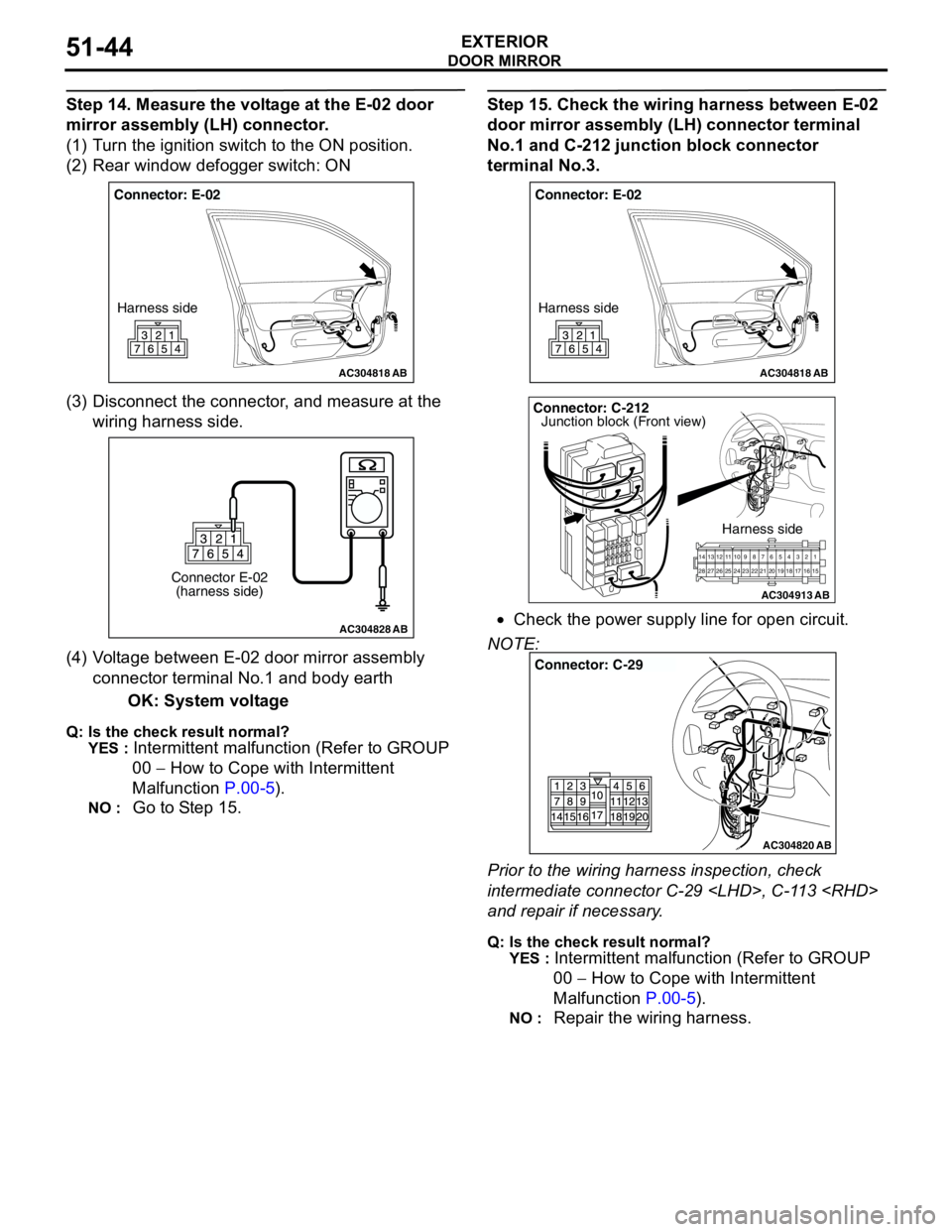
Step 14. Measure the voltage at the E-02 door
mirror assembly (LH) connector.
(1) Turn the ignition switch to the ON position.
(2) Rear window defogger switch: ON
(3) Disconnect the connector, and measure at the
wiring harness side.
(4) Voltage between E-02 door mirror assembly
connector terminal No.1 and body earth
OK: System voltage
Q: Is the check result normal?
YES :
Intermittent malfunction (Refer to GROUP
00 − How to Cope with Intermittent
Malfunction P.00-5).
NO : Go to Step 15.
Step 15. Check the wiring harness between E-02
door mirror assembly (LH) connector terminal
No.1 and C-212 junction block connector
terminal No.3.
•Check the power supply line for open circuit.
NOTE:
Prior to the wiring harness inspection, check
intermediate connector C-29
and repair if necessary.
Q: Is the check result normal?
YES :
Intermittent malfunction (Refer to GROUP
00 − How to Cope with Intermittent
Malfunction P.00-5).
NO : Repair the wiring harness.
AC304818
Connector: E-02
Harness side
AB
AC304828
Connector E-02
(harness side)
AB
AC304818
Connector: E-02
Harness side
AB
AC304913
21716151718 201912345 623 222425282627981011141213
Connector: C-212
Harness side
AB
Junction block (Front view)
AC304820
Connector: C-29
AB
Page 384 of 788
Page 386 of 788
DOOR MIRROR
EXTERIOR51-48
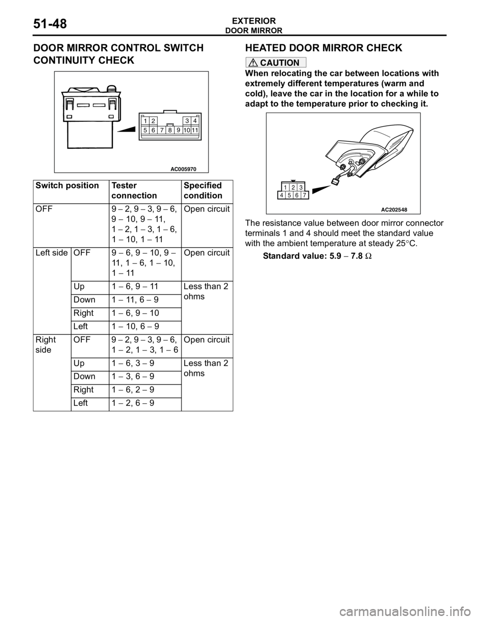
DOOR MIRROR CONTROL SWITCH
CONTINUITY CHECKHEATED DOOR MIRROR CHECK
CAUTION
When relocating the car between locations with
extremely different temperatures (warm and
cold), leave the car in the location for a while to
adapt to the temperature prior to checking it.
The resistance value between door mirror connector
terminals 1 and 4 should meet the standard value
with the ambient temperature at steady 25°C.
Standard value: 5.9 − 7.8 Ω Switch position Tester
connectionSpecified
condition
OFF 9 − 2, 9 − 3, 9 − 6,
9 − 10, 9 − 11 ,
1 − 2, 1 − 3, 1 − 6,
1 − 10, 1 − 11Open circuit
Left side OFF 9 − 6, 9 − 10, 9 −
11 , 1 − 6, 1 − 10,
1 − 11Open circuit
Up 1 − 6, 9 − 11 Less than 2
ohms
Down 1 − 11 , 6 − 9
Right 1 − 6, 9 − 10
Left 1 − 10, 6 − 9
Right
sideOFF 9 − 2, 9 − 3, 9 − 6,
1 − 2, 1 − 3, 1 − 6Open circuit
Up 1 − 6, 3 − 9 Less than 2
ohms
Down 1 − 3, 6 − 9
Right 1 − 6, 2 − 9
Left 1 − 2, 6 − 9
AC005970
2
14 3
5109
8
7 611
AC202548
1
456723
Page 390 of 788
54A-2
COMBINATION METER
ASSEMBLY . . . . . . . . . . . . . . . .
54A-29
SERVICE SPECIFICATIONS. . . . .
54A-29
SEALANT. . . . . . . . . . . . . . . . . . . .54A-29
SPECIAL TOOLS. . . . . . . . . . . . . .54A-29
TROUBLESHOOTING . . . . . . . . . .54A-31
SYMPTOM CHART . . . . . . . . . . . . . . . . 54A-31
SYMPTOM PROCEDURES . . . . . .54A-32
ON-VEHICLE SERVICE. . . . . . . . .54A-60
SPEEDOMETER CHECK . . . . . . . . . . . 54A-60
TACHOMETER CHECK . . . . . . . . . . . . 54A-60
FUEL TANK GAUGE UNIT CHECK . . . 54A-61
ENGINE COOLANT TEMPERATURE GAUGE
UNIT CHECK . . . . . . . . . . . . . . . . . . . . . 54A-61
COMBINATION METER ASSEMBLY54A-63
REMOVAL AND INSTALLATION . . . . . 54A-63
INSPECTION . . . . . . . . . . . . . . . . . . . . . 54A-64
DISASSEMBLY AND REASSEMBLY . . 54A-65
HEADLAMP . . . . . . . . . . . . . . . .54A-66
SERVICE SPECIFICATIONS. . . . .
54A-66
TROUBLESHOOTING . . . . . . . . . .54A-66
ON-VEHICLE SERVICE. . . . . . . . .54A-66
HEADLAMP AIMING . . . . . . . . . . . . . . . 54A-66
LUMINOUS INTENSITY
MEASUREMENT . . . . . . . . . . . . . . . . . . 54A-67
BULB REPLACEMENT . . . . . . . . . . . . . 54A-68
HEADLAMP . . . . . . . . . . . . . . . . . .54A-69
REMOVAL AND INSTALLATION . . . . . 54A-69
HEADLAMP LEVELING SWITCH .54A-70
REMOVAL AND INSTALLATION . . . . . 54A-70
INSPECTION . . . . . . . . . . . . . . . . . . . . . 54A-70
FOG LAMP . . . . . . . . . . . . . . . . 54A-71
SERVICE SPECIFICATION . . . . . .
54A-71
SPECIAL TOOL . . . . . . . . . . . . . . .54A-71
TROUBLESHOOTING . . . . . . . . . .54A-71
ON-VEHICLE SERVICE . . . . . . . . .54A-71
FRONT FOG LAMP AIMING CHECK . . 54A-71
FOG LAMP . . . . . . . . . . . . . . . . . . .54A-73
REMOVAL AND INSTALLATION . . . . . . 54A-73
FOG LAMP SWITCH . . . . . . . . . . .54A-74
REMOVAL AND INSTALLATION . . . . . . 54A-74
INSPECTION . . . . . . . . . . . . . . . . . . . . . 54A-74
REAR FOG LAMP . . . . . . . . . . 54A-75
TROUBLESHOOTING . . . . . . . . . .
54A-75
SPECIAL TOOL . . . . . . . . . . . . . . .54A-75
REAR FOG LAMP . . . . . . . . . . . . .54A-76
REMOVAL AND INSTALLATION . . . . . . 54A-76
REAR FOG LAMP SWITCH . . . . . .54A-76
REMOVAL AND INSTALATION . . . . . . . 54A-76
INSPECTION . . . . . . . . . . . . . . . . . . . . . 54A-76
SIDE TURN-SIGNAL LAMP. . . 54A-77
SPECIAL TOOL . . . . . . . . . . . . . . .
54A-77
SIDE TURN-SIGNAL LAMP . . . . . .54A-77
REMOVAL AND INSTALLATION . . . . . . 54A-77
ROOM LAMP . . . . . . . . . . . . . . 54A-78
TROUBLESHOOTING . . . . . . . . . . . . . . 54A-78
Continued on next page
Page 394 of 788
IGNITION SWITCH
CHASSIS ELECTRICAL54A-6
IGNITION SWITCH
GENERAL INFORMATIONM1543009901274
IGNITION KEY REMINDER BUZZER
The ignition key reminder buzzer will sound under
the following condition, and warn the driver to
remove the ignition key.
•The driver's door is opened when the ignition
switch is at "LOCK" (OFF) or "ACC" position
without removing the ignition key.
However, the lamp reminder buzzer will take
precedence over this function.
DOOR LOCK PREVENTION FUNCTION
If the key is left in the ignition switch while the driver’s
door opened or the assistant door opened, all door
are automatically unlock to prevent locking the
ignition key in the vehicle after door is locked.
IMMOBILIZER SYSTEM
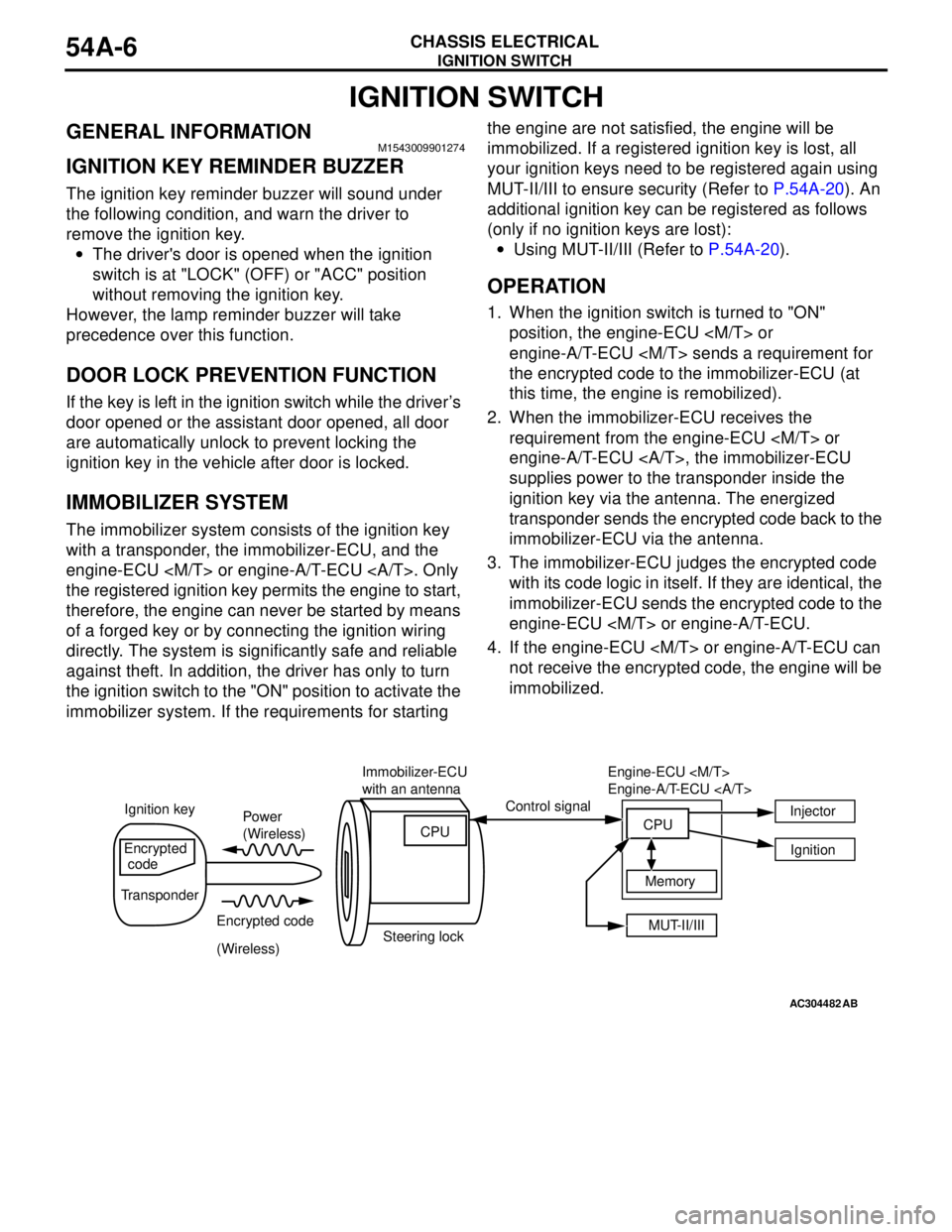
The immobilizer system consists of the ignition key
with a transponder, the immobilizer-ECU, and the
engine-ECU
the registered ignition key permits the engine to start,
therefore, the engine can never be started by means
of a forged key or by connecting the ignition wiring
directly. The system is significantly safe and reliable
against theft. In addition, the driver has only to turn
the ignition switch to the "ON" position to activate the
immobilizer system. If the requirements for starting the engine are not satisfied, the engine will be
immobilized. If a registered ignition key is lost, all
your ignition keys need to be registered again using
MUT-II/III to ensure security (Refer to P.54A-20). An
additional ignition key can be registered as follows
(only if no ignition keys are lost):
•Using MUT-II/III (Refer to P.54A-20).
OPERATION
1. When the ignition switch is turned to "ON"
position, the engine-ECU
engine-A/T-ECU
the encrypted code to the immobilizer-ECU (at
this time, the engine is remobilized).
2. When the immobilizer-ECU receives the
requirement from the engine-ECU
engine-A/T-ECU , the immobilizer-ECU
supplies power to the transponder inside the
ignition key via the antenna. The energized
transponder sends the encrypted code back to the
immobilizer-ECU via the antenna.
3. The immobilizer-ECU judges the encrypted code
with its code logic in itself. If they are identical, the
immobilizer-ECU sends the encrypted code to the
engine-ECU
4. If the engine-ECU
not receive the encrypted code, the engine will be
immobilized.
AC304482AB
Power
(Wireless)
Encrypted code
(Wireless) Ignition keyControl signal
Encrypted
code
TransponderImmobilizer-ECU
with an antenna
Steering lockCPU
MUT-II/III Memory Engine-ECU
Engine-A/T-ECU
CPUInjector
Ignition
Page 399 of 788
IGNITION SWITCH
CHASSIS ELECTRICAL54A-11
DIAGNOSIS PROCEDURE
STEP 1. Check for presence of other key near the
key in the ignition.
Q: Is there any other key near the key in the ignition?
YES :
Move the other key well away from key
being used. Retest the system.
NO : Go to Step 2.
STEP 2. Check that the engine start using the
spare ignition key which encrypted code has
been registered.
Q: Does the engine start using the spare ignition key
for which the encrypted code has been registered?
YES :
Replace the ignition key that does not work.
Then register the password (secret code)
and encrypted code P.54A-20. Retest the
system.
NO : Go to Step 3.
STEP 3. Check whether the diagnosis code is
reset.
Q: Which diagnosis code is set, code No.11 or 12 the
encrypted code has been registered?
Code No.12 is set :
Refer toP.54A-11.
Code No.11 is set : Go to Step 4.
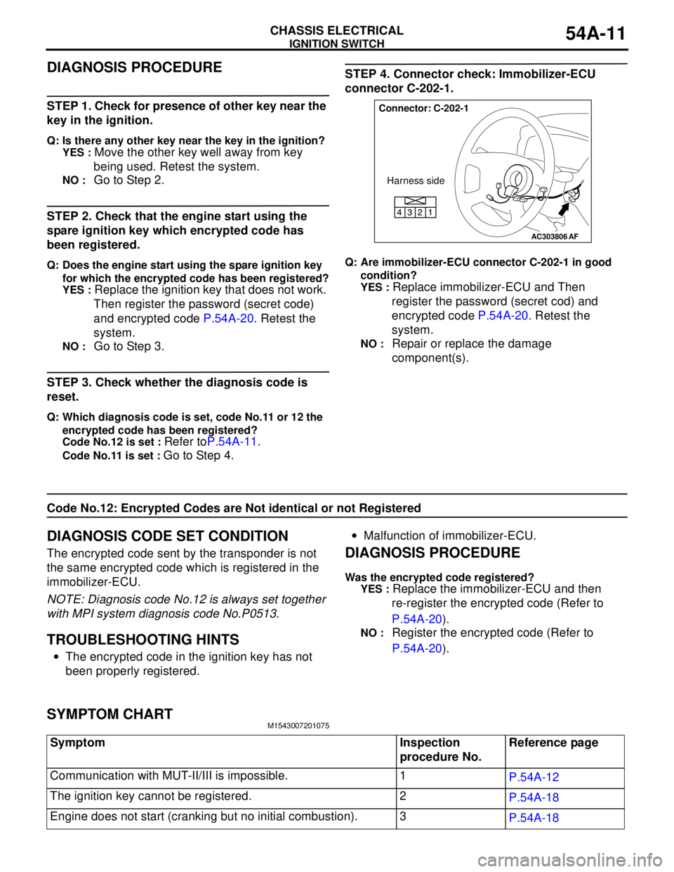
STEP 4. Connector check: Immobilizer-ECU
connector C-202-1.
Q: Are immobilizer-ECU connector C-202-1 in good
condition?
YES :
Replace immobilizer-ECU and Then
register the password (secret cod) and
encrypted code P.54A-20. Retest the
system.
NO : Repair or replace the damage
component(s).
Code No.12: Encrypted Codes are Not identical or not Registered
DIAGNOSIS CODE SET CONDITION
The encrypted code sent by the transponder is not
the same encrypted code which is registered in the
immobilizer-ECU.
NOTE: Diagnosis code No.12 is always set together
with MPI system diagnosis code No.P0513.
TROUBLESHOOTING HINTS
•The encrypted code in the ignition key has not
been properly registered.•Malfunction of immobilizer-ECU.
DIAGNOSIS PROCEDURE
Was the encrypted code registered?
YES :
Replace the immobilizer-ECU and then
re-register the encrypted code (Refer to
P.54A-20).
NO : Register the encrypted code (Refer to
P.54A-20).
SYMPTOM CHARTM1543007201075
AC303806
Connector: C-202-1
Harness side
AF
Symptom Inspection
procedure No.Reference page
Communication with MUT-II/III is impossible. 1
P.54A-12
The ignition key cannot be registered. 2
P.54A-18
Engine does not start (cranking but no initial combustion). 3
P.54A-18
Page 401 of 788
IGNITION SWITCH
CHASSIS ELECTRICAL54A-13
TROUBLESHOOTING HINTS
•Malfunction of the immobilizer-ECU.
•Malfunction of the engine-ECU
engine-A/T-ECU .
•The wiring harness or connectors may have
loose, corroded, or damaged terminals, or
terminals pushed back in the connector.
DIAGNOSIS PROCEDURE
STEP 1. Check if MUT-II/III can communicate with
the MPI system and if an MPI system diagnosis
code other than P0513 is set.
Q: Can MUT-II/III communicate with the MPI system?
Is an MPI system diagnosis code other than P0513
set?
YES :
Go to Step 2.
NO : Refer to GROUP 13A, MPI Diagnosis
P.13A-15, GROUP 13B, MPI Diagnosis
P.13B-15.
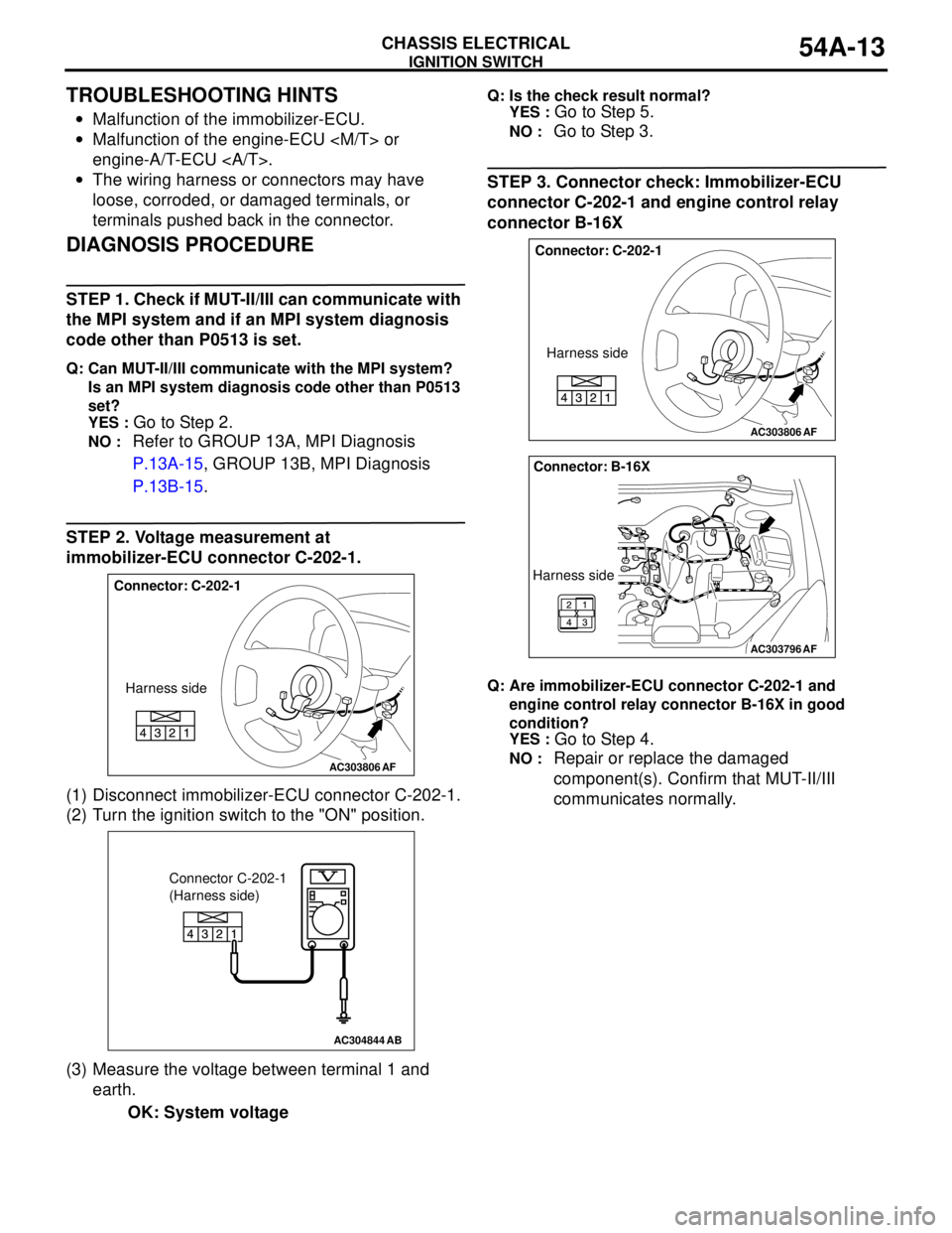
STEP 2. Voltage measurement at
immobilizer-ECU connector C-202-1.
(1) Disconnect immobilizer-ECU connector C-202-1.
(2) Turn the ignition switch to the "ON" position.
(3) Measure the voltage between terminal 1 and
earth.
OK: System voltage
Q: Is the check result normal?
YES :
Go to Step 5.
NO : Go to Step 3.
STEP 3. Connector check: Immobilizer-ECU
connector C-202-1 and engine control relay
connector B-16X
Q: Are immobilizer-ECU connector C-202-1 and
engine control relay connector B-16X in good
condition?
YES :
Go to Step 4.
NO : Repair or replace the damaged
component(s). Confirm that MUT-II/III
communicates normally.AC303806
Connector: C-202-1
Harness side
AF
AC304844AB
Connector C-202-1
(Harness side)
AC303806
Connector: C-202-1
Harness side
AF
AC303796
Connector: B-16X
Harness side
AF