Side MITSUBISHI LANCER 2005 Workshop Manual
[x] Cancel search | Manufacturer: MITSUBISHI, Model Year: 2005, Model line: LANCER, Model: MITSUBISHI LANCER 2005Pages: 788, PDF Size: 45.98 MB
Page 402 of 788
IGNITION SWITCH
CHASSIS ELECTRICAL54A-14
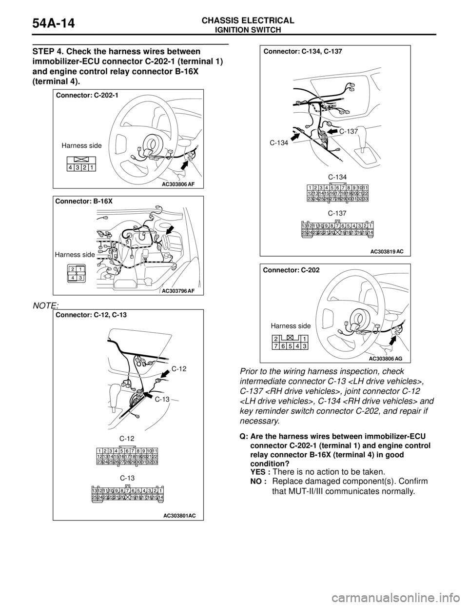
STEP 4. Check the harness wires between
immobilizer-ECU connector C-202-1 (terminal 1)
and engine control relay connector B-16X
(terminal 4).
NOTE:
Prior to the wiring harness inspection, check
intermediate connector C-13
C-137
key reminder switch connector C-202, and repair if
necessary.
Q: Are the harness wires between immobilizer-ECU
connector C-202-1 (terminal 1) and engine control
relay connector B-16X (terminal 4) in good
condition?
YES :
There is no action to be taken.
NO : Replace damaged component(s). Confirm
that MUT-II/III communicates normally.
AC303806
Connector: C-202-1
Harness side
AF
AC303796
Connector: B-16X
Harness side
AF
AC303801
Connector: C-12, C-13
C-12
C-13
C-12
C-13
AC
AC303819
Connector: C-134, C-137
C-134
C-137
C-134
C-137
AC
AC303806
Connector: C-202
Harness side
AG
Page 403 of 788
IGNITION SWITCH
CHASSIS ELECTRICAL54A-15
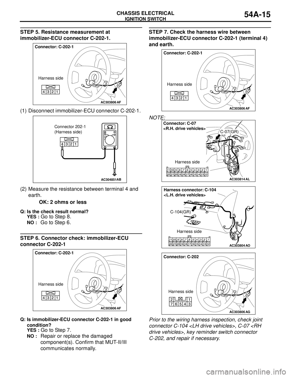
STEP 5. Resistance measurement at
immobilizer-ECU connector C-202-1.
(1) Disconnect immobilizer-ECU connector C-202-1.
(2) Measure the resistance between terminal 4 and
earth.
OK: 2 ohms or less
Q: Is the check result normal?
YES :
Go to Step 8.
NO : Go to Step 6.
STEP 6. Connector check: immobilizer-ECU
connector C-202-1
Q: Is immobilizer-ECU connector C-202-1 in good
condition?
YES :
Go to Step 7.
NO : Repair or replace the damaged
component(s). Confirm that MUT-II/III
communicates normally.
STEP 7. Check the harness wire between
immobilizer-ECU connector C-202-1 (terminal 4)
and earth.
NOTE:
Prior to the wiring harness inspection, check joint
connector C-104
C-202, and repair if necessary.
AC303806
Connector: C-202-1
Harness side
AF
AC304851AB
Connector 202-1
(Harness side)
AC303806
Connector: C-202-1
Harness side
AF
AC303806
Connector: C-202-1
Harness side
AF
AC303814
Connector: C-07
C-07(GR)
Harness side
AL
AC303804AO
Harness connector: C-104
C-104(GR)
Harness side
AC303806
Connector: C-202
Harness side
AG
Page 404 of 788
IGNITION SWITCH
CHASSIS ELECTRICAL54A-16
Q: Is the harness wire between immobilizer-ECU
connector C-202-1 (terminal 4) and earth in good
condition?
YES :
There is no action to be taken.
NO : Repair or replace the damaged
component(s). Confirm that MUT-II/III
communicates normally.
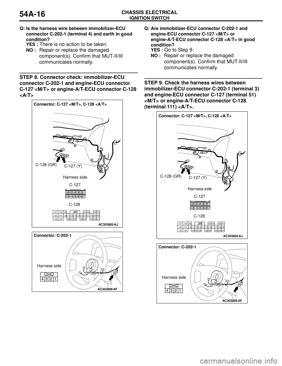
STEP 8. Connector check: immobilizer-ECU
connector C-202-1 and engine-ECU connector
C-127
Q: Are immobilizer-ECU connector C-202-1 and
engine-ECU connector C-127
engine-A/T-ECU connector C-128 in good
condition?
YES :
Go to Step 9.
NO : Repair or replace the damaged
component(s). Confirm that MUT-II/III
communicates normally.
STEP 9. Check the harness wires between
immobilizer-ECU connector C-202-1 (terminal 3)
and engine-ECU connector C-127 (terminal 51)
(terminal 111) .
AC303805
Connector: C-127
C-128 (GR)
C-127 (Y)
C-127
C-128
585261556256605459535751
101 102
103 104 105 106 107
120 119 118 117 116 115 114 113 112 111 110 109 108
121 122 123 124 125 126 127 128 129 130
Harness side
AJ
AC303806
Connector: C-202-1
Harness side
AF
AC303805
Connector: C-127
C-128 (GR)
C-127 (Y)
C-127
C-128
585261556256605459535751
101 102
103 104 105 106 107
120 119 118 117 116 115 114 113 112 111 110 109 108
121 122 123 124 125 126 127 128 129 130
Harness side
AJ
AC303806
Connector: C-202-1
Harness side
AF
Page 405 of 788
IGNITION SWITCH
CHASSIS ELECTRICAL54A-17
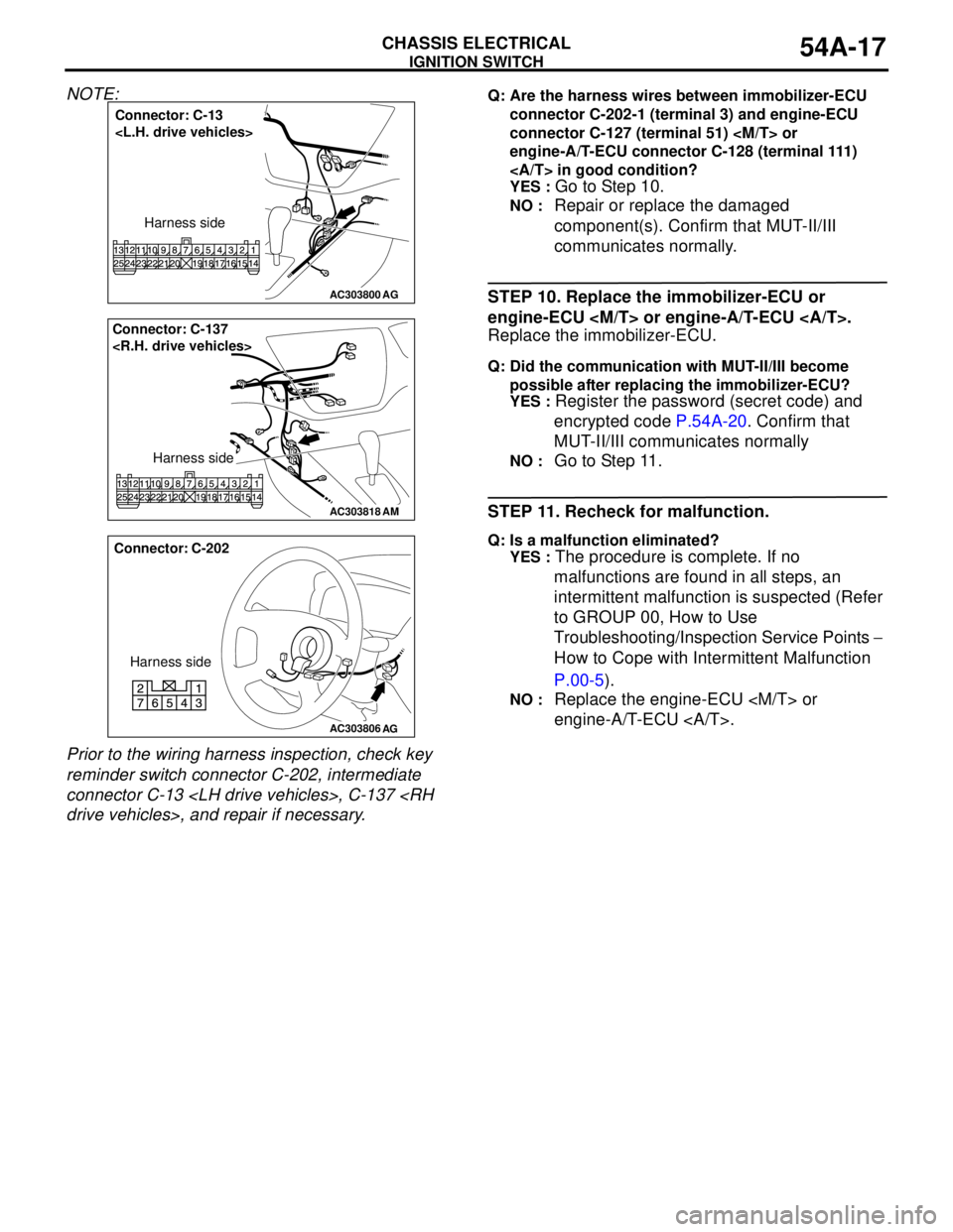
NOTE:
Prior to the wiring harness inspection, check key
reminder switch connector C-202, intermediate
connector C-13
connector C-202-1 (terminal 3) and engine-ECU
connector C-127 (terminal 51)
engine-A/T-ECU connector C-128 (terminal 111)
in good condition?
YES :
Go to Step 10.
NO : Repair or replace the damaged
component(s). Confirm that MUT-II/III
communicates normally.
STEP 10. Replace the immobilizer-ECU or
engine-ECU
Replace the immobilizer-ECU.
Q: Did the communication with MUT-II/III become
possible after replacing the immobilizer-ECU?
YES :
Register the password (secret code) and
encrypted code P.54A-20. Confirm that
MUT-II/III communicates normally
NO : Go to Step 11.
STEP 11. Recheck for malfunction.
Q: Is a malfunction eliminated?
YES :
The procedure is complete. If no
malfunctions are found in all steps, an
intermittent malfunction is suspected (Refer
to GROUP 00, How to Use
Troubleshooting/Inspection Service Points −
How to Cope with Intermittent Malfunction
P.00-5).
NO : Replace the engine-ECU
engine-A/T-ECU .
AC303800
Connector: C-13
Harness side
AG
AC303818
AM
Connector: C-137
Harness side
AC303806
Connector: C-202
Harness side
AG
Page 420 of 788
COMBINATION METER ASSEMBLY
CHASSIS ELECTRICAL54A-32
SYMPTOM PROCEDURES
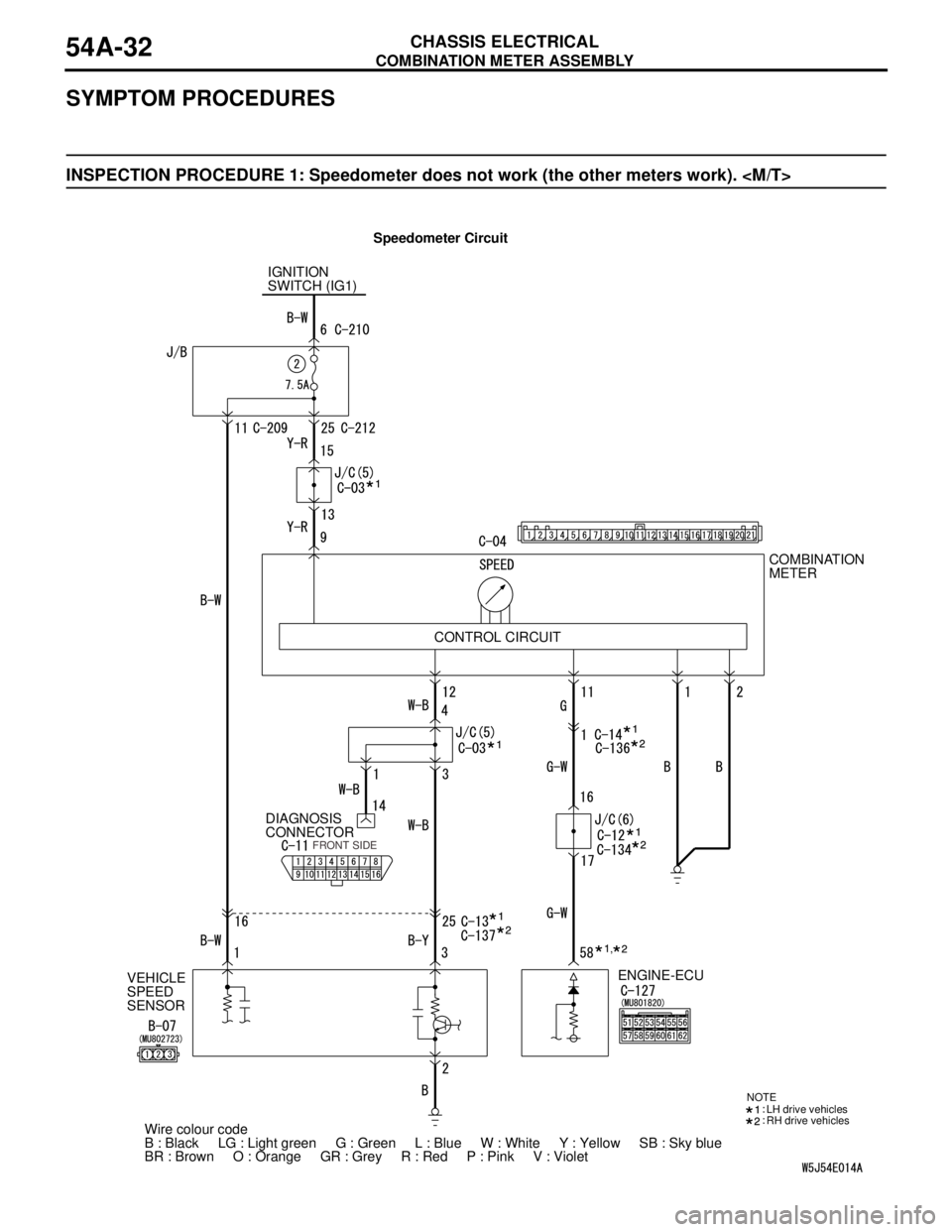
INSPECTION PROCEDURE 1: Speedometer does not work (the other meters work).
Speedometer Circuit
IGNITION
SWITCH (IG1)
VEHICLE
SPEED
SENSORDIAGNOSIS
CONNECTORCOMBINATION
METER
ENGINE-ECU
Wire colour code
B : Black LG : Light green G : Green L : Blue W : White Y : Yellow SB : Sky blue
BR : Brown O : Orange GR : Grey R : Red P : Pink V : Violet CONTROL CIRCUIT
FRONT SIDE
NOTE
LH drive vehicles
RH drive vehicles
,
Page 422 of 788
COMBINATION METER ASSEMBLY
CHASSIS ELECTRICAL54A-34
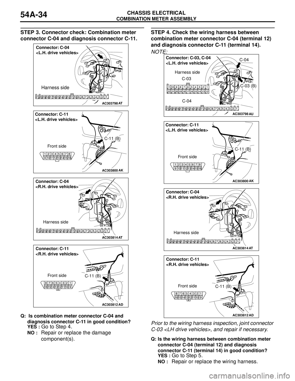
STEP 3. Connector check: Combination meter
connector C-04 and diagnosis connector C-11.
Q: Is combination meter connector C-04 and
diagnosis connector C-11 in good condition?
YES :
Go to Step 4.
NO : Repair or replace the damage
component(s).
STEP 4. Check the wiring harness between
combination meter connector C-04 (terminal 12)
and diagnosis connector C-11 (terminal 14).
NOTE:
Prior to the wiring harness inspection, joint connector
C-03
Q: Is the wiring harness between combination meter
connector C-04 (terminal 12) and diagnosis
connector C-11 (terminal 14) in good condition?
YES :
Go to Step 5.
NO : Repair or replace the wiring harness.
AC303798
Connector: C-04
Harness side
AT
AC303800
C-11 (B) Connector: C-11
Front side
AK
AC303814
Connector: C-04
Harness side
AT
AC303812
AD
Connector: C-11
Front side
C-11 (B)
AC303798AU
Connector: C-03, C-04
C-03 (B)
C-04 C-03 Harness side
AC303800
C-11 (B) Connector: C-11
Front side
AK
AC303814
Connector: C-04
Harness side
AT
AC303812
AD
Connector: C-11
Front side
C-11 (B)
Page 423 of 788
COMBINATION METER ASSEMBLY
CHASSIS ELECTRICAL54A-35
STEP 5. Retest the system
Q: Is the speedometer normal?
YES : .
The procedure is complete. (If no
malfunctions are found in all steps, an
intermittent malfunction is suspected. Refer
to GROUP 00, How to Use
Troubleshooting/Inspection Service
Points-How to Cope with Intermittent
Malfunction P.00-5).
NO : . Replace the combination meter assembly.
STEP 6. Check whether the diagnosis code is
reset.
Q: Is the MPI-related diagnosis code set?
YES :
Refer to GROUP 13A − Troubleshooting
P.13A-15, GROUP 13B − Troubleshooting
P.13B-15.
NO : . Go to Step 7.
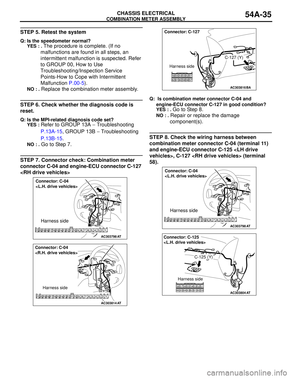
STEP 7. Connector check: Combination meter
connector C-04 and engine-ECU connector C-127
Q: Is combination meter connector C-04 and
engine-ECU connector C-127 in good condition?
YES : .
Go to Step 8.
NO : . Repair or replace the damage
component(s).
STEP 8. Check the wiring harness between
combination meter connector C-04 (terminal 11)
and engine-ECU connector C-125
58).
AC303798
Connector: C-04
Harness side
AT
AC303814
Connector: C-04
Harness side
AT
AC303816BA
Connector: C-127
C-127 (Y)
Harness side
AC303798
Connector: C-04
Harness side
AT
AC303804
Connector: C-125
C-125 (Y)
Harness side
51 52 53 54 55 56 57 58
66 65 64 63 62 61 60 59
AT
Page 424 of 788
COMBINATION METER ASSEMBLY
CHASSIS ELECTRICAL54A-36
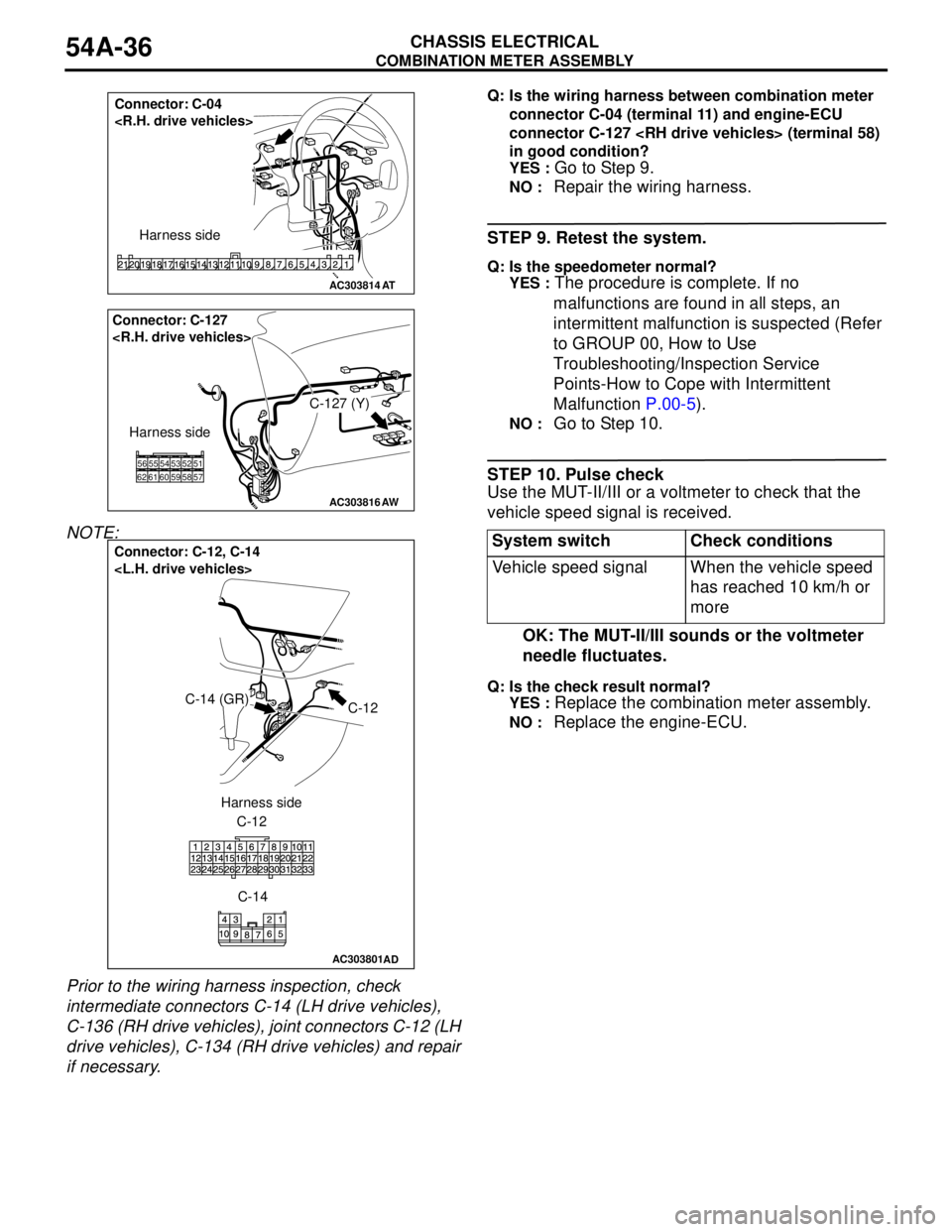
NOTE:
Prior to the wiring harness inspection, check
intermediate connectors C-14 (LH drive vehicles),
C-136 (RH drive vehicles), joint connectors C-12 (LH
drive vehicles), C-134 (RH drive vehicles) and repair
if necessary.
Q: Is the wiring harness between combination meter
connector C-04 (terminal 11) and engine-ECU
connector C-127
in good condition?
YES :
Go to Step 9.
NO : Repair the wiring harness.
STEP 9. Retest the system.
Q: Is the speedometer normal?
YES :
The procedure is complete. If no
malfunctions are found in all steps, an
intermittent malfunction is suspected (Refer
to GROUP 00, How to Use
Troubleshooting/Inspection Service
Points-How to Cope with Intermittent
Malfunction P.00-5).
NO : Go to Step 10.
STEP 10. Pulse check
Use the MUT-II/III or a voltmeter to check that the
vehicle speed signal is received.
OK: The MUT-II/III sounds or the voltmeter
needle fluctuates.
Q: Is the check result normal?
YES :
Replace the combination meter assembly.
NO : Replace the engine-ECU.
AC303814
Connector: C-04
Harness side
AT
AC303816AW
Connector: C-127
C-127 (Y)
Harness side
585261556256605459535751
AC303801
Connector: C-12, C-14
C-12C-14 (GR)
C-12
C-14 Harness side
AD
System switch Check conditions
Vehicle speed signal When the vehicle speed
has reached 10 km/h or
more
Page 425 of 788
COMBINATION METER ASSEMBLY
CHASSIS ELECTRICAL54A-37
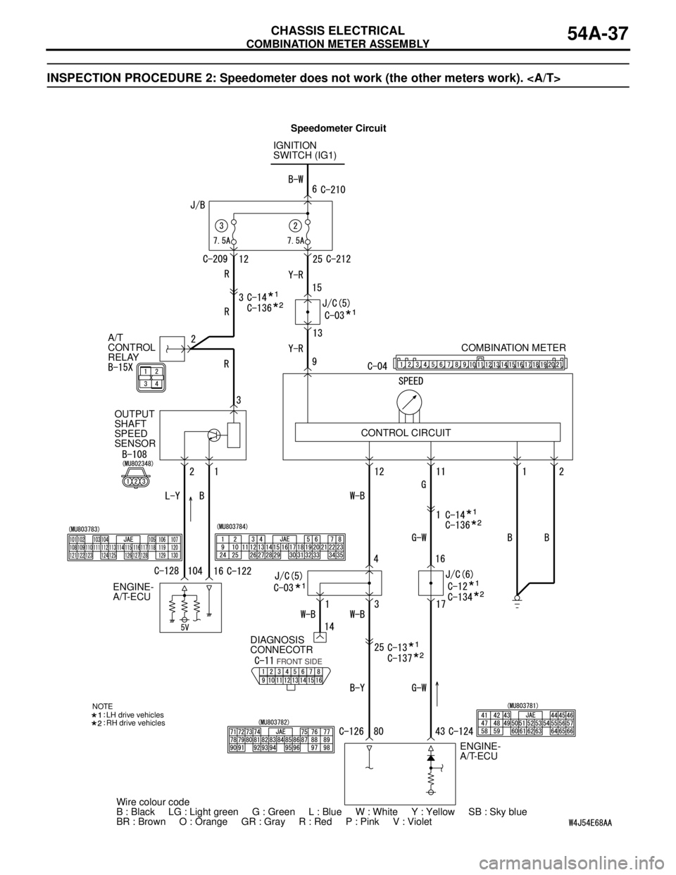
INSPECTION PROCEDURE 2: Speedometer does not work (the other meters work).
IGNITION
SWITCH (IG1)
A/T
CONTROL
RELAY
OUTPUT
SHAFT
SPEED
SENSOR
DIAGNOSIS
CONNECOTR
ENGINE-
A/T-ECUCOMBINATION METER
ENGINE-
A/T-ECU
Wire colour code
B : Black LG : Light green G : Green L : Blue W : White Y : Yellow SB : Sky blue
BR : Brown O : Orange GR : Gray R : Red P : Pink V : Violet
FRONT SIDE
NOTE
LH drive vehicles
RH drive vehicles
CONTROL CIRCUIT
Speedometer Circuit
Page 427 of 788
COMBINATION METER ASSEMBLY
CHASSIS ELECTRICAL54A-39
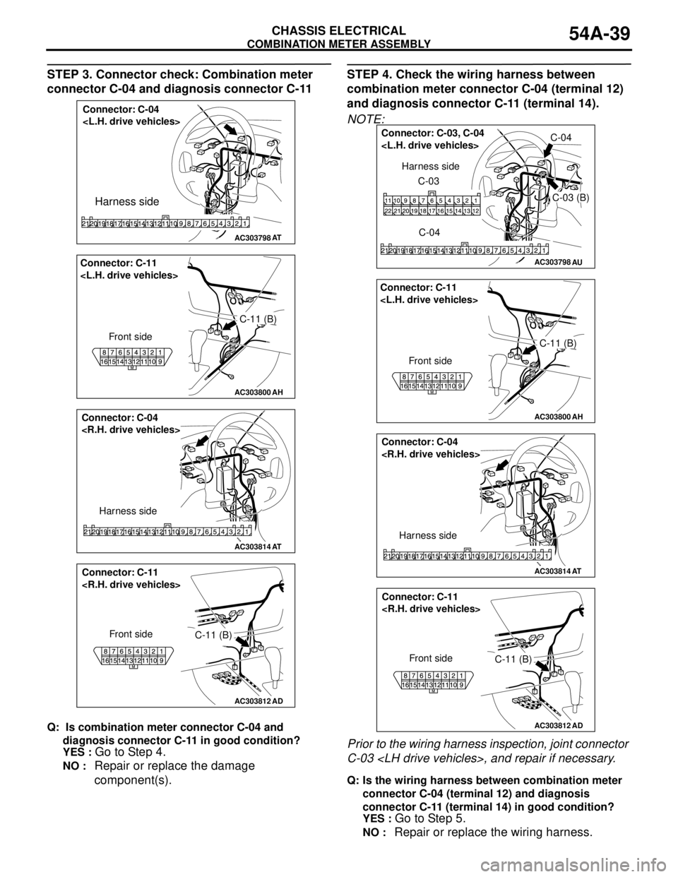
STEP 3. Connector check: Combination meter
connector C-04 and diagnosis connector C-11
Q: Is combination meter connector C-04 and
diagnosis connector C-11 in good condition?
YES :
Go to Step 4.
NO : Repair or replace the damage
component(s).
STEP 4. Check the wiring harness between
combination meter connector C-04 (terminal 12)
and diagnosis connector C-11 (terminal 14).
NOTE:
Prior to the wiring harness inspection, joint connector
C-03
Q: Is the wiring harness between combination meter
connector C-04 (terminal 12) and diagnosis
connector C-11 (terminal 14) in good condition?
YES :
Go to Step 5.
NO : Repair or replace the wiring harness.
AC303798
Connector: C-04
Harness side
AT
AC303800
C-11 (B) Connector: C-11
Front side
AH
AC303814
Connector: C-04
Harness side
AT
AC303812
AD
Connector: C-11
Front side
C-11 (B)
AC303798AU
Connector: C-03, C-04
C-03 (B)
C-04 C-03 Harness side
AC303800
C-11 (B) Connector: C-11
Front side
AH
AC303814
Connector: C-04
Harness side
AT
AC303812
AD
Connector: C-11
Front side
C-11 (B)