MITSUBISHI LANCER 2005 Workshop Manual
Manufacturer: MITSUBISHI, Model Year: 2005, Model line: LANCER, Model: MITSUBISHI LANCER 2005Pages: 788, PDF Size: 45.98 MB
Page 251 of 788
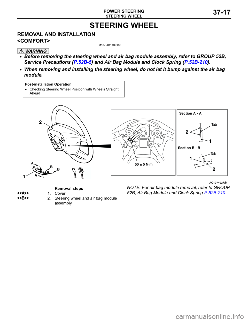
STEERING WHEEL
POWER STEERING37-17
STEERING WHEEL
REMOVAL AND INSTALLATION
M1372011400183
WARNING
•Before removing the steering wheel and air bag module assembly, refer to GROUP 52B,
Service Precautions (P.52B-5) and Air Bag Module and Clock Spring (P.52B-210).
•When removing and installing the steering wheel, do not let it bump against the air bag
module.
NOTE: For air bag module removal, refer to GROUP
52B, Air Bag Module and Clock Spring P.52B-210.
Post-installation Operation
•Checking Steering Wheel Position with Wheels Straight
Ahead
AC107402AB
50 ± 5 N·m
1 2
2
1
12
A
AB
BTa b
Ta b Section A - A
Section B - B
Removal steps
<>1. Cover
<>2. Steering wheel and air bag module
assembly
Page 252 of 788
Page 253 of 788
STEERING WHEEL
POWER STEERING37-19
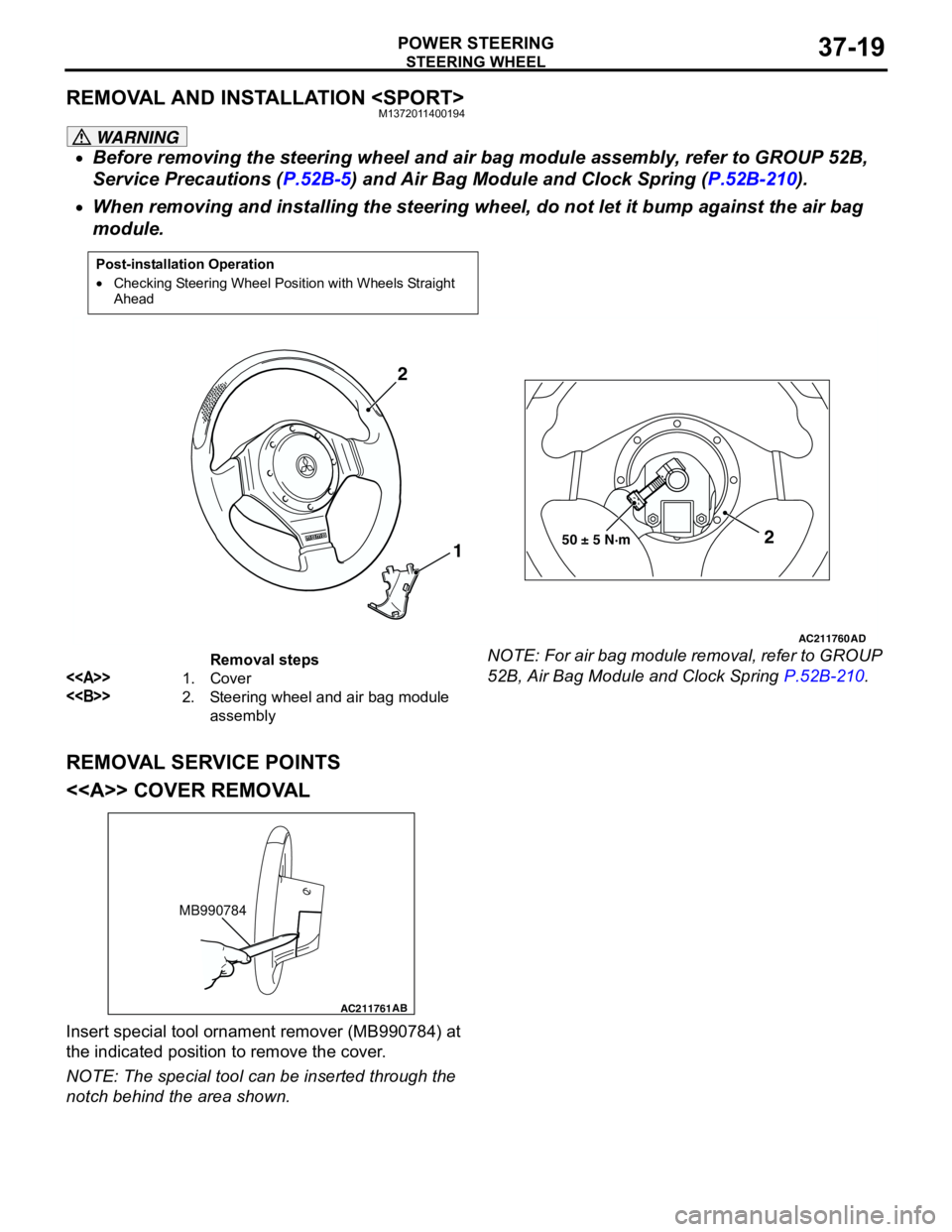
REMOVAL AND INSTALLATION
WARNING
•Before removing the steering wheel and air bag module assembly, refer to GROUP 52B,
Service Precautions (P.52B-5) and Air Bag Module and Clock Spring (P.52B-210).
•When removing and installing the steering wheel, do not let it bump against the air bag
module.
NOTE: For air bag module removal, refer to GROUP
52B, Air Bag Module and Clock Spring P.52B-210.
REMOVAL SERVICE POINTS
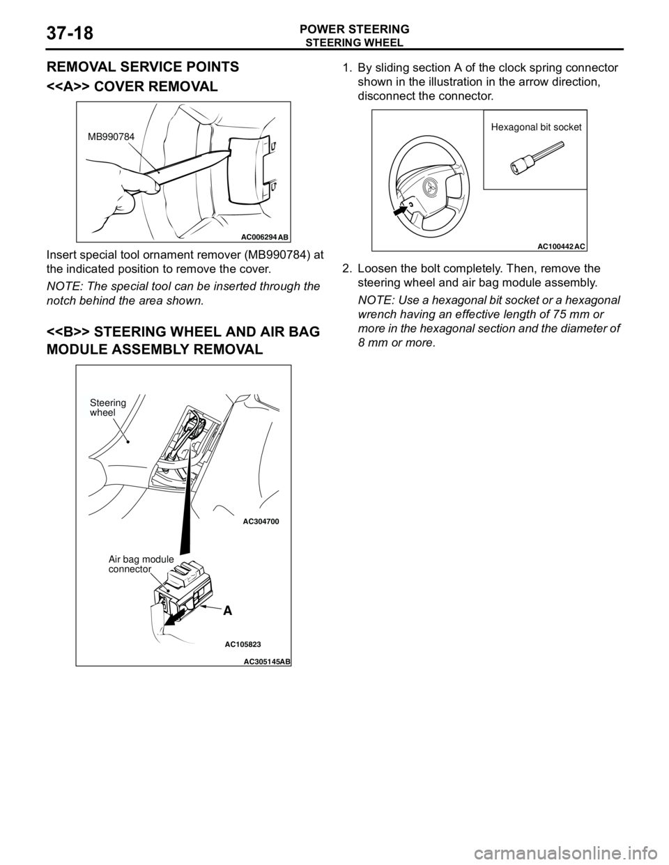
<> COVER REMOVAL
Insert special tool ornament remover (MB990784) at
the indicated position to remove the cover.
NOTE: The special tool can be inserted through the
notch behind the area shown.
Post-installation Operation
•Checking Steering Wheel Position with Wheels Straight
Ahead
AC211760
AD
50 ± 5 N·m2
1 2
Removal steps
<>1. Cover
<>2. Steering wheel and air bag module
assembly
AC211761AB
MB990784
Page 254 of 788
STEERING WHEEL
POWER STEERING37-20
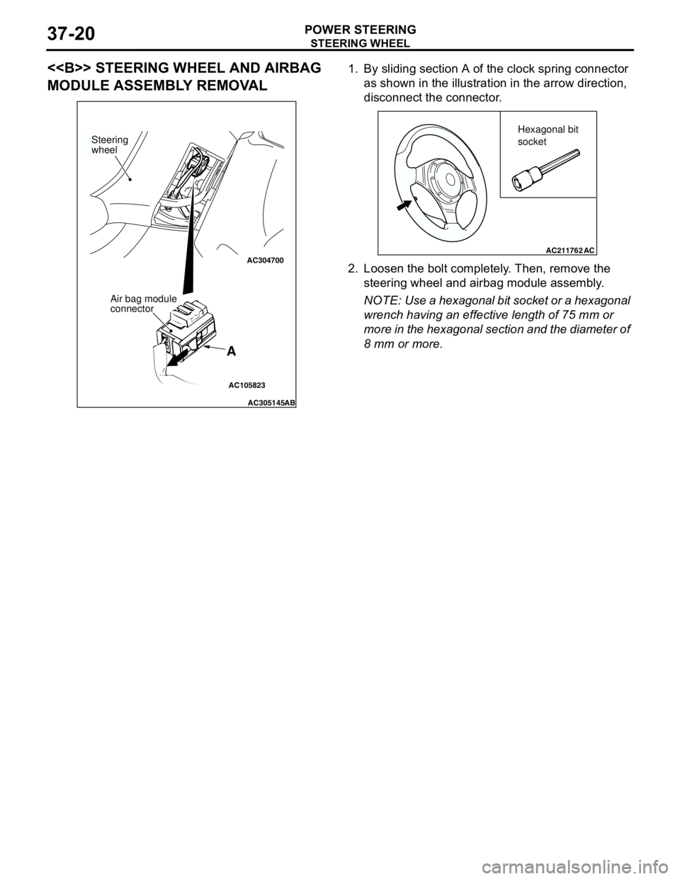
<> STEERING WHEEL AND AIRBAG
MODULE ASSEMBLY REMOVAL1. By sliding section A of the clock spring connector
as shown in the illustration in the arrow direction,
disconnect the connector.
2. Loosen the bolt completely. Then, remove the
steering wheel and airbag module assembly.
NOTE: Use a hexagonal bit socket or a hexagonal
wrench having an effective length of 75 mm or
more in the hexagonal section and the diameter of
8 mm or more.
AC105823
AC304700
AC305145AB
A
Steering
wheel
Air bag module
connector
AC211762AC
Hexagonal bit
socket
Page 255 of 788
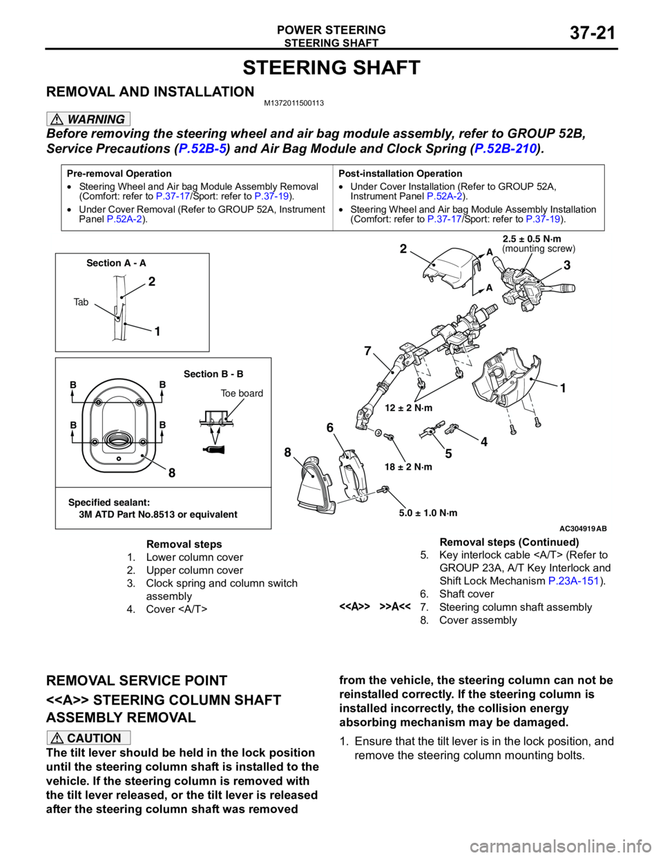
STEERING SHAFT
POWER STEERING37-21
STEERING SHAFT
REMOVAL AND INSTALLATIONM1372011500113
WARNING
Before removing the steering wheel and air bag module assembly, refer to GROUP 52B,
Service Precautions (P.52B-5) and Air Bag Module and Clock Spring (P.52B-210).
REMOVAL SERVICE POINT
<> STEERING COLUMN SHAFT
ASSEMBLY REMOVAL
CAUTION
The tilt lever should be held in the lock position
until the steering column shaft is installed to the
vehicle. If the steering column is removed with
the tilt lever released, or the tilt lever is released
after the steering column shaft was removed from the vehicle, the steering column can not be
reinstalled correctly. If the steering column is
installed incorrectly, the collision energy
absorbing mechanism may be damaged.
1. Ensure that the tilt lever is in the lock position, and
remove the steering column mounting bolts.
Pre-removal Operation
•Steering Wheel and Air bag Module Assembly Removal
(Comfort: refer to P.37-17/Sport: refer to P.37-19).
•Under Cover Removal (Refer to GROUP 52A, Instrument
Panel P.52A-2).Post-installation Operation
•Under Cover Installation (Refer to GROUP 52A,
Instrument Panel P.52A-2).
•Steering Wheel and Air bag Module Assembly Installation
(Comfort: refer to P.37-17/Sport: refer to P.37-19).
AC304919AB
12 ± 2 N·m
18 ± 2 N·m
5.0 ± 1.0 N·m
1 2
73 2
1
8
86
A
A
Ta bSection A - A
Section B - B
BB
Toe board
Specified sealant:
3M ATD Part No.8513 or equivalent
BB
4
5
(mounting screw)2.5 ± 0.5 N·m
Removal steps
1. Lower column cover
2. Upper column cover
3. Clock spring and column switch
assembly
4. Cover 5. Key interlock cable (Refer to
GROUP 23A, A/T Key Interlock and
Shift Lock Mechanism P.23A-151).
6. Shaft cover
<> >>A<<7. Steering column shaft assembly
8. Cover assemblyRemoval steps (Continued)
Page 256 of 788
STEERING SHAFT
POWER STEERING37-22
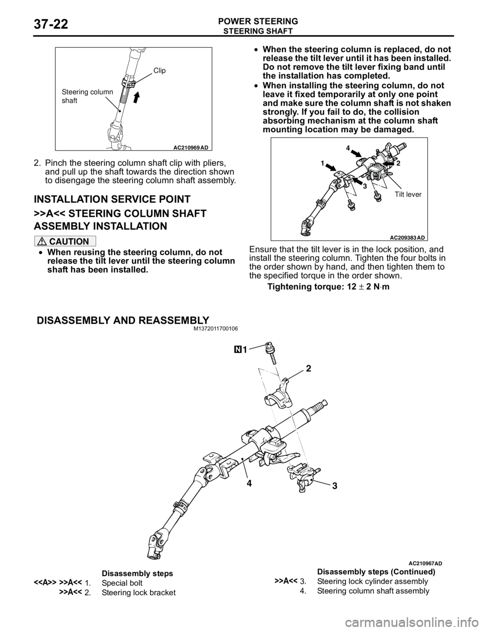
2. Pinch the steering column shaft clip with pliers,
and pull up the shaft towards the direction shown
to disengage the steering column shaft assembly.
INSTALLATION SERVICE POINT
>>A<< STEERING COLUMN SHAFT
ASSEMBLY INSTALLATION
CAUTION
•When reusing the steering column, do not
release the tilt lever until the steering column
shaft has been installed.•When the steering column is replaced, do not
release the tilt lever until it has been installed.
Do not remove the tilt lever fixing band until
the installation has completed.
•When installing the steering column, do not
leave it fixed temporarily at only one point
and make sure the column shaft is not shaken
strongly. If you fail to do, the collision
absorbing mechanism at the column shaft
mounting location may be damaged.
Ensure that the tilt lever is in the lock position, and
install the steering column. Tighten the four bolts in
the order shown by hand, and then tighten them to
the specified torque in the order shown.
Tightening torque: 12 ± 2 N⋅m
DISASSEMBLY AND REASSEMBLYM1372011700106
AC210969AD
Clip
Steering column
shaft
AC209383
AD
14
32
Tilt lever
AC210967AD
3 2 14
Disassembly steps
<> >>A<<1. Special bolt
>>A<<2. Steering lock bracket
>>A<<3. Steering lock cylinder assembly
4. Steering column shaft assemblyDisassembly steps (Continued)
Page 257 of 788
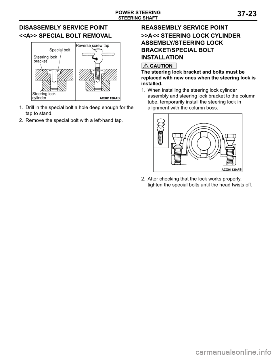
Page 258 of 788
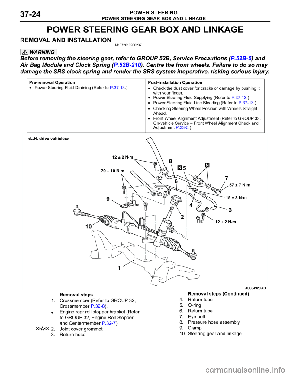
POWER STEERING GEAR BOX AND LINKAGE
POWER STEERING37-24
POWER STEERING GEAR BOX AND LINKAGE
REMOVAL AND INSTALLATIONM1372010900237
WARNING
Before removing the steering gear, refer to GROUP 52B, Service Precautions (P.52B-5) and
Air Bag Module and Clock Spring (P.52B-210). Centre the front wheels. Failure to do so may
damage the SRS clock spring and render the SRS system inoperative, risking serious injury.
Pre-removal Operation
•Power Steering Fluid Draining (Refer to P.37-13.)Post-installation Operation
•Check the dust cover for cracks or damage by pushing it
with your finger.
•Power Steering Fluid Supplying (Refer to P.37-13.)
•Power Steering Fluid Line Bleeding (Refer to P.37-13.)
•Checking Steering Wheel Position with Wheels Straight
Ahead.
•Front Wheel Alignment Adjustment (Refer to GROUP 33,
On-vehicle Service − Front Wheel Alignment Check and
Adjustment P.33-5.)
AC304920
AB
57 ± 7 N·m
15 ± 3 N·m 70 ± 10 N·m
7
3 8
5
6
9
1024
1
12 ± 2 N·m
12 ± 2 N·m
Removal steps
1. Crossmember (Refer to GROUP 32,
Crossmember P.32-8).
•Engine rear roll stopper bracket (Refer
to GROUP 32, Engine Roll Stopper
and Centermember P.32-7).
>>A<<2. Joint cover grommet
3. Return hose4. Return tube
5. O-ring
6. Return tube
7. Eye bolt
8. Pressure hose assembly
9. Clamp
10. Steering gear and linkageRemoval steps (Continued)
Page 259 of 788
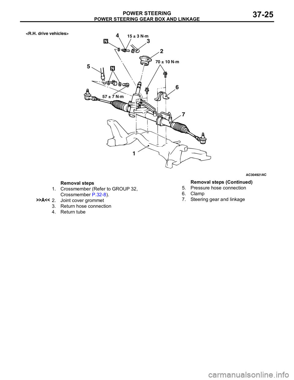
POWER STEERING GEAR BOX AND LINKAGE
POWER STEERING37-25
AC304921AC
57 ± 7 N·m15 ± 3 N·m
70 ± 10 N·m
3
52 4
1
6
7
Removal steps
1. Crossmember (Refer to GROUP 32,
Crossmember P.32-8).
>>A<<2. Joint cover grommet
3. Return hose connection
4. Return tube5. Pressure hose connection
6. Clamp
7. Steering gear and linkageRemoval steps (Continued)
Page 260 of 788
POWER STEERING GEAR BOX AND LINKAGE
POWER STEERING37-26
INSTALLATION SERVICE POINT
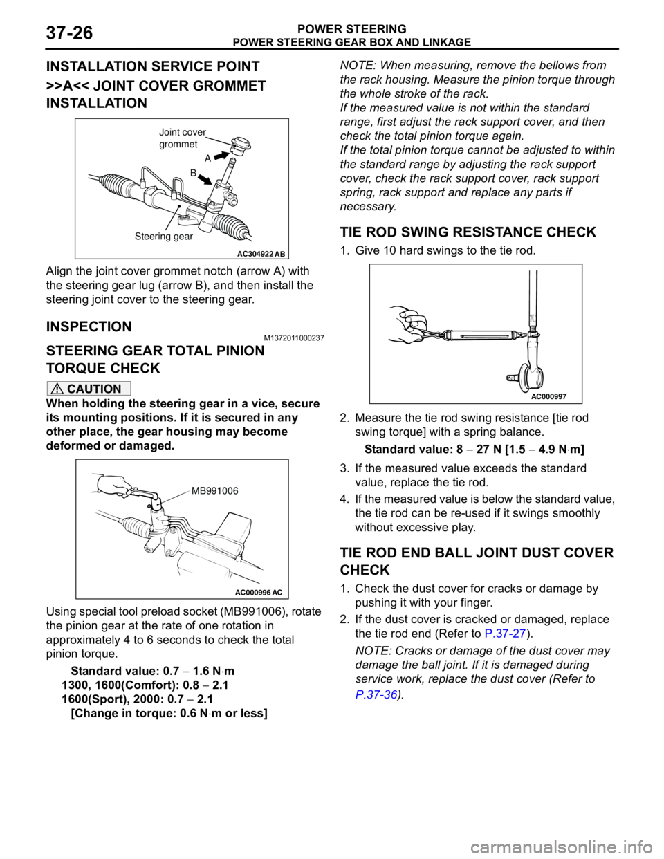
>>A<< JOINT COVER GROMMET
INSTALLATION
Align the joint cover grommet notch (arrow A) with
the steering gear lug (arrow B), and then install the
steering joint cover to the steering gear.
INSPECTIONM1372011000237
STEERING GEAR TOTAL PINION
TORQUE CHECK
CAUTION
When holding the steering gear in a vice, secure
its mounting positions. If it is secured in any
other place, the gear housing may become
deformed or damaged.
Using special tool preload socket (MB991006), rotate
the pinion gear at the rate of one rotation in
approximately 4 to 6 seconds to check the total
pinion torque.
Standard value: 0.7 − 1.6 N⋅m
1300, 1600(Comfort): 0.8 − 2.1
1600(Sport), 2000: 0.7 − 2.1
[Change in torque: 0.6 N⋅m or less]NOTE: When measuring, remove the bellows from
the rack housing. Measure the pinion torque through
the whole stroke of the rack.
If the measured value is not within the standard
range, first adjust the rack support cover, and then
check the total pinion torque again.
If the total pinion torque cannot be adjusted to within
the standard range by adjusting the rack support
cover, check the rack support cover, rack support
spring, rack support and replace any parts if
necessary.
TIE ROD SWING RESISTANCE CHECK
1. Give 10 hard swings to the tie rod.
2. Measure the tie rod swing resistance [tie rod
swing torque] with a spring balance.
Standard value: 8 − 27 N [1.5 − 4.9 N⋅m]
3. If the measured value exceeds the standard
value, replace the tie rod.
4. If the measured value is below the standard value,
the tie rod can be re-used if it swings smoothly
without excessive play.
TIE ROD END BALL JOINT DUST COVER
CHECK
1. Check the dust cover for cracks or damage by
pushing it with your finger.
2. If the dust cover is cracked or damaged, replace
the tie rod end (Refer to P.37-27).
NOTE: Cracks or damage of the dust cover may
damage the ball joint. If it is damaged during
service work, replace the dust cover (Refer to
P.37-36).
AC304922AB
A
B Joint cover
grommet
Steering gear
AC000996 AC
MB991006
AC000997