Side MITSUBISHI LANCER 2005 Repair Manual
[x] Cancel search | Manufacturer: MITSUBISHI, Model Year: 2005, Model line: LANCER, Model: MITSUBISHI LANCER 2005Pages: 788, PDF Size: 45.98 MB
Page 219 of 788
SHOCK ABSORBER ASSEMBLY
REAR SUSPENSION34-19
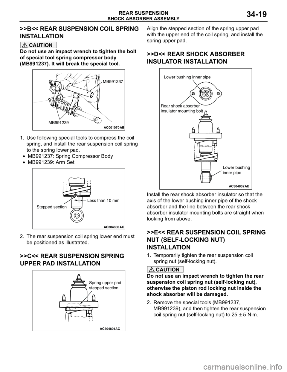
>>B<< REAR SUSPENSION COIL SPRING
INSTALLATION
CAUTION
Do not use an impact wrench to tighten the bolt
of special tool spring compressor body
(MB991237). It will break the special tool.
1. Use following special tools to compress the coil
spring, and install the rear suspension coil spring
to the spring lower pad.
•MB991237: Spring Compressor Body
•MB991239: Arm Set
2. The rear suspension coil spring lower end must
be positioned as illustrated.
>>C<< REAR SUSPENSION SPRING
UPPER PAD INSTALLATION
Align the stepped section of the spring upper pad
with the upper end of the coil spring, and install the
spring upper pad.
>>D<< REAR SHOCK ABSORBER
INSULATOR INSTALLATION
Install the rear shock absorber insulator so that the
axis of the lower bushing inner pipe of the shock
absorber and the line between the rear shock
absorber insulator mounting bolts are straight when
looking from above.
>>E<< REAR SUSPENSION COIL SPRING
NUT (SELF-LOCKING NUT)
INSTALLATION
1. Temporarily tighten the rear suspension coil
spring nut (self-locking nut).
CAUTION
Do not use an impact wrench to tighten the rear
suspension coil spring nut (self-locking nut),
otherwise the piston rod locking nut inside the
shock absorber will be damaged.
2. Remove the special tools (MB991237,
MB991239), and then tighten the rear suspension
coil spring nut (self-locking nut) to 25 ± 5 N⋅m.
AC001070
MB991237
MB991239
AB
AC304800AC
Less than 10 mm
Stepped section
AC304801AC
Spring upper pad
stepped section
AC304802
Lower bushing inner pipe
Rear shock absorber
insulator mounting bolt
AB
Lower bushing
inner pipe
Page 221 of 788
STABILIZER BAR
REAR SUSPENSION34-21
INSTALLATION SERVICE POINTS
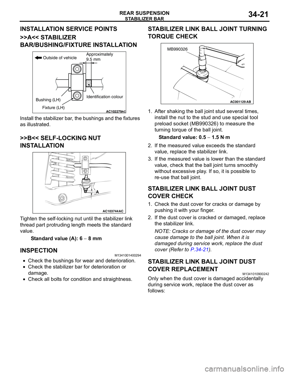
>>A<< STABILIZER
BAR/BUSHING/FIXTURE INSTALLATION
Install the stabilizer bar, the bushings and the fixtures
as illustrated.
>>B<< SELF-LOCKING NUT
INSTALLATION
Tighten the self-locking nut until the stabilizer link
thread part protruding length meets the standard
value.
Standard value (A): 6 − 8 mm
INSPECTIONM1341001400294
•Check the bushings for wear and deterioration.
•Check the stabilizer bar for deterioration or
damage.
•Check all bolts for condition and straightness.
STABILIZER LINK BALL JOINT TURNING
TORQUE CHECK
1. After shaking the ball joint stud several times,
install the nut to the stud and use special tool
preload socket (MB990326) to measure the
turning torque of the ball joint.
Standard value: 0.5 − 1.5 N⋅m
2. If the measured value exceeds the standard
value, replace the stabilizer link.
3. If the measured value is lower than the standard
value, check that the ball joint turns smoothly
without excessive play. If so, it is possible to
re-use that ball joint.
STABILIZER LINK BALL JOINT DUST
COVER CHECK
1. Check the dust cover for cracks or damage by
pushing it with your finger.
2. If the dust cover is cracked or damaged, replace
the stabilizer link.
NOTE: Cracks or damage of the dust cover may
cause damage to the ball joint. When it is
damaged during service work, replace the dust
cover (Refer to P.34-21).
STABILIZER LINK BALL JOINT DUST
COVER REPLACEMENT
M1341010900242
Only when the dust cover is damaged accidentally
during service work, replace the dust cover as
follows:
AC102279AC
Outside of vehicle
Bushing (LH)
Fixture (LH)Identification colourApproximately
9.5 mm
AC103744
A
AC
AC001129
MB990326
AB
Page 222 of 788
STABILIZER BAR
REAR SUSPENSION34-22
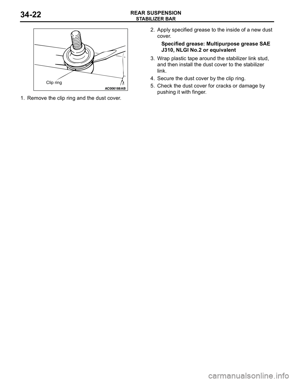
1. Remove the clip ring and the dust cover.2. Apply specified grease to the inside of a new dust
cover.
Specified grease: Multipurpose grease SAE
J310, NLGI No.2 or equivalent
3. Wrap plastic tape around the stabilizer link stud,
and then install the dust cover to the stabilizer
link.
4. Secure the dust cover by the clip ring.
5. Check the dust cover for cracks or damage by
pushing it with finger.
AC006188 AB
Clip ring
Page 226 of 788
GENERAL INFORMATION
PARKING BRAKES36-2
GENERAL INFORMATION
M1361000100496
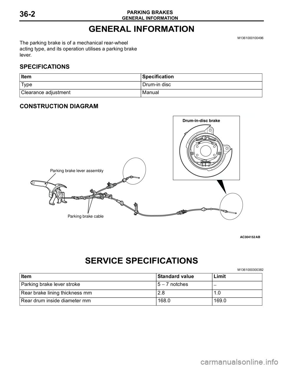
The parking brake is of a mechanical rear-wheel
acting type, and its operation utilises a parking brake
lever.
SPECIFICATIONS
CONSTRUCTION DIAGRAM
SERVICE SPECIFICATIONS
M1361000300382
Item Specification
Type Drum-in disc
Clearance adjustment Manual
AC211553
AC104333
AC304152
Parking brake lever assembly
Parking brake cable
AB
Drum-in-disc brake
Item Standard value Limit
Parking brake lever stroke 5 − 7 notches
−
Rear brake lining thickness mm 2.8 1.0
Rear drum inside diameter mm 168.0 169.0
Page 233 of 788
PARKING BRAKE LINING AND DRUM
PARKING BRAKES36-9
>>D<< SHOE RETURN SPRINGS
INSTALLATION
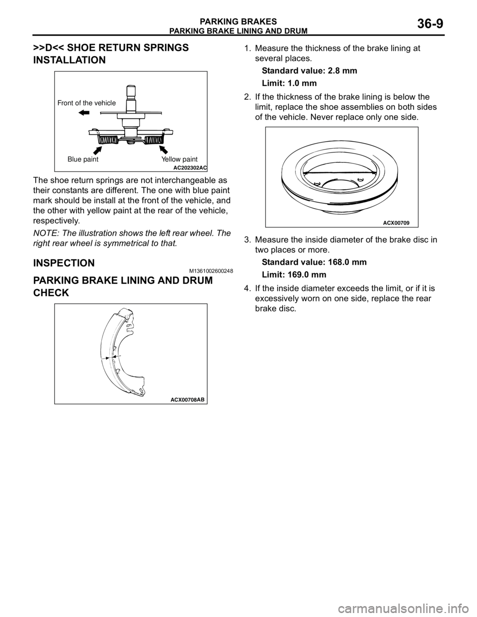
The shoe return springs are not interchangeable as
their constants are different. The one with blue paint
mark should be install at the front of the vehicle, and
the other with yellow paint at the rear of the vehicle,
respectively.
NOTE: The illustration shows the left rear wheel. The
right rear wheel is symmetrical to that.
INSPECTIONM1361002600248
PARKING BRAKE LINING AND DRUM
CHECK
1. Measure the thickness of the brake lining at
several places.
Standard value: 2.8 mm
Limit: 1.0 mm
2. If the thickness of the brake lining is below the
limit, replace the shoe assemblies on both sides
of the vehicle. Never replace only one side.
3. Measure the inside diameter of the brake disc in
two places or more.
Standard value: 168.0 mm
Limit: 169.0 mm
4. If the inside diameter exceeds the limit, or if it is
excessively worn on one side, replace the rear
brake disc.
AC202302AC
Front of the vehicle
Blue paint Yellow paint
ACX00708AB
ACX00709
Page 237 of 788

GENERAL INFORMATION
POWER STEERING37-3
GENERAL INFORMATION
M1372000100337
Power steering has been adopted in all vehicles to
make the steering system easier to handle.
FEATURES
•A 4-spoke steering wheel is used.
•MOMO leather-wrapped 3-spoke steering wheel
is used.
•A steering column has a shock absorbing
mechanism and a tilt steering mechanism.•Integral-type rack and pinion gear with high
rigidity and excellent response is used.
•A vane type pump with a fluid flow rate control
system which change steering effort according to
the engine speed is used.
•The separate plastic resin oil reservoir is used to
reduce weight and to make the fluid level
checking easier.
SPECIFICATIONS
Item Comfort Sport
Steering
wheelType 4-spoke type MOMO leather-wrapped
3-spoke type
Outside diameter mm 380 365
Maximum number of turns 3.19 2.86
3.08
Steering
columnColumn mechanism Shock absorbing mechanism and Tilt steering mechanism
Power steering type Integral type
Oil pump Type Vane pump
Basic discharge amount cm
3/rev.7.2 <1300, 1600>
8.1 <2000>7.2 <1300, 1600>
8.1 <2000>
Relief pressure MPa 8.8 8.8
Reservoir type Separate type (plastic)
Pressure switch Equipped
Steering
gearType Rack and pinion
Stroke ratio (Rack stroke/Steering
wheel maximum turning radius)45.74 45.74
Rack stroke mm 146 131
141
Page 242 of 788
SPECIAL TOOLS
POWER STEERING37-8
SPECIAL TOOLS
M1372000600354
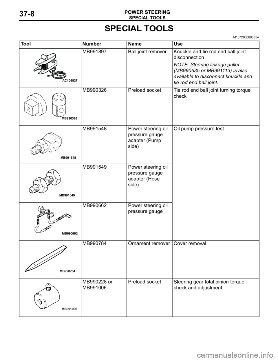
Tool Number Name Use
MB991897 Ball joint remover Knuckle and tie rod end ball joint
disconnection
NOTE: Steering linkage puller
(MB990635 or MB991113) is also
available to disconnect knuckle and
tie rod end ball joint.
MB990326 Preload socket Tie rod end ball joint turning torque
check
MB991548 Power steering oil
pressure gauge
adapter (Pump
side)Oil pump pressure test
MB991549 Power steering oil
pressure gauge
adapter (Hose
side)
MB990662 Power steering oil
pressure gauge
MB990784 Ornament remover Cover removal
MB990228 or
MB991006Preload socket Steering gear total pinion torque
check and adjustment
AC106827
MB990326
MB991548
MB991549
MB990662
MB990784
MB991006
Page 248 of 788
ON-VEHICLE SERVICE
POWER STEERING37-14
CAUTION
Perform air bleeding only while cranking the
engine. If air bleeding is performed while the
engine is running, air could enter the fluid.
During air bleeding, refill the steering fluid
supply so that the level never falls below the
"MIN" mark on the oil reservoir.
3. Turn the steering wheel all the way to the left and
right five or six times while using the starter motor
to crank the engine intermittently several times
(for 15 to 20 seconds).
4. Connect the ignition coil connectors (Refer to
GROUP 16, Ignition Coil P.16-38 or P.16-39).
5. Start the engine (idling).
6. Turn the steering wheel to the left and right until
there are no air bubbles in the oil reservoir.
7. Confirm that the fluid is not milky, and that the
level is between "MAX" and "MIN" marks.
8. Confirm that there is very little change in the fluid
level when the steering wheel is turned left and
right.
CAUTION
If the fluid level rises suddenly after the engine is
stopped, the air has not been completely bled. If
air bleeding is not complete, there will be
abnormal noises from the pump and the
flow-control valve, and this condition could
cause reduce the life of the power steering
components.
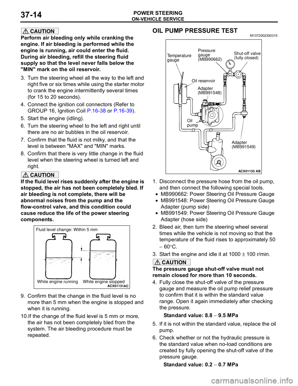
9. Confirm that the change in the fluid level is no
more than 5 mm when the engine is stopped and
when it is running.
10.If the change of the fluid level is 5 mm or more,
the air has not been completely bled from the
system. The air bleeding procedure must be
repeated.
OIL PUMP PRESSURE TESTM1372002300315
1. Disconnect the pressure hose from the oil pump,
and then connect the following special tools.
•MB990662: Power Steering Oil Pressure Gauge
•MB991548: Power Steering Oil Pressure Gauge
Adapter (pump side)
•MB991549: Power Steering Oil Pressure Gauge
Adapter (hose side)
2. Bleed air, then turn the steering wheel several
times while the vehicle is not moving so that the
temperature of the fluid rises to approximately 50
− 60°C.
3. Start the engine and idle it at 1000 ± 100 r/min.
CAUTION
The pressure gauge shut-off valve must not
remain closed for more than 10 seconds.
4. Fully close the shut-off valve of the pressure
gauge and measure the oil pump relief pressure
to confirm that it is within the standard value
range. Open it again immediately after checking
the pressure.
Standard value: 8.8 − 9.5 MPa
5. If it is not within the standard value, replace the oil
pump.
6. Check whether or not the hydraulic pressure is
the standard value when no-load conditions are
created by fully opening the shut-off valve of the
pressure gauge.
Standard value: 0.2 − 0.7 MPa
ACX01131While engine running While engine stoppedAC
Fluid level change: Within 5 mm
ACX01133
Temperature
gauge
Oil reservoir
Adapter
(MB991548)
Oil
pump
Adapter
(MB991549)
AB
Shut-off valve
(fully closed) Pressure
gauge
(MB990662)
Page 249 of 788
ON-VEHICLE SERVICE
POWER STEERING37-15
7. If it is not within the standard value, the probable
cause is a malfunction of the oil line or steering
gear, so check these parts and repair as
necessary.
8. Turn the steering wheel all the way to the left or
right; then check whether or not the retention
hydraulic pressure is the standard value.
Standard value: 8.8 − 9.5 MPa
9. If not the standard value, overhaul the steering
gear. Remeasure fluid pressure.
10. Remove the special tools, and then tighten the
pressure hose to the specified torque.
Tightening torque: 57 ± 7 N⋅m
11. Bleed the system (Refer to P.37-13).
POWER STEERING PRESSURE SWITCH
CHECK
M1372007200324
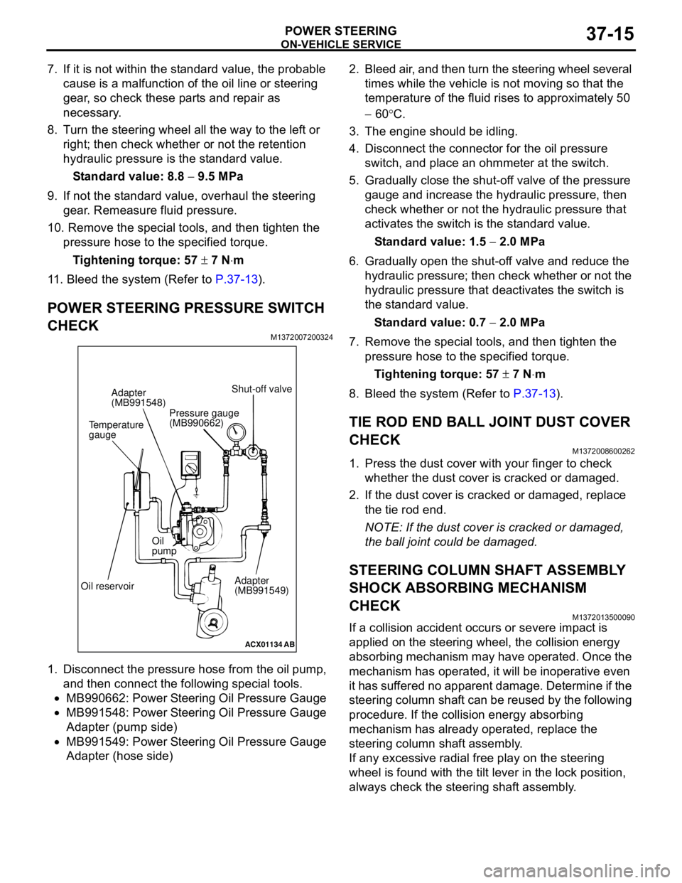
1. Disconnect the pressure hose from the oil pump,
and then connect the following special tools.
•MB990662: Power Steering Oil Pressure Gauge
•MB991548: Power Steering Oil Pressure Gauge
Adapter (pump side)
•MB991549: Power Steering Oil Pressure Gauge
Adapter (hose side)2. Bleed air, and then turn the steering wheel several
times while the vehicle is not moving so that the
temperature of the fluid rises to approximately 50
− 60°C.
3. The engine should be idling.
4. Disconnect the connector for the oil pressure
switch, and place an ohmmeter at the switch.
5. Gradually close the shut-off valve of the pressure
gauge and increase the hydraulic pressure, then
check whether or not the hydraulic pressure that
activates the switch is the standard value.
Standard value: 1.5 − 2.0 MPa
6. Gradually open the shut-off valve and reduce the
hydraulic pressure; then check whether or not the
hydraulic pressure that deactivates the switch is
the standard value.
Standard value: 0.7 − 2.0 MPa
7. Remove the special tools, and then tighten the
pressure hose to the specified torque.
Tightening torque: 57 ± 7 N⋅m
8. Bleed the system (Refer to P.37-13).
TIE ROD END BALL JOINT DUST COVER
CHECK
M1372008600262
1. Press the dust cover with your finger to check
whether the dust cover is cracked or damaged.
2. If the dust cover is cracked or damaged, replace
the tie rod end.
NOTE: If the dust cover is cracked or damaged,
the ball joint could be damaged.
STEERING COLUMN SHAFT ASSEMBLY
SHOCK ABSORBING MECHANISM
CHECK
M1372013500090
If a collision accident occurs or severe impact is
applied on the steering wheel, the collision energy
absorbing mechanism may have operated. Once the
mechanism has operated, it will be inoperative even
it has suffered no apparent damage. Determine if the
steering column shaft can be reused by the following
procedure. If the collision energy absorbing
mechanism has already operated, replace the
steering column shaft assembly.
If any excessive radial free play on the steering
wheel is found with the tilt lever in the lock position,
always check the steering shaft assembly.
ACX01134
AB
Temperature
gaugeAdapter
(MB991548)
Oil reservoirOil
pump
Adapter
(MB991549) Shut-off valve
Pressure gauge
(MB990662)
Page 266 of 788
POWER STEERING GEAR BOX AND LINKAGE
POWER STEERING37-32
REASSEMBLY SERVICE POINTS
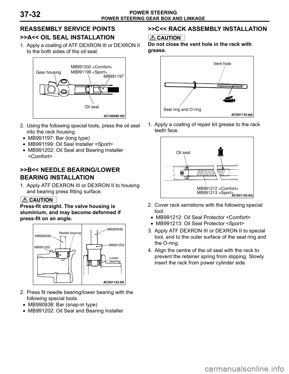
>>A<< OIL SEAL INSTALLATION
1. Apply a coating of ATF DEXRON III or DEXRON II
to the both sides of the oil seal.
2. Using the following special tools, press the oil seal
into the rack housing.
•MB991197: Bar (long type)
•MB991199: Oil Seal Installer
•MB991202: Oil Seal and Bearing Installer
>>B<< NEEDLE BEARING/LOWER
BEARING INSTALLATION
1. Apply ATF DEXRON III or DEXRON II to housing
and bearing press fitting surface.
CAUTION
Press-fit straight. The valve housing is
aluminium, and may become deformed if
press-fit on an angle.
2. Press fit needle bearing/lower bearing with the
following special tools.
•MB990938: Bar (snap-in type)
•MB991202: Oil Seal and Bearing Installer
>>C<< RACK ASSEMBLY INSTALLATION
CAUTION
Do not close the vent hole in the rack with
grease.
1. Apply a coating of repair kit grease to the rack
teeth face.
2. Cover rack serrations with the following special
tool.
•MB991212: Oil Seal Protector
•MB991213: Oil Seal Protector
3. Apply ATF DEXRON III or DEXRON II to special
tool, and to the outer surface of the seal ring and
the O-ring.
4. Align the centre of the oil seal with the rack to
prevent the retainer spring from slipping. Slowly
insert the rack from power cylinder side.
AC100260AD
MB991197
Oil seal MB991202
MB991199
Gear housing
ACX01153
Needle bearing
MB990938
MB991202MB991202
Lower
bearing
AE MB990938
ACX01154
AB
Seal ring and O-ringVent hole
ACX01155
MB991212
MB991213
AG
Oil seal