Side MITSUBISHI LANCER 2005 Repair Manual
[x] Cancel search | Manufacturer: MITSUBISHI, Model Year: 2005, Model line: LANCER, Model: MITSUBISHI LANCER 2005Pages: 788, PDF Size: 45.98 MB
Page 267 of 788
POWER STEERING GEAR BOX AND LINKAGE
POWER STEERING37-33
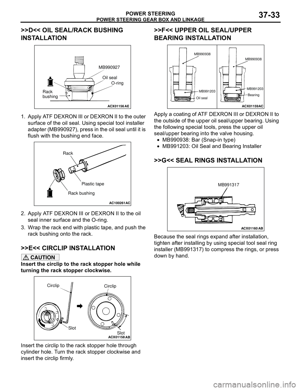
>>D<< OIL SEAL/RACK BUSHING
INSTALLATION
1. Apply ATF DEXRON III or DEXRON II to the outer
surface of the oil seal. Using special tool installer
adapter (MB990927), press in the oil seal until it is
flush with the bushing end face.
2. Apply ATF DEXRON III or DEXRON II to the oil
seal inner surface and the O-ring.
3. Wrap the rack end with plastic tape, and push the
rack bushing onto the rack.
>>E<< CIRCLIP INSTALLATION
CAUTION
Insert the circlip to the rack stopper hole while
turning the rack stopper clockwise.
Insert the circlip to the rack stopper hole through
cylinder hole. Turn the rack stopper clockwise and
insert the circlip firmly.
>>F<< UPPER OIL SEAL/UPPER
BEARING INSTALLATION
Apply a coating of ATF DEXRON III or DEXRON II to
the outside of the upper oil seal/upper bearing. Using
the following special tools, press the upper oil
seal/upper bearing into the valve housing.
•MB990938: Bar (Snap-in type)
•MB991203: Oil Seal and Bearing Installer
>>G<< SEAL RINGS INSTALLATION
Because the seal rings expand after installation,
tighten after installing by using special tool seal ring
installer (MB991317) to compress the rings, or press
down by hand.
ACX01156AE
Oil seal
O-ring MB990927
Rack
bushing
AC100261
AC
Rack
Plastic tape
Rack bushing
ACX01158
Circlip
Slot
AB
Circlip
Slot
ACX01159AC MB990938
MB991203
Oil seal
MB991203
Bearing MB990938
ACX01160AB
MB991317
Page 269 of 788
POWER STEERING GEAR BOX AND LINKAGE
POWER STEERING37-35
CAUTION
When adjusting, set at the highest value of the
standard value range.
NOTE: If the total pinion toque cannot be adjusted
to the standard value within the specified return
angle, check the rack support cover components
and replace any parts if necessary.
2. If the total pinion torque or the change in torque is
outside the standard value, move the rack support
cover 0 − 30°, and adjust the pinion torque again.
>>L<< TAB WASHER/TIE ROD
INSTALLATION
After installing the tie rod to the rack, fold tab washer
end (two locations) to tie rod notch.
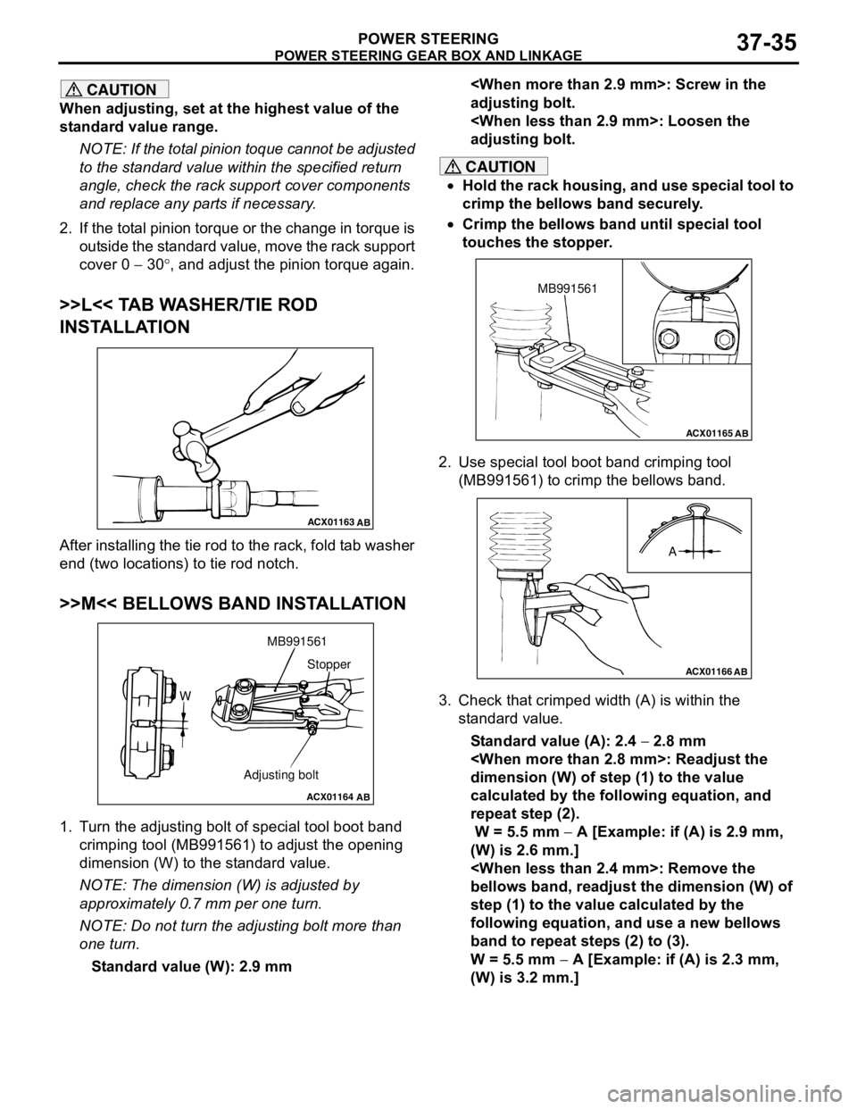
>>M<< BELLOWS BAND INSTALLATION
1. Turn the adjusting bolt of special tool boot band
crimping tool (MB991561) to adjust the opening
dimension (W) to the standard value.
NOTE: The dimension (W) is adjusted by
approximately 0.7 mm per one turn.
NOTE: Do not turn the adjusting bolt more than
one turn.
Standard value (W): 2.9 mm
adjusting bolt.
adjusting bolt.
CAUTION
•Hold the rack housing, and use special tool to
crimp the bellows band securely.
•Crimp the bellows band until special tool
touches the stopper.
2. Use special tool boot band crimping tool
(MB991561) to crimp the bellows band.
3. Check that crimped width (A) is within the
standard value.
Standard value (A): 2.4 − 2.8 mm
dimension (W) of step (1) to the value
calculated by the following equation, and
repeat step (2).
W = 5.5 mm − A [Example: if (A) is 2.9 mm,
(W) is 2.6 mm.]
bellows band, readjust the dimension (W) of
step (1) to the value calculated by the
following equation, and use a new bellows
band to repeat steps (2) to (3).
W = 5.5 mm − A [Example: if (A) is 2.3 mm,
(W) is 3.2 mm.]
ACX01163
AB
ACX01164
AB
WMB991561
Adjusting boltStopper
ACX01165AB
MB991561
ACX01166
AB
A
Page 270 of 788
POWER STEERING GEAR BOX AND LINKAGE
POWER STEERING37-36
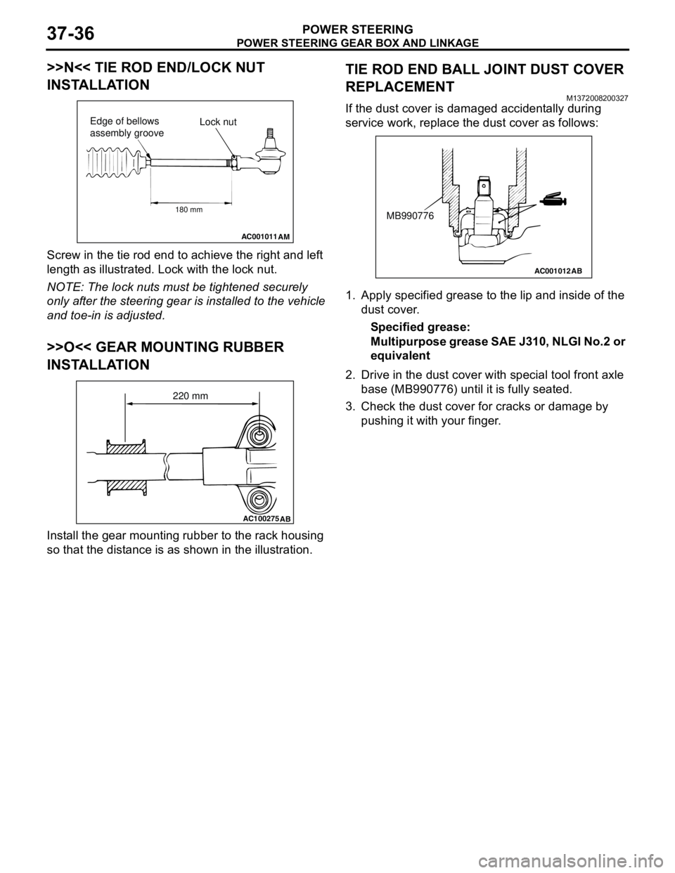
>>N<< TIE ROD END/LOCK NUT
INSTALLATION
Screw in the tie rod end to achieve the right and left
length as illustrated. Lock with the lock nut.
NOTE: The lock nuts must be tightened securely
only after the steering gear is installed to the vehicle
and toe-in is adjusted.
>>O<< GEAR MOUNTING RUBBER
INSTALLATION
Install the gear mounting rubber to the rack housing
so that the distance is as shown in the illustration.
TIE ROD END BALL JOINT DUST COVER
REPLACEMENT
M1372008200327
If the dust cover is damaged accidentally during
service work, replace the dust cover as follows:
1. Apply specified grease to the lip and inside of the
dust cover.
Specified grease:
Multipurpose grease SAE J310, NLGI No.2 or
equivalent
2. Drive in the dust cover with special tool front axle
base (MB990776) until it is fully seated.
3. Check the dust cover for cracks or damage by
pushing it with your finger.
AC001011
AM
Lock nut Edge of bellows
assembly groove
180 mm
AC100275
AB
220 mm
AC001012
AB
MB990776
Page 272 of 788
POWER STEERING OIL PUMP ASSEMBLY
POWER STEERING37-38
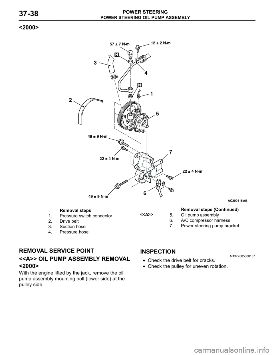
<2000>
REMOVAL SERVICE POINT
<> OIL PUMP ASSEMBLY REMOVAL
<2000>
With the engine lifted by the jack, remove the oil
pump assembly mounting bolt (lower side) at the
pulley side.
INSPECTIONM1372005300187
•Check the drive belt for cracks.
•Check the pulley for uneven rotation.
AC200116
AB
22 ± 4 N·m 12 ± 2 N·m
22 ± 4 N·m 49 ± 9 N·m57 ± 7 N·m
1
5 4 3
6 2
7
49 ± 9 N·m
Removal steps
1. Pressure switch connector
2. Drive belt
3. Suction hose
4. Pressure hose<>5. Oil pump assembly
6. A/C compressor harness
7. Power steering pump bracketRemoval steps (Continued)
Page 273 of 788
POWER STEERING OIL PUMP ASSEMBLY
POWER STEERING37-39
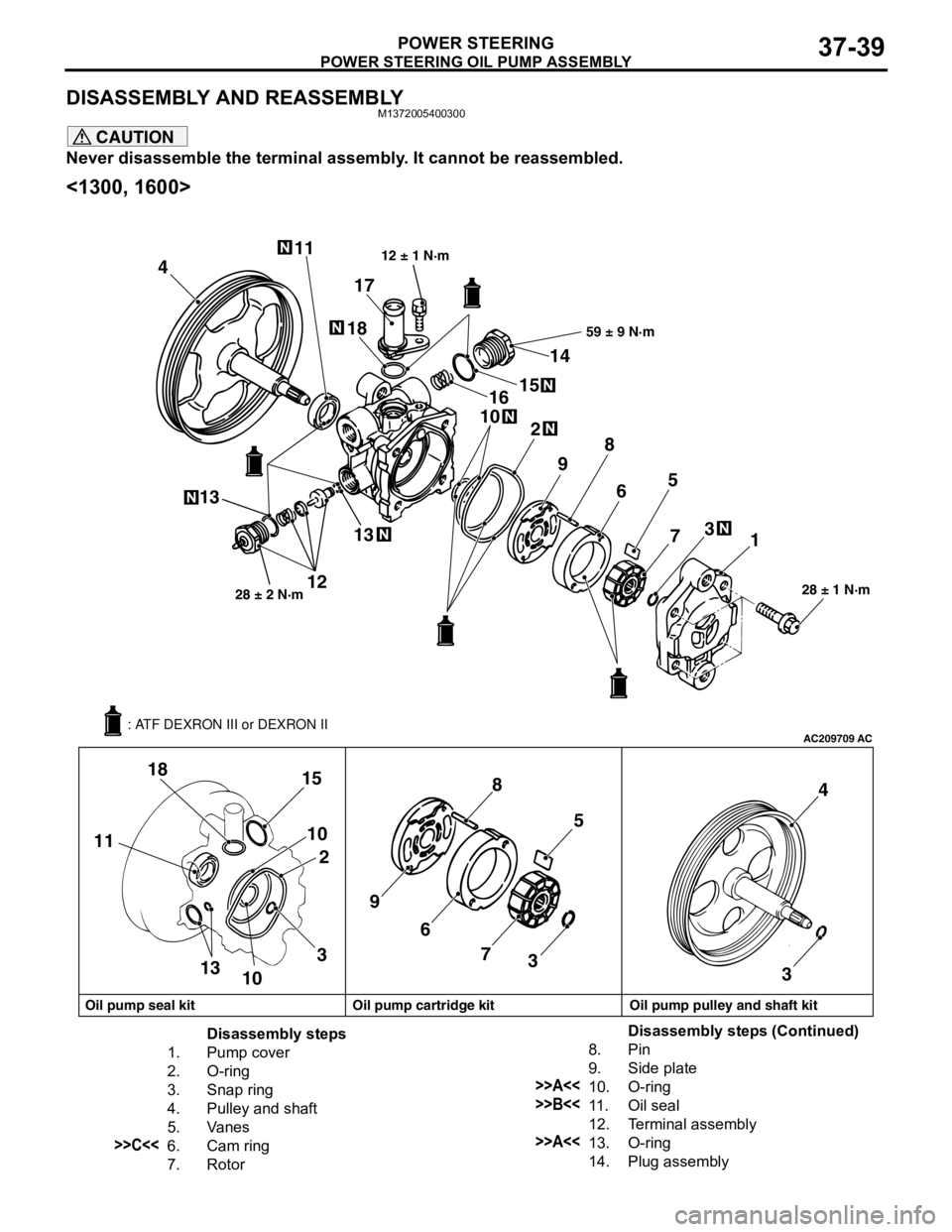
DISASSEMBLY AND REASSEMBLYM1372005400300
CAUTION
Never disassemble the terminal assembly. It cannot be reassembled.
<1300, 1600>
AC209709AC
411
1318
10
2
98
65
73
1
18
15
10
2 11
13
10398
65
7
34
3
28 ± 1 N·m
161514
59 ± 9 N·m
1228 ± 2 N·m
17
12 ± 1 N·m
13
Oil pump seal kit Oil pump cartridge kit Oil pump pulley and shaft kit: ATF DEXRON III or DEXRON II
Disassembly steps
1. Pump cover
2. O-ring
3. Snap ring
4. Pulley and shaft
5. Vanes
>>C<<6. Cam ring
7. Rotor8. Pin
9. Side plate
>>A<<10. O-ring
>>B<<11 . O i l s e a l
12. Terminal assembly
>>A<<13. O-ring
14. Plug assemblyDisassembly steps (Continued)
Page 274 of 788
POWER STEERING OIL PUMP ASSEMBLY
POWER STEERING37-40
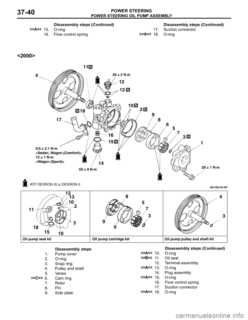
<2000>
>>A<<15. O-ring
16. Flow control springDisassembly steps (Continued)
17. Suction connector
>>A<<18. O-ringDisassembly steps (Continued)
AC100143AF
411
12
13
28 ± 2 N·m
102
9
8
6
5
7
3
1
28 ± 1 N·m
15
16
14
59 ± 9 N·m 9.9 ± 2.1 N·m
12 ± 1 N·m
18
17
5
7
3
98
6 3 13
10
2 13
10 15 18 114
3
Oil pump seal kit Oil pump cartridge kit Oil pump pulley and shaft kit
: ATF DEXRON III or DEXRON II
Disassembly steps
1. Pump cover
2. O-ring
3. Snap ring
4. Pulley and shaft
5. Vanes
>>C<<6. Cam ring
7. Rotor
8. Pin
9. Side plate
>>A<<10. O-ring
>>B<<11 . O i l s e a l
12. Terminal assembly
>>A<<13. O-ring
14. Plug assembly
>>A<<15. O-ring
16. Flow control spring
17. Suction connector
>>A<<18. O-ringDisassembly steps (Continued)
Page 275 of 788
POWER STEERING OIL PUMP ASSEMBLY
POWER STEERING37-41
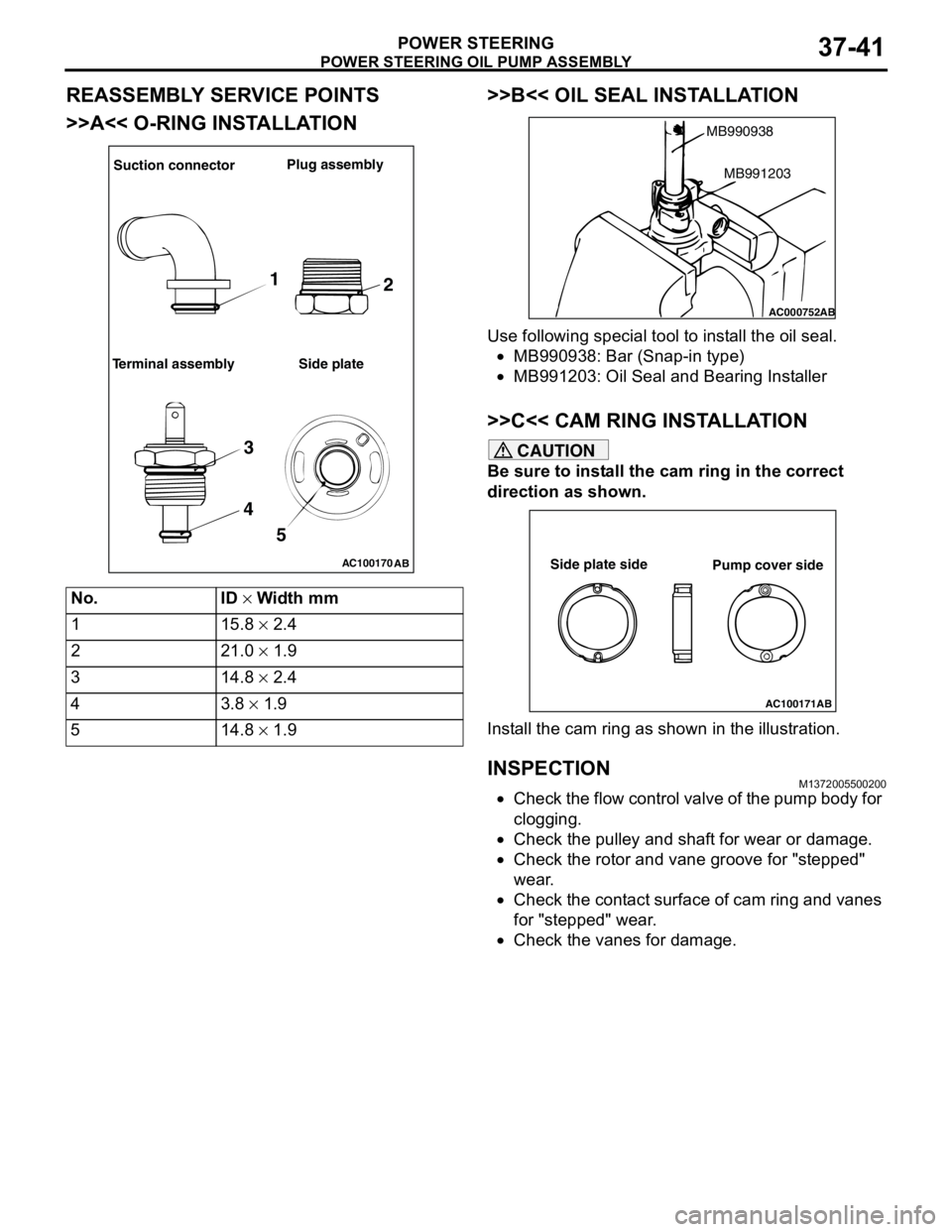
REASSEMBLY SERVICE POINTS
>>A<< O-RING INSTALLATION>>B<< OIL SEAL INSTALLATION
Use following special tool to install the oil seal.
•MB990938: Bar (Snap-in type)
•MB991203: Oil Seal and Bearing Installer
>>C<< CAM RING INSTALLATION
CAUTION
Be sure to install the cam ring in the correct
direction as shown.
Install the cam ring as shown in the illustration.
INSPECTIONM1372005500200
•Check the flow control valve of the pump body for
clogging.
•Check the pulley and shaft for wear or damage.
•Check the rotor and vane groove for "stepped"
wear.
•Check the contact surface of cam ring and vanes
for "stepped" wear.
•Check the vanes for damage. No. ID × Width mm
1 15.8 × 2.4
2 21.0 × 1.9
3 14.8 × 2.4
43.8 × 1.9
5 14.8 × 1.9
AC100170
AB
Suction connectorPlug assembly
Terminal assembly Side plate
1
2
3
4
5
AC000752
MB990938
AB
MB991203
AC100171AB
Side plate side
Pump cover side
Page 278 of 788
POWER STEERING HOSES
POWER STEERING37-44
REMOVAL SERVICE POINT
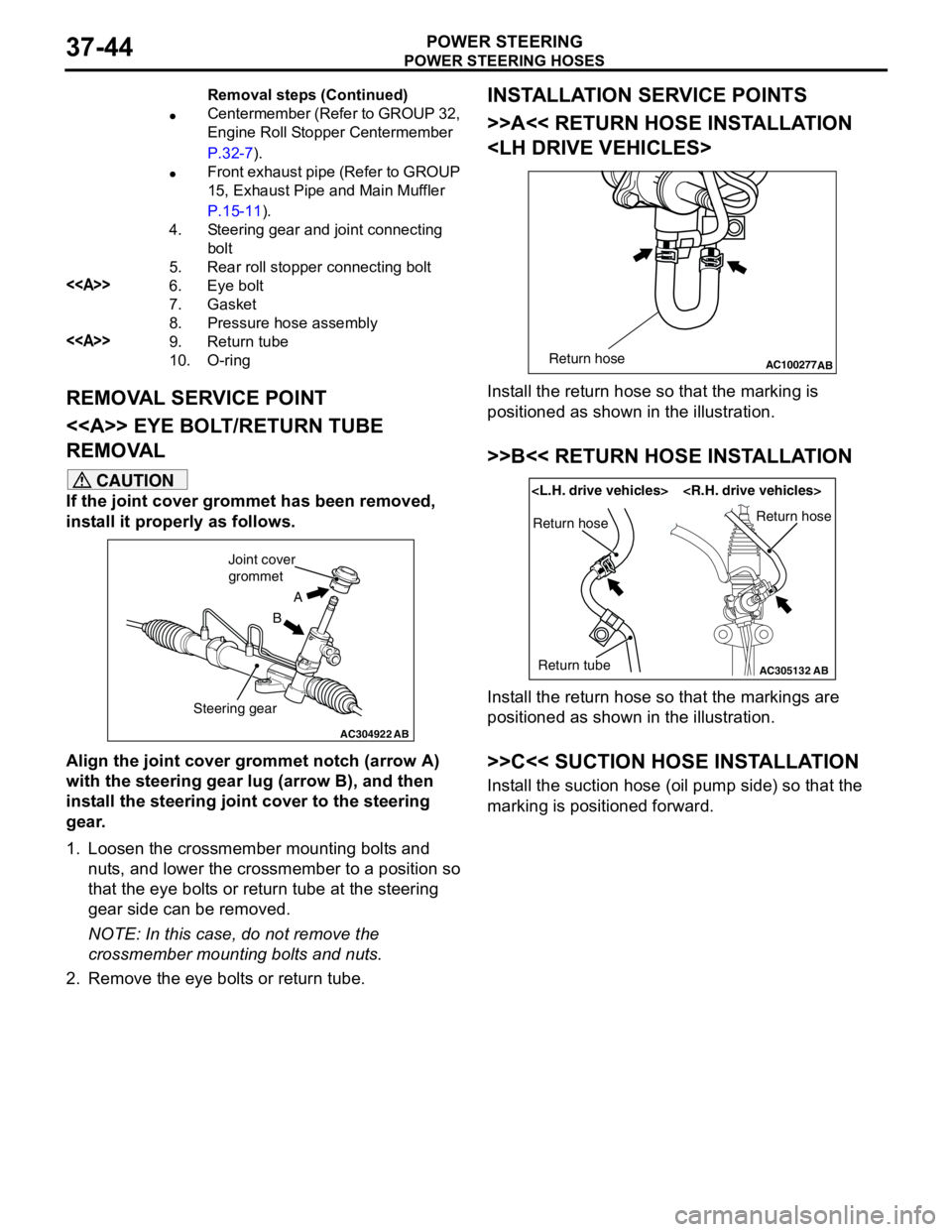
<> EYE BOLT/RETURN TUBE
REMOVAL
CAUTION
If the joint cover grommet has been removed,
install it properly as follows.
Align the joint cover grommet notch (arrow A)
with the steering gear lug (arrow B), and then
install the steering joint cover to the steering
gear.
1. Loosen the crossmember mounting bolts and
nuts, and lower the crossmember to a position so
that the eye bolts or return tube at the steering
gear side can be removed.
NOTE: In this case, do not remove the
crossmember mounting bolts and nuts.
2. Remove the eye bolts or return tube.
INSTALLATION SERVICE POINTS
>>A<< RETURN HOSE INSTALLATION
Install the return hose so that the marking is
positioned as shown in the illustration.
>>B<< RETURN HOSE INSTALLATION
Install the return hose so that the markings are
positioned as shown in the illustration.
>>C<< SUCTION HOSE INSTALLATION
Install the suction hose (oil pump side) so that the
marking is positioned forward.
•Centermember (Refer to GROUP 32,
Engine Roll Stopper Centermember
P.32-7).
•Front exhaust pipe (Refer to GROUP
15, Exhaust Pipe and Main Muffler
P.15-11).
4. Steering gear and joint connecting
bolt
5. Rear roll stopper connecting bolt
<>6. Eye bolt
7. Gasket
8. Pressure hose assembly
<>9. Return tube
10. O-ringRemoval steps (Continued)
AC304922AB
A
B Joint cover
grommet
Steering gear
AC100277
ABReturn hose
AC305132AB
Return hose
Return tubeReturn hose
Page 280 of 788
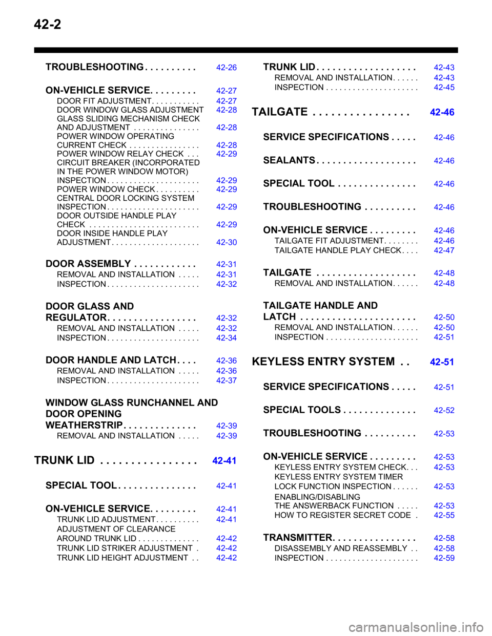
42-2
TROUBLESHOOTING . . . . . . . . . .42-26
ON-VEHICLE SERVICE. . . . . . . . .42-27
DOOR FIT ADJUSTMENT. . . . . . . . . . . 42-27
DOOR WINDOW GLASS ADJUSTMENT42-28
GLASS SLIDING MECHANISM CHECK
AND ADJUSTMENT . . . . . . . . . . . . . . . 42-28
POWER WINDOW OPERATING
CURRENT CHECK . . . . . . . . . . . . . . . . 42-28
POWER WINDOW RELAY CHECK . . . 42-29
CIRCUIT BREAKER (INCORPORATED
IN THE POWER WINDOW MOTOR)
INSPECTION . . . . . . . . . . . . . . . . . . . . . 42-29
POWER WINDOW CHECK . . . . . . . . . . 42-29
CENTRAL DOOR LOCKING SYSTEM
INSPECTION . . . . . . . . . . . . . . . . . . . . . 42-29
DOOR OUTSIDE HANDLE PLAY
CHECK . . . . . . . . . . . . . . . . . . . . . . . . . 42-29
DOOR INSIDE HANDLE PLAY
ADJUSTMENT . . . . . . . . . . . . . . . . . . . . 42-30
DOOR ASSEMBLY . . . . . . . . . . . .42-31
REMOVAL AND INSTALLATION . . . . . 42-31
INSPECTION . . . . . . . . . . . . . . . . . . . . . 42-32
DOOR GLASS AND
REGULATOR . . . . . . . . . . . . . . . . .
42-32
REMOVAL AND INSTALLATION . . . . . 42-32
INSPECTION . . . . . . . . . . . . . . . . . . . . . 42-34
DOOR HANDLE AND LATCH . . . .42-36
REMOVAL AND INSTALLATION . . . . . 42-36
INSPECTION . . . . . . . . . . . . . . . . . . . . . 42-37
WINDOW GLASS RUNCHANNEL AND
DOOR OPENING
WEATHERSTRIP . . . . . . . . . . . . . .
42-39
REMOVAL AND INSTALLATION . . . . . 42-39
TRUNK LID . . . . . . . . . . . . . . . .42-41
SPECIAL TOOL . . . . . . . . . . . . . . .
42-41
ON-VEHICLE SERVICE. . . . . . . . .42-41
TRUNK LID ADJUSTMENT . . . . . . . . . . 42-41
ADJUSTMENT OF CLEARANCE
AROUND TRUNK LID . . . . . . . . . . . . . . 42-42
TRUNK LID STRIKER ADJUSTMENT . 42-42
TRUNK LID HEIGHT ADJUSTMENT . . 42-42
TRUNK LID . . . . . . . . . . . . . . . . . . .42-43
REMOVAL AND INSTALLATION . . . . . . 42-43
INSPECTION . . . . . . . . . . . . . . . . . . . . . 42-45
TAILGATE . . . . . . . . . . . . . . . . 42-46
SERVICE SPECIFICATIONS . . . . .
42-46
SEALANTS . . . . . . . . . . . . . . . . . . .42-46
SPECIAL TOOL . . . . . . . . . . . . . . .42-46
TROUBLESHOOTING . . . . . . . . . .42-46
ON-VEHICLE SERVICE . . . . . . . . .42-46
TAILGATE FIT ADJUSTMENT. . . . . . . . 42-46
TAILGATE HANDLE PLAY CHECK . . . . 42-47
TAILGATE . . . . . . . . . . . . . . . . . . .42-48
REMOVAL AND INSTALLATION . . . . . . 42-48
TAILGATE HANDLE AND
LATCH . . . . . . . . . . . . . . . . . . . . . .
42-50
REMOVAL AND INSTALLATION . . . . . . 42-50
INSPECTION . . . . . . . . . . . . . . . . . . . . . 42-51
KEYLESS ENTRY SYSTEM . . 42-51
SERVICE SPECIFICATIONS . . . . .
42-51
SPECIAL TOOLS . . . . . . . . . . . . . .42-52
TROUBLESHOOTING . . . . . . . . . .42-53
ON-VEHICLE SERVICE . . . . . . . . .42-53
KEYLESS ENTRY SYSTEM CHECK. . . 42-53
KEYLESS ENTRY SYSTEM TIMER
LOCK FUNCTION INSPECTION . . . . . . 42-53
ENABLING/DISABLING
THE ANSWERBACK FUNCTION . . . . . 42-53
HOW TO REGISTER SECRET CODE . 42-55
TRANSMITTER. . . . . . . . . . . . . . . .42-58
DISASSEMBLY AND REASSEMBLY . . 42-58
INSPECTION . . . . . . . . . . . . . . . . . . . . . 42-59
Page 283 of 788
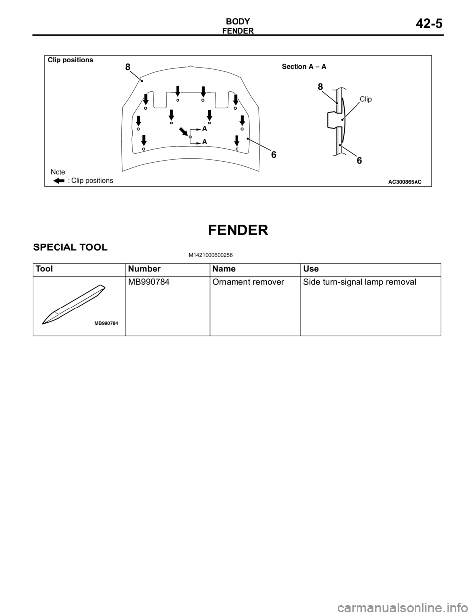
FENDER
BODY42-5
FENDER
SPECIAL TOOLM1421000600256
AC300865
Note
: Clip positions
Section A – A
AC
Clip
A
A
6 8
6 8
Clip positions
Tool Number Name Use
MB990784 Ornament remover Side turn-signal lamp removal
MB990784