sensor MITSUBISHI LANCER EVOLUTION 2007 Service Workshop Manual
[x] Cancel search | Manufacturer: MITSUBISHI, Model Year: 2007, Model line: LANCER EVOLUTION, Model: MITSUBISHI LANCER EVOLUTION 2007Pages: 1449, PDF Size: 56.82 MB
Page 441 of 1449

ENGINE -Timing Belt and Timing Belt B11A-35
12
1314 1516
8.8±1.0 N·m
162±5 N·m 19±3 N·m
(Engine oil)
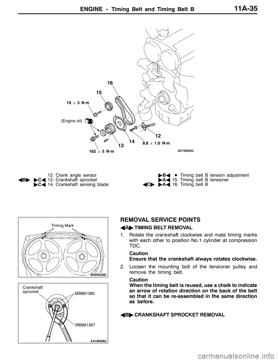
12. Crank angle sensor
AB""CA13. Crankshaft sprocket
"CA14. Crankshaft sensing blade"BADTiming belt B tension adjustment
"AA15. Timing belt B tensioner
AC""AA16. Timing belt B
REMOVAL SERVICE POINTS
AA"TIMING BELT REMOVAL
1. Rotate the crankshaft clockwise and mate timing marks
with each other to position No.1 cylinder at compression
TDC.
Caution
Ensure that the crankshaft always rotates clockwise.
2. Loosen the mounting bolt of the tensioner pulley and
remove the timing belt.
Caution
When the timing belt is reused, use a chalk to indicate
an arrow of rotation direction on the back of the belt
so that it can be re-assembled in the same direction
as before.
AB"CRANKSHAFT SPROCKET REMOVALTiming Mark
MB991367
Crankshaft
sprocket
MB991385
Page 450 of 1449

ENGINE -Engine Assembly11A-44
1
2
3 4
5
67
8
910
11 12
13
14
26±5 N·m
14±3 N·m
1516
18
5.0±1.0 N·m
1
5.0±1.0 N·m
11±1 N·m
17
Removal steps
1. Ignition coil connector
2. Crank angle sensor connector
3. Oxygen sensor connector
4. Fuel pressure solenoid valve
connector
5. Detonation sensor connector
6. Purge control solenoid valve
connector
7. Throttle position sensor connector
8. Idle speed control servo connector
9. Injector connector
10. Camshaft position sensor connector11. Engine coolant temperature gauge
unit connector
12. Engine coolant temperature sensor
connector
13. Alternator connector
14. EGR solenoid valve connector
15. Secondary air control solenoid valve
connector
16. Engine oil pressure switch
connector
17. Waste gate actuator mounting bolt
AA"18. Drive belt
Page 459 of 1449

ENGINE OVERHAUL -Specifications11B-5
MACHINING STANDARDS
Unit: mm
Items
Standard valueLimited value
Cylinder head, valve
Cylinder head
Oversize valve guide hole diameter
0.05 O.S.
0.25 O.S.
0.50 O.S.
Oversize valve seat hole diameter
Intake
0.3 O.S.
0.6 O.S.
Exhaust
0.3 O.S.
0.6 O.S.
12.05 - 12.07
12.25 - 12.27
12.50 - 12.52
35.30 - 35.33
35.60 - 35.63
33.30 - 33.33
33.60 - 33.63-
-
-
-
-
-
-
TIGHTENING TORQUE
ItemsTightening torque N·m
Alternator, ignition system
Oil level gauge guide bolt13±1
Water pump pulley bolt8.8±1.0
Alternator brace bolt (flange)23±3
Alternator brace bolt (washer)22±4
Alternator nut44±10
Crankshaft pulley bolt25±4
Center cover bolt3±0.5
Ignition coil bolt10±2
Spark plug25±5
Connector bracket bolt8.8±1.0
Timing belt
Timing belt cover bolt (flange)11±1
Timing belt cover bolt (washer)9±1
Power steering pump bracket bolt49±9
Tensioner pulley bolt49±6
Tensioner arm bolt21±4
Auto tensioner bolt23±3
Idler pulley bolt35±6
Crank angle sensor bolt8.8±1.0
Oil pump sprocket nut54±5
Crankshaft bolt162±5
Tensioner B bolt19±3
Counter balance shaft sprocket bolt46±3
Rocker cover bolt3.5±0.5
Engine support bracket bolt49±5
Page 460 of 1449

ENGINE OVERHAUL -Specifications11B-6
Items Tightening torque N·m
Camshaft sprocket bolt88±10
Fuel system
Throttle body bolt19±3
EGR valve bolt20±2
Fuel pressure regulator bolt8.8±2.0
Delivery pipe and injector bolt11±1
Vacuum hose and pipe bolt11±1
Solenoid assembly bolt9±1
Vacuum tank bracket bolt9±1
Secondary air system, intake manifold
Exhaust manifold heat protector bolt14±1
Vacuum hose and pipe bolt11±1
Air pipe assembly bolt (eye bolt)49±5
Air pipe assembly bolt (M6 flange)11±1
Air pipe assembly bolt (M8 flange)24±3
Air pipe assembly bolt (M8 washer)14±1
Air control valve assembly bolt22±4
Air control valve bracket bolt22±4
MDP sensor bolt5±1
Intake manifold stay bolt31±3
Intake manifold bolt (M8)20±2
Intake manifold bolt nut (M8)36±6
Exhaust manifold
Engine hanger bolt19±3
Turbocharger heat protector bolt14±1
O2sensor44±5
Exhaust fitting bracket bolt47±6
Exhaust fitting bolt nut59±5
Air outlet fitting bolt19±1
Oil return pipe bolt (flange)14±1
Oil return pipe bolt (washer)9±1
Turbocharger assembly and pipe bolt, nut59±5
Oil pipe bolt (M10 eye bolt)17±2
Oil pipe bolt (M12 eye bolt)31±2
Oil pipe bolt (M12 flange)11±1
Water pipe bolt (flange)10±1
Water pipe bolt (eye bolt)42±7
Exhaust manifold nut (M8)33±6
Exhaust manifold nut (M10)55±10
Water pump, water hose
Engine coolant temperature sensor29±10
Engine coolant temperature gauge unit10.8±1.0
Page 461 of 1449

ENGINE OVERHAUL -Specifications11B-7
Items Tightening torque N·m
Water outlet fitting bolt10±1
Thermostat housing bolt23±4
Water inlet pipe bolt (M6)10±1
Water inlet pipe bolt (M8)13±2
Water pump bolt14±1
Knock sensor23±2
Rocker arm, camshaft
Cam position sensor bolt8.8±1.0
Cover bolt10±2
Cam position sensing cylinder bolt22±4
Cam position sensor support bolt14±1
Bearing cap bolt20±1
Oil delivery body bolt11±1
Cylinder head, valve
Cylinder head bolt78±2→Completely loosen→20±2→90_+90_
Oil pump, oil pan
Drain plug39±5
Oil pan bolt9±3
Oil screen bolt19±3
Baffle plate bolt22±4
Oil pressure switch19±3
Oil cooler bypass valve54±5
Relief plug44±5
Oil filter bracket bolt19±3
Plug cap23±3
Flange bolt36±3
Oil pump case bolt23±3
Oil pump cover bolt17±1
Oil pump cover screw10±2
Piston, connecting rod
Connecting rod cap nut20±2+90_-94_
Crankshaft, cylinder block
Flywheel bolt132±5
Rear plate bolt11±1
Bell housing cover bolt9±1
Rear oil seal case bolt11±1
Beam bearing cap bolt25±2+90_- 100_
Check valve32±2
Throttle body
Throttle position sensor bolt2.0±0.5
Turbocharger
Waste gate actuator bolt11.3±1.5
Page 462 of 1449

ENGINE OVERHAUL -Specifications11B-8
SEALANTS
ItemSpecified sealantQuantity
Engine support bracket bolt3MTMAAD Part No. 8672 or equivalentAs required
Semi-circular packing3MTMAAD Part No. 8672 or equivalentAs required
Rocker cover3MTMAAD Part No. 8672 or equivalentAs required
Water outlet fittingMitsubishi Genuine Part No. MD970389 or
equivalentAs required
Engine coolant temperature gauge unit3MTMAAD Part No. 8672 or equivalentAs required
Engine coolant temperature sensor3MTMAAD Part No. 8672 or equivalentAs required
Cylinder head (camshaft bearing cap mounting
section)3MTMAAD Part No. 8672 or equivalentAs required
Cam position sensor supportMitsubishi Genuine Part No. MD970389 or
equivalentAs required
Oil pressure switch3MTMAAD Part No. 8672 or equivalentAs required
Oil panMitsubishi Genuine Part No. MD970389 or
equivalentAs required
Oil seal caseMitsubishi Genuine Part No. MD970389 or
equivalentAs required
FORM-IN-PLACE-GASKET
FIPG is used for several members of this engine. With this gasket, caution is required to the application
amount, application procedure and state of the application surface so that the performance is sufficiently
attained.
If sufficient gasket is not applied, leaks could occur, and if too much is applied, the gasket could protrude
and plug or restrict the oil and water flow passage. Thus, to prevent leaks from the joined sections,
it is absolutely necessary to evenly apply the correct amount.
The FIPG used for the engine parts reacts with moisture in the air and hardens so use it for the normal
metal flange parts.
DISASSEMBLY
The parts assembled with FIPG can be easily disassembled without special means. However, in some
cases, the sealant on the seams must be broken by lightly tapping with a wood hammer or similar tool.
A smooth and thin gasket scraper can be lightly tapped into the seams but in this case, take care not
to damage the seams.
The special tool oil pan remover (MD998727) is set for this purpose.
WASHING THE GASKET SURFACE
Completely remove all matters adhered on the gasket surfaces with a gasket scraper or wire brush.
Confirm that the FIPG application surface is smooth. There must be no grease or foreign matter on
the gasket surface.
Always remove the old FIPG that has entered the mounting holes and screw holes.
APPLICATION PROCEDURES
Apply an even coat of FIPG within the predetermined radius. Completely cover the areas around the
mounting holes. The FIPG can be wiped off if it has not hardened. Install at the set position while the
FIPG is still wet (within 15 minutes). When installing, maker sure that the FIPG does not get on areas
other than the required areas. After installing, do not subject the application areas to oil or water or
start the engine until the FIPG has sufficiently hardened (approx. one hour). The FIPG application procedures
differ according to the member, so follow the procedures given in this manual and apply the FIPG.
Page 467 of 1449

ENGINE OVERHAUL -Timing Belt11B-13
TIMING BELT
REMOVAL AND INSTALLATION
1
11±1N•m
2
3
4 56
7
8
910
11 1213
14 15
16 1718
192021 2223
2425
26
27
2829
30
313233
34
35
49±6N•m
21±4N•m
23±3N•m
11±1N•m11±1N•m
88±10 N•m
35±6N•m
54±5N•m 19±3N•m 46±3N•m 9±1N•m162±5N•m3.5±0.5 N•m
49±9N•m
8.8±1.0 N•m 49±5N•m
Removal steps
1. Timing belt front upper cover
2. Timing belt front center cover
3. Timing belt front lower cover
4. Power steering pump bracket
AA""MA5. Timing belt
"LA6. Tensioner pulley
7. Tensioner arm
"KA8. Auto tensioner
9. Idler pulley
10. Crank angle sensor
AB""JA11. Oil pump sprocket
AC""IA12. Crankshaft bolt
AD""IA13. Crankshaft sprocket
"IA14. Crankshaft sensing blade
15. Tensioner B
AE""HA16. Timing belt B
AF""GA17. Counter balance shaft sprocket
"FA18. SpacerAG""EA19. Crankshaft sprocket B
20. Crankshaft key
21. Breather hose
22. PCV hose
23. PCV valve
24. PCV valve gasket
25. Oil filler cap
"DA26. Rocker cover
"DA27. Rocker cover gasket A
28. Rocker cover gasket B
"CA29. Semi-circular packing
"BA30. Engine support bracket
AH""AA31. Camshaft sprocket bolt
32. Camshaft sprocket
33. Timing belt rear right cover
34. Timing belt rear left upper cover
35. Timing belt rear left lower cover
Page 482 of 1449

ENGINE OVERHAUL -Secondary Air System and Intake Manifold11B-28
SECONDARY AIR SYSTEM AND INTAKE MANIFOLD
REMOVAL AND INSTALLATION
1
11±1N•m
23 4 5
6
7
8
9
10 1112
13
11±1N•m24±3N•m
14±1N•m
31±3N•m5±1N•m
20±2N•m
22±4N•m
36±6N•m23±4N•m
14±1N•m
36±6N•m
36±6N•m22±4N•m
49±5N•m
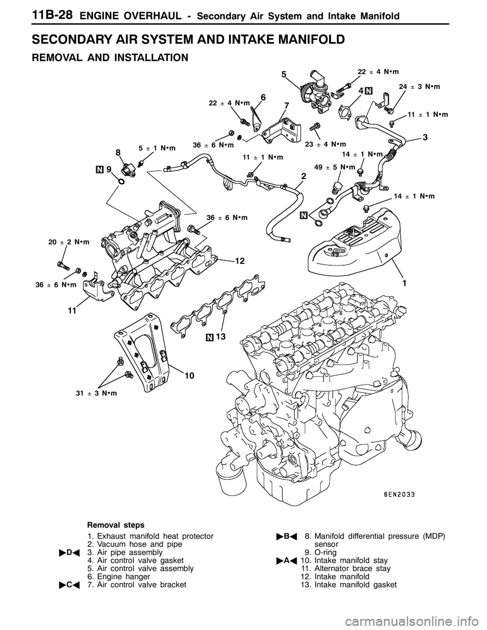
Removal steps
1. Exhaust manifold heat protector
2. Vacuum hose and pipe
"DA3. Air pipe assembly
4. Air control valve gasket
5. Air control valve assembly
6. Engine hanger
"CA7. Air control valve bracket"BA8. Manifold differential pressure (MDP)
sensor
9. O-ring
"AA10. Intake manifold stay
11. Alternator brace stay
12. Intake manifold
13. Intake manifold gasket
Page 483 of 1449

ENGINE OVERHAUL -Secondary Air System and Intake Manifold11B-29
INSTALLATION SERVICE POINTS
"AAINTAKE MANIFOLD STAY INSTALLATION
Check that the intake manifold stay is seated against the
intake manifold and cylinder block boss, and then tighten
at the specified torque 31±3N•m.
"BAMANIFOLD DIFFERENTIAL PRESSURE (MDP)
SENSOR INSTALLATION
Caution
Make sure not to apply impact against the sensor when
installing.
Do not use a sensor that has been dropped.
"CAAIR CONTROL VALVE BRACKET INSTALLATION
1. Temporarily tighten the air control valve bracket and
engine hanger with the bolt for tightening with the intake
manifold.
2. Tighten the bolt 1 shown in the illustration at the specified
torque 23±4N•m.
3. Tighten the bolt 2 shown in the illustration at the specified
torque 36±6N•m.
4. Tighten the bolt 3 shown in the illustration with the engine
hanger at the specified torque 22±4N•m.
"DAAIR PIPE ASSEMBLY INSTALLATION
1. Temporarily tighten air pipe assembly onto the air control
valve.
2. Tighten the bolts 1 and 2 shown in the illustration to
the exhaust manifold at the specified torque 49±5N•m.
3. Tighten the bolt 3 shown in the illustration to the air control
valve at the specified torque 24±3N•m.
4. Tighten the bolt 4 shown in the illustration to the cam
position sensor support at the specified toque 11±1
N•m.
5. Tighten the bolt 5 shown in the illustration to the exhaust
manifold at the specified torque 14±1N•m.
Intake manifold stay
1
23
1
5
23
4
Page 484 of 1449

ENGINE OVERHAUL -Exhaust Manifold11B-30
EXHAUST MANIFOLD
REMOVAL AND INSTALLATION
1
17±2N•m
2 3
45
6
78
910
11 1213
11±1N•m
14±1N•m 59±5N•m
9±1N•m 10±1N•m 44±5N•m
31±2N•m
42±7N•m 10±1N•m
55±10 N•m59±5N•m
19±1N•m 14±1N•m
42±7N•m
19±3N•m18 19
14
15
16
17
33±6N•m
47±6N•m
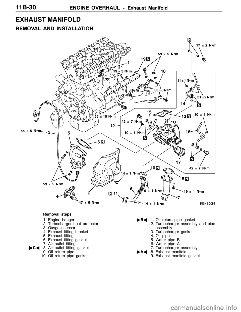
Removal steps
1. Engine hanger
2. Turbocharger heat protector
3. Oxygen sensor
4. Exhaust fitting bracket
5. Exhaust fitting
6. Exhaust fitting gasket
7. Air outlet fitting
"CA8. Air outlet fitting gasket
9. Oil return pipe
10. Oil return pipe gasket"BA11. Oil return pipe gasket
12. Turbocharger assembly and pipe
assembly
13. Turbocharger gasket
14. Oil pipe
15. Water pipe B
16. Water pipe A
17. Turbocharger assembly
"AA18. Exhaust manifold
19. Exhaust manifold gasket