MITSUBISHI LANCER EVOLUTION X 2008 Workshop Manual
Manufacturer: MITSUBISHI, Model Year: 2008, Model line: LANCER EVOLUTION X, Model: MITSUBISHI LANCER EVOLUTION X 2008Pages: 241, PDF Size: 8.26 MB
Page 101 of 241
SENSOR
MULTIPORT FUEL SYSTEM (MFI)13A-8
SENSORM2132001000565.
MASS AIRFLOW SENSOR
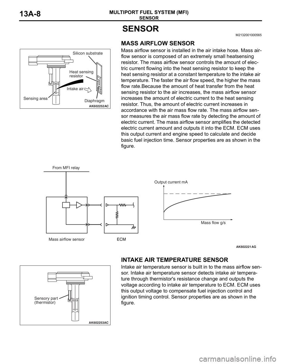
Mass airflow sensor is installed in the air intake hose. Mass air-
flow sensor is composed of an extremely small heatsensing
resistor. The mass airflow sensor controls the amount of elec
-
tric current flowing into the heat sensing resistor to keep the
heat sensing resistor at a constant temperature to the intake air
temperature. The faster the air flow speed, the higher the mass
flow rate.Because the amount of heat transfer from the heat
sensing resistor to the air increases, the mass airflow sensor
increases the amount of electric current to the heat sensing
resistor. Thus, the amount of electric current increases in
accordance with the air mass flow rate. The mass airflow sen
-
sor measures the air mass flow rate by detecting the amount of
electric current. The mass airflow sensor amplifies the detected
electric current amount and outputs it into the ECM. ECM uses
this output current and engine speed to calculate and decide
basic fuel injection time. Sensor properties are as shown in the
figure.
.
INTAKE AIR TEMPERATURE SENSOR
Intake air temperature sensor is built in to the mass airflow sen-
sor. Intake air temperature sensor detects intake air tempera-
ture through thermistor's resistance change and outputs the
voltage according to intake air temperature to ECM. ECM uses
this output voltage to compensate fuel injection control and
ignition timing control. Sensor properties are as shown in the
figure.
AK602252AC
Sensing areaSilicon substrate
Heat sensing
resistor
Intake air
Diaphragm
AK602221AG
From MFI relay
Mass airflow sensorECMOutput current mA
Mass flow g/s
AK602253AC
Sensory part
(thermistor)
Page 102 of 241
SENSOR
MULTIPORT FUEL SYSTEM (MFI)13A-9
.
MANIFOLD ABSOLUTE PRESSURE SENSOR
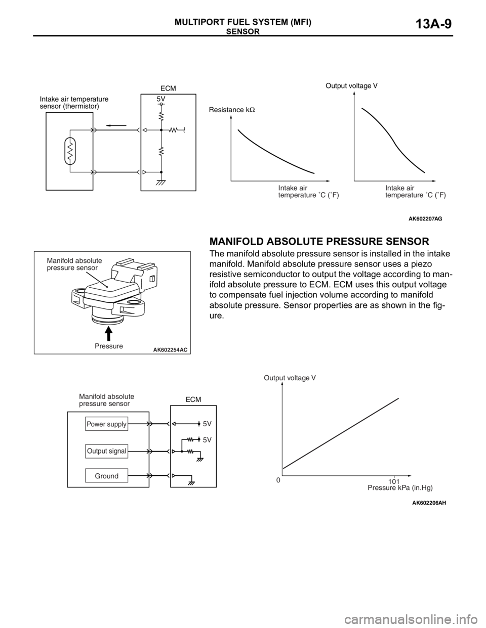
The manifold absolute pressure sensor is installed in the intake
manifold. Manifold absolute pressure sensor uses a piezo
resistive semiconductor to output the voltage according to man
-
ifold absolute pressure to ECM. ECM uses this output voltage
to compensate fuel injection volume according to manifold
absolute pressure. Sensor properties are as shown in the fig
-
ure.
.
AK602207
Intake air
temperature �C (�F)
AG
Resistance kΩOutput voltage V
Intake air temperature
sensor (thermistor)5V
Intake air
temperature �C (�F) ECM
AK602254 ACPressure Manifold absolute
pressure sensor
AK602206AH
5V
0
101 5V
GroundOutput voltage V
Pressure kPa (in.Hg) Manifold absolute
pressure sensorPower supply
Output signal
ECM
Page 103 of 241
SENSOR
MULTIPORT FUEL SYSTEM (MFI)13A-10
ENGINE COOLANT TEMPERATURE SENSOR
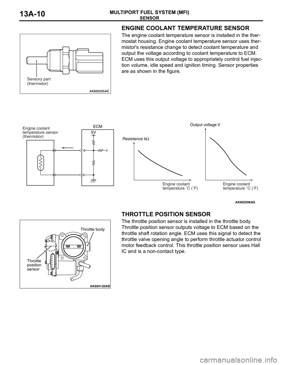
The engine coolant temperature sensor is installed in the ther-
mostat housing. Engine coolant temperature sensor uses ther-
mistor's resistance change to detect coolant temperature and
output the voltage according to coolant temperature to ECM.
ECM uses this output voltage to appropriately control fuel injec
-
tion volume, idle speed and ignition timing. Sensor properties
are as shown in the figure.
.
THROTTLE POSITION SENSOR
The throttle position sensor is installed in the throttle body.
Throttle position sensor outputs voltage to ECM based on the
throttle shaft rotation angle. ECM uses this signal to detect the
throttle valve opening angle to perform throttle actuator control
motor feedback control. This throttle position sensor uses Hall
IC and is a non-contact type.
.
AK602255AC
Sensory part
(thermistor)
AK602208
Engine coolant
temperature �C (�F)
AG
Output voltage V
5V Engine coolant
temperature sensor
(thermistor)
Engine coolant
temperature �C (�F) ECM
Resistance kΩ
AK604120AB
Throttle body
Throttle
position
sensor
Page 104 of 241
SENSOR
MULTIPORT FUEL SYSTEM (MFI)13A-11
STRUCTURE AND SYSTEM
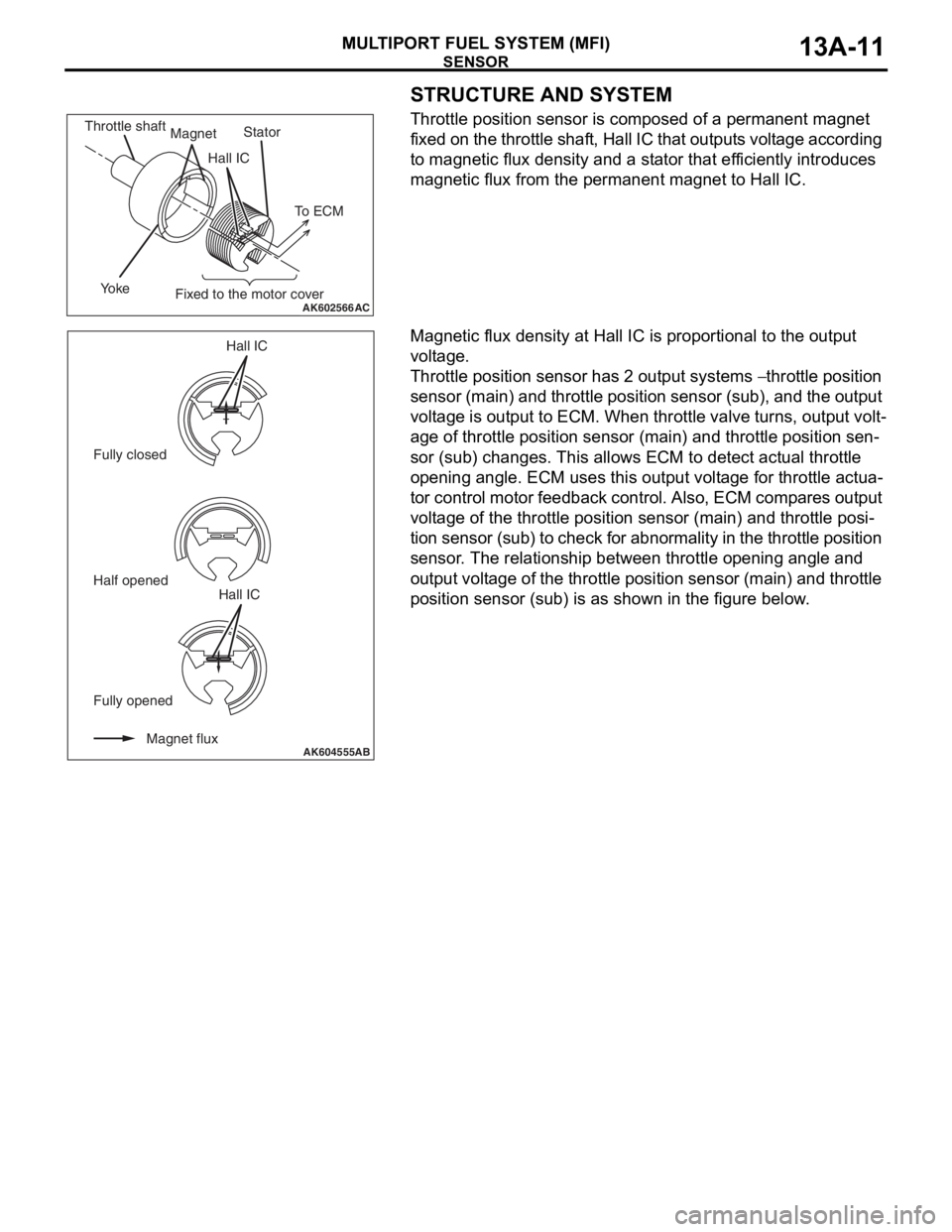
Throttle position sensor is composed of a permanent magnet
fixed on the throttle shaft, Hall IC that outputs voltage according
to magnetic flux density and a stator that efficiently introduces
magnetic flux from the permanent magnet to Hall IC.
Magnetic flux density at Hall IC is proportional to the output
voltage.
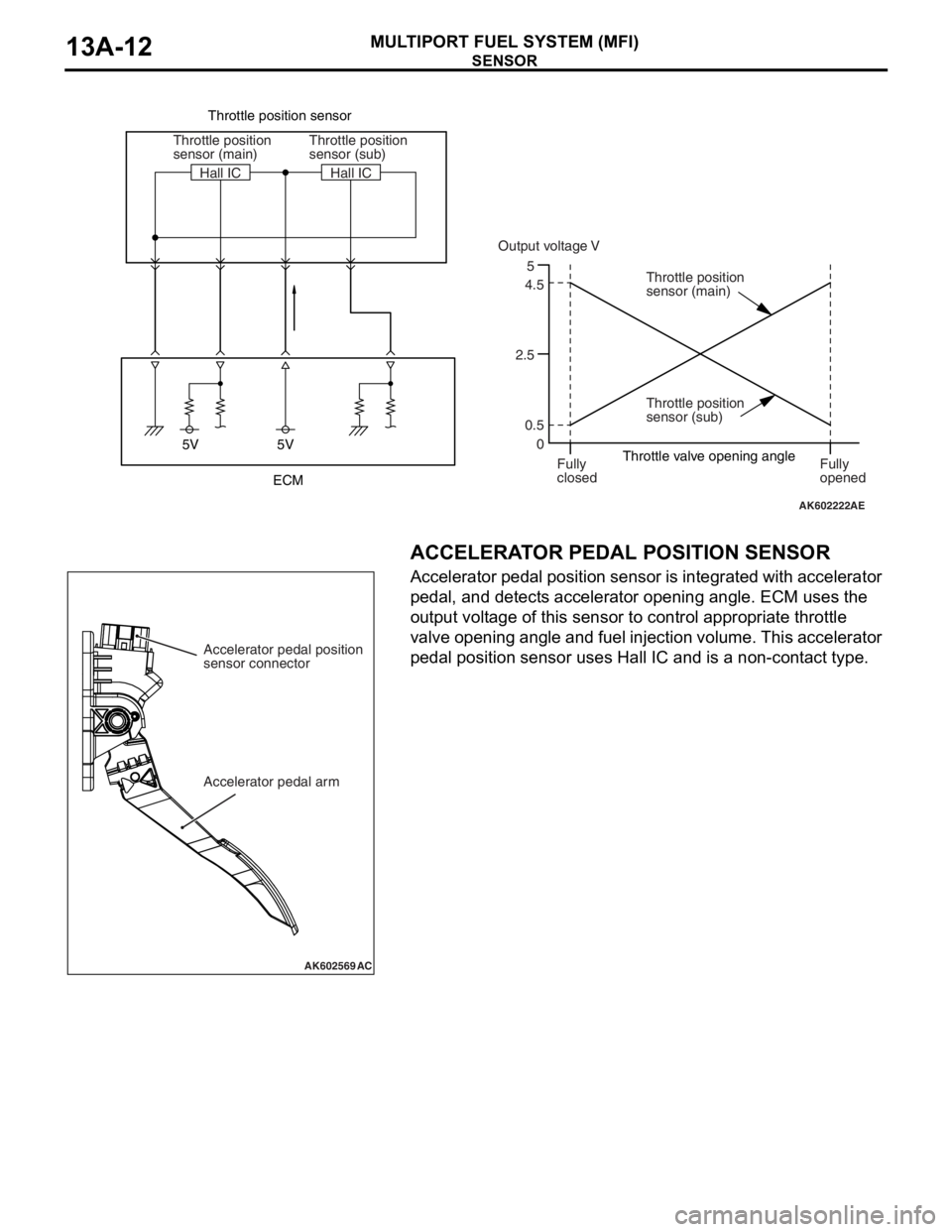
Throttle position sensor has 2 output systems − throttle position
sensor (main) and throttle position sensor (sub), and the output
voltage is output to ECM. When throttle valve turns, output volt
-
age of throttle position sensor (main) and throttle position sen-
sor (sub) changes. This allows ECM to detect actual throttle
opening angle. ECM uses this output voltage for throttle actua
-
tor control motor feedback control. Also, ECM compares output
voltage of the throttle position sensor (main) and throttle posi
-
tion sensor (sub) to check for abnormality in the throttle position
sensor. The relationship between throttle opening angle and
output voltage of the throttle position sensor (main) and throttle
position sensor (sub) is as shown in the figure below.
AK602566AC
Hall ICStator
Yo k e
Fixed to the motor cover Magnet Throttle shaft
To ECM
AK604555Magnet flux Fully opened Fully closedHall IC
Half opened
Hall ICAB
Page 105 of 241
SENSOR
MULTIPORT FUEL SYSTEM (MFI)13A-12
.
ACCELERATOR PEDAL POSITION SENSOR
Accelerator pedal position sensor is integrated with accelerator
pedal, and detects accelerator opening angle. ECM uses the
output voltage of this sensor to control appropriate throttle
valve opening angle and fuel injection volume. This accelerator
pedal position sensor uses Hall IC and is a non-contact type.
.
AK602222AE
5V 5VThrottle position sensor
Throttle valve opening angle
5
2.54.5
0.5
0 Throttle position
sensor (main)
Throttle position
sensor (sub) Throttle position
sensor (sub)
Throttle position
sensor (main) Hall IC
Fully
closedFully
opened Hall IC
Output voltage V
ECM
AK602569AC
Accelerator pedal position
sensor connector
Accelerator pedal arm
Page 106 of 241
SENSOR
MULTIPORT FUEL SYSTEM (MFI)13A-13
STRUCTURE AND SYSTEM
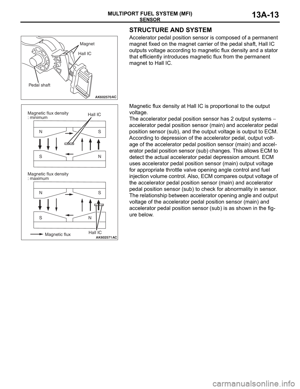
Accelerator pedal position sensor is composed of a permanent
magnet fixed on the magnet carrier of the pedal shaft, Hall IC
outputs voltage according to magnetic flux density and a stator
that efficiently introduces magnetic flux from the permanent
magnet to Hall IC.
Magnetic flux density at Hall IC is proportional to the output
voltage.
The accelerator pedal position sensor has 2 output systems −
accelerator pedal position sensor (main) and accelerator pedal
position sensor (sub), and the output voltage is output to ECM.
According to depression of the accelerator pedal, output volt
-
age of the accelerator pedal position sensor (main) and accel-
erator pedal position sensor (sub) changes. This allows ECM to
detect the actual accelerator pedal depression amount. ECM
uses accelerator pedal position sensor (main) output voltage
for appropriate throttle valve opening angle control and fuel
injection volume control. Also, ECM compares output voltage of
the accelerator pedal position sensor (main) and accelerator
pedal position sensor (sub) to check for abnormality in sensor.
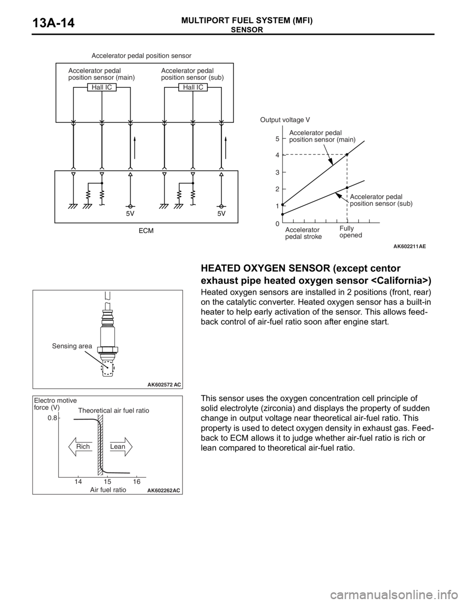
The relationship between accelerator opening angle and output
voltage of the accelerator pedal position sensor (main) and
accelerator pedal position sensor (sub) is as shown in the fig
-
ure below.
AK602570AC
Magnet
Pedal shaftHall IC
AK602571
S N
S N N S
N S
AC
Hall IC
Hall IC Magnetic flux density
: minimum
Magnetic flux density
: maximum
Magnetic flux
Page 107 of 241
SENSOR
MULTIPORT FUEL SYSTEM (MFI)13A-14
.
HEATED OXYGEN SENSOR (except centor
exhaust pipe heated oxygen sensor
Heated oxygen sensors are installed in 2 positions (front, rear)
on the catalytic converter. Heated oxygen sensor has a built-in
heater to help early activation of the sensor. This allows feed
-
back control of air-fuel ratio soon after engine start.
.
This sensor uses the oxygen concentration cell principle of
solid electrolyte (zirconia) and displays the property of sudden
change in output voltage near theoretical air-fuel ratio. This
property is used to detect oxygen density in exhaust gas. Feed
-
back to ECM allows it to judge whether air-fuel ratio is rich or
lean compared to theoretical air-fuel ratio.
AK602211
5V 5V
5
4
3
2
1
0
AE
Accelerator pedal position sensor
Accelerator pedal
position sensor (main)
Accelerator pedal
position sensor (main)
Accelerator
pedal stroke Accelerator pedal
position sensor (sub)
Accelerator pedal
position sensor (sub) Hall IC Hall IC
Fully
opened
Output voltage V
ECM
AK602572 AC
Sensing area
AK602262
AC
0.8
14 15 16Theoretical air fuel ratio Electro motive
force (V)
Rich Lean
Air fuel ratio
Page 108 of 241
SENSOR
MULTIPORT FUEL SYSTEM (MFI)13A-15
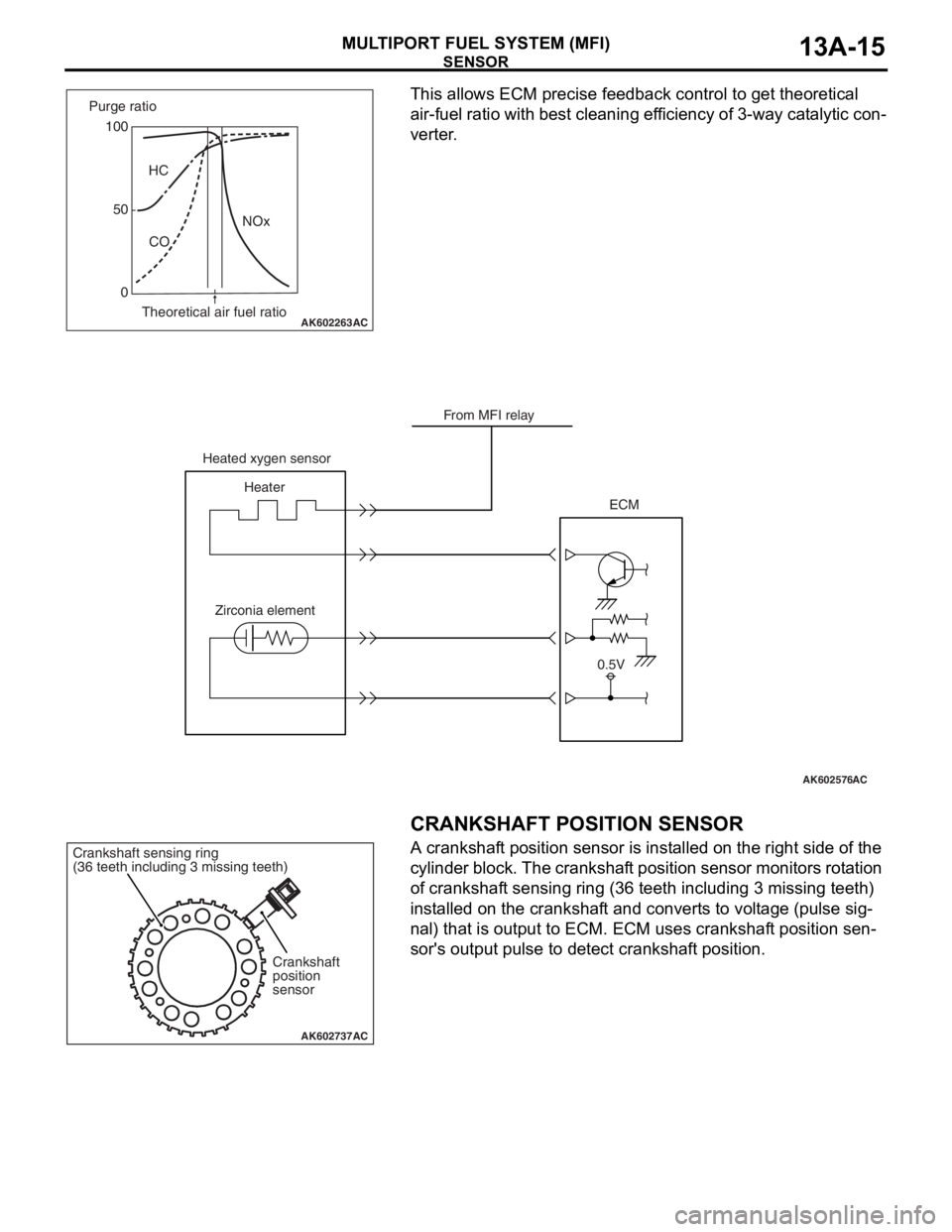
This allows ECM precise feedback control to get theoretical
air-fuel ratio with best cleaning efficiency of 3-way catalytic con
-
verter.
.
CRANKSHAFT POSITION SENSOR
A crankshaft position sensor is installed on the right side of the
cylinder block. The crankshaft position sensor monitors rotation
of crankshaft sensing ring (36 teeth including 3 missing teeth)
installed on the crankshaft and converts to voltage (pulse sig
-
nal) that is output to ECM. ECM uses crankshaft position sen-
sor's output pulse to detect crankshaft position.
.
AK602263AC
100
0HC
CONOx 50 Purge ratio
Theoretical air fuel ratio
AK602576AC
From MFI relay
Heated xygen sensor
Heater
Zirconia elementECM
0.5V
AK602737AC
Crankshaft
position
sensor Crankshaft sensing ring
(36 teeth including 3 missing teeth)
Page 109 of 241
SENSOR
MULTIPORT FUEL SYSTEM (MFI)13A-16
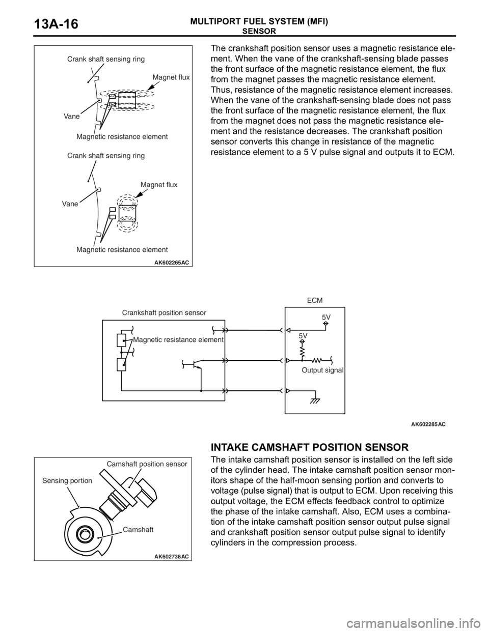
The crankshaft position sensor uses a magnetic resistance ele-
ment. When the vane of the crankshaft-sensing blade passes
the front surface of the magnetic resistance element, the flux
from the magnet passes the magnetic resistance element.
Thus, resistance of the magnetic resistance element increases.
When the vane of the crankshaft-sensing blade does not pass
the front surface of the magnetic resistance element, the flux
from the magnet does not pass the magnetic resistance ele
-
ment and the resistance decreases. The crankshaft position
sensor converts this change in resistance of the magnetic
resistance element to a 5 V pulse signal and outputs it to ECM.
.
INTAKE CAMSHAFT POSITION SENSOR
The intake camshaft position sensor is installed on the left side
of the cylinder head. The intake camshaft position sensor mon
-
itors shape of the half-moon sensing portion and converts to
voltage (pulse signal) that is output to ECM. Upon receiving this
output voltage, the ECM effects feedback control to optimize
the phase of the intake camshaft. Also, ECM uses a combina
-
tion of the intake camshaft position sensor output pulse signal
and crankshaft position sensor output pulse signal to identify
cylinders in the compression process.
AK602265AC
Crank shaft sensing ring
Crank shaft sensing ring Vane
VaneMagnetic resistance element
Magnetic resistance elementMagnet flux
Magnet flux
AK602285AC
5V5V Crankshaft position sensorECM
Output signal Magnetic resistance element
AK602738AC
Camshaft Sensing portionCamshaft position sensor
Page 110 of 241
SENSOR
MULTIPORT FUEL SYSTEM (MFI)13A-17
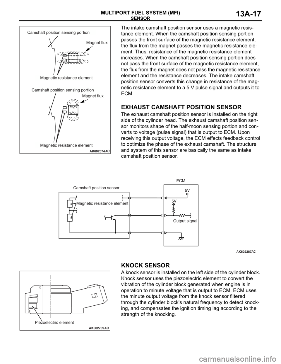
The intake camshaft position sensor uses a magnetic resis-
tance element. When the camshaft position sensing portion
passes the front surface of the magnetic resistance element,
the flux from the magnet passes the magnetic resistance ele
-
ment. Thus, resistance of the magnetic resistance element
increases. When the camshaft position sensing portion does
not pass the front surface of the magnetic resistance element,
the flux from the magnet does not pass the magnetic resistance
element and the resistance decreases. The intake camshaft
position sensor converts this change in resistance of the mag
-
netic resistance element to a 5 V pulse signal and outputs it to
ECM
.
EXHAUST CAMSHAFT POSITION SENSOR
The exhaust camshaft position sensor is installed on the right
side of the cylinder head. The exhaust camshaft position sen
-
sor monitors shape of the half-moon sensing portion and con-
verts to voltage (pulse signal) that is output to ECM. Upon
receiving this output voltage, the ECM effects feedback control
to optimize the phase of the exhaust camshaft. The structure
and system of this sensor are basically the same as intake
camshaft position sensor.
.
.
KNOCK SENSOR
A knock sensor is installed on the left side of the cylinder block.
Knock sensor uses the piezoelectric element to convert the
vibration of the cylinder block generated when engine is in
operation to minute voltage that is output to ECM. ECM uses
the minute output voltage from the knock sensor filtered
through the cylinder block's natural frequency to detect knock
-
ing, and compensates the ignition timing lag according to the
strength of the knocking.
AK602574AC
Camshaft position sensing portion
Camshaft position sensing portionMagnetic resistance element
Magnetic resistance elementMagnet flux
Magnet flux
AK602287
5V5V Camshaft position sensorECM
Output signal Magnetic resistance element
AC
AK602739
Piezoelectric element
AC