MITSUBISHI LANCER EVOLUTION X 2008 Workshop Manual
Manufacturer: MITSUBISHI, Model Year: 2008, Model line: LANCER EVOLUTION X, Model: MITSUBISHI LANCER EVOLUTION X 2008Pages: 241, PDF Size: 8.26 MB
Page 131 of 241
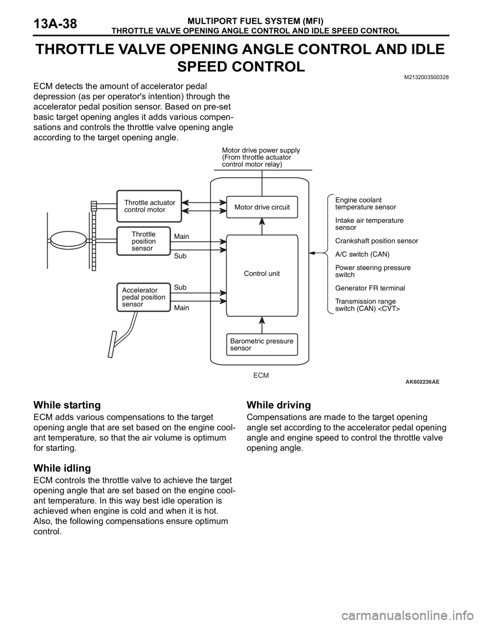
THROTTLE VALVE OPENING ANGLE CONTROL AND IDLE SPEED CONTROL
MULTIPORT FUEL SYSTEM (MFI)13A-38
THROTTLE VALVE OPENING ANGLE CONTROL AND IDLE
SPEED CONTROL
M2132003500328
ECM detects the amount of accelerator pedal
depression (as per operator's intention) through the
accelerator pedal position sensor. Based on pre-set
basic target opening angles it adds various compen
-
sations and controls the throttle valve opening angle
according to the target opening angle.
While starting
ECM adds various compensations to the target
opening angle that are set based on the engine cool
-
ant temperature, so that the air volume is optimum
for starting.
While idling
ECM controls the throttle valve to achieve the target
opening angle that are set based on the engine cool
-
ant temperature. In this way best idle operation is
achieved when engine is cold and when it is hot.
Also, the following compensations ensure optimum
control.
While driving
Compensations are made to the target opening
angle set according to the accelerator pedal opening
angle and engine speed to control the throttle valve
opening angle.
AK602236AE
Throttle
position
sensorMain
Main Sub
SubMotor drive circuit
A/C switch (CAN) Engine coolant
temperature sensor
Intake air temperature
sensor
Crankshaft position sensor
Power steering pressure
switch
Generator FR terminal
Transmission range
switch (CAN)
(From throttle actuator
control motor relay)
Throttle actuator
control motor
Control unit
Barometric pressure
sensor Accelerator
pedal position
sensor
ECM
Page 132 of 241

THROTTLE VALVE OPENING ANGLE CONTROL AND IDLE SPEED CONTROL
MULTIPORT FUEL SYSTEM (MFI)13A-39
List of main compensations for throttle valve opening angle and idle speed control
Initialize control
After ignition switch turns OFF, ECM drives the throt-
tle valve from fully closed position to fully open posi-
tion and records the fully closed/open studied value
of the throttle position sensor (main and sub) output
signals. The recorded studied values are used as
studied value compensation for compensating basic
target opening angle when the engine is started next.
CompensationsContent
Stable idle compensation (immediately after start)In order to stabilize idle speed immediately after
start, target opening angle is kept big and then
gradually reduced. Compensation values are set
based on the engine coolant temperature.
Rotation speed feedback compensation (while
idling)In case there is a difference between the target idle
speed and actual engine speed, ECM
compensates the throttle valve opening angle
based on that difference.
Atmospheric pressure compensationAt high altitudes atmospheric pressure is less and
the intake air density is low. So, the target opening
angle is compensated based on atmospheric
pressure.
Engine coolant temperature compensationCompensation is made according to the engine
coolant temperature. The lower the engine coolant
temperature the greater the throttle valve opening
angle.
Electric load compensationThrottle valve opening angle is compensated
according to electric load. The greater the electric
load, the greater the throttle valve opening angle.
Compensation when shift is in D range
to some other range, throttle valve opening angle is
increased to prevent reduction in engine speed.
Compensation when A/C is functioningThrottle valve opening angle is compensated
according to functioning of A/C compressor. While
A/C compressor is being driven, the throttle valve
opening angle is increased.
Power steering fluid pressure compensationThrottle valve opening angle is compensated
according to power steering functioning. When
power steering oil pressure rises and power
steering pressure switch is ON, the throttle valve
opening angle is increased.
Page 133 of 241
MIVEC (Mitsubishi Innovative Valve Timing Electronic Control System)
MULTIPORT FUEL SYSTEM (MFI)13A-40
MIVEC (Mitsubishi Innovative Valve Timing Electronic
Control System)
M2132023500212
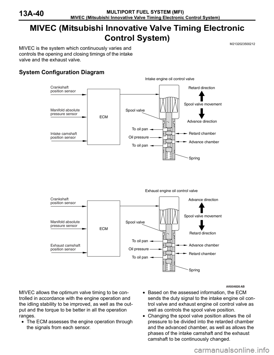
MIVEC is the system which continuously varies and
controls the opening and closing timings of the intake
valve and the exhaust valve.
System Configuration Diagram
MIVEC allows the optimum valve timing to be con-
trolled in accordance with the engine operation and
the idling stability to be improved, as well as the out
-
put and the torque to be better in all the operation
ranges.
•The ECM assesses the engine operation through
the signals from each sensor.
•Based on the assessed information, the ECM
sends the duty signal to the intake engine oil con
-
trol valve and exhaust engine oil control valve as
well as controls the spool valve position.
•Changing the spool valve position allows the oil
pressure to be divided into the retarded chamber
and the advanced chamber, as well as allows the
phases of the intake camshaft and the exhaust
camshaft to be continuously changed.
AK604826AB
Crankshaft
position sensor
Manifold absolute
pressure sensor
Intake camshaft
position sensorECMSpool valve
To oil pan
To oil pan Oil pressureAdvance direction Spool valve movementRetard direction Intake engine oil control valve
Retard chamber
Advance chamber
Spring
Crankshaft
position sensor
Manifold absolute
pressure sensor
Exhaust camshaft
position sensorECMSpool valve
To oil pan
To oil pan Oil pressureRetard direction Spool valve movementAdvance direction Exhaust engine oil control valve
Advance chamber
Retard chamber
Spring
Page 134 of 241
MIVEC (Mitsubishi Innovative Valve Timing Electronic Control System)
MULTIPORT FUEL SYSTEM (MFI)13A-41
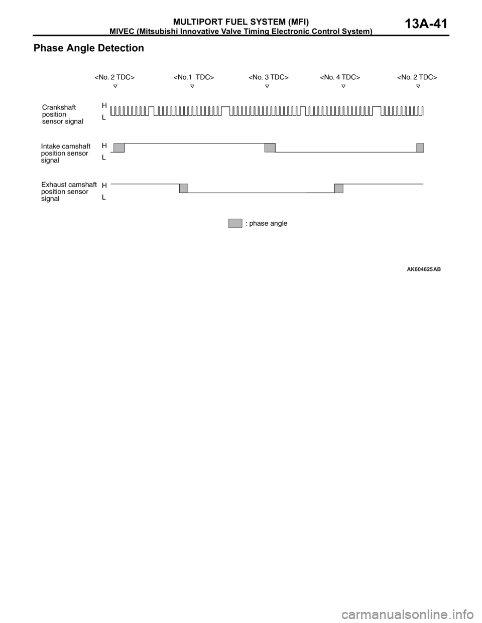
Phase Angle Detection
AK604625
H
L H
L
H
L
AB
Crankshaft
position
sensor signal
Intake camshaft
position sensor
signal
Exhaust camshaft
position sensor
signal
: phase angle
Page 135 of 241
MIVEC (Mitsubishi Innovative Valve Timing Electronic Control System)
MULTIPORT FUEL SYSTEM (MFI)13A-42
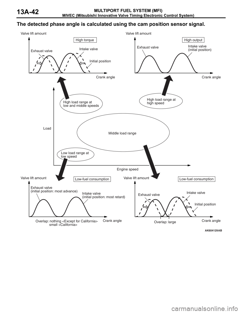
The detected phase angle is calculated using the cam position sensor signal.
AK604129AB
Overlap: nothing
small
(initial position)
Exhaust valve
(initial position: most advance)
Intake valve
(initial position: most retard)Exhaust valveIntake valve
Initial position
Overlap: large Initial position
Crank angle Crank angle
Crank angle Crank angle Valve lift amount Valve lift amountValve lift amount Valve lift amount
LoadHigh output High torque
Middle load range
Low load range at
low speedHigh load range at
low and middle speedsHigh load range at
high speed
Engine speed
Low-fuel consumptionLow-fuel consumption
Page 136 of 241
MIVEC (Mitsubishi Innovative Valve Timing Electronic Control System)
MULTIPORT FUEL SYSTEM (MFI)13A-43
Operation conditionValve timingOperationEffectiveness
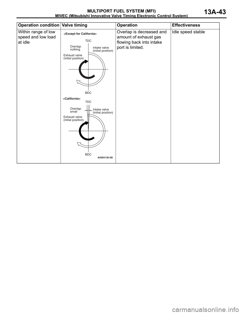
Within range of low
speed and low load
at idleOverlap is decreased and
amount of exhaust gas
flowing back into intake
port is limited.Idle speed stable
AK604130AB
TDC
BDC Exhaust valve
(initial position)Intake valve
(initial position) Overlap:
smallTDC
BDC Exhaust valve
(initial position)Intake valve
(initial position) Overlap:
nothing
Page 137 of 241
MIVEC (Mitsubishi Innovative Valve Timing Electronic Control System)
MULTIPORT FUEL SYSTEM (MFI)13A-44
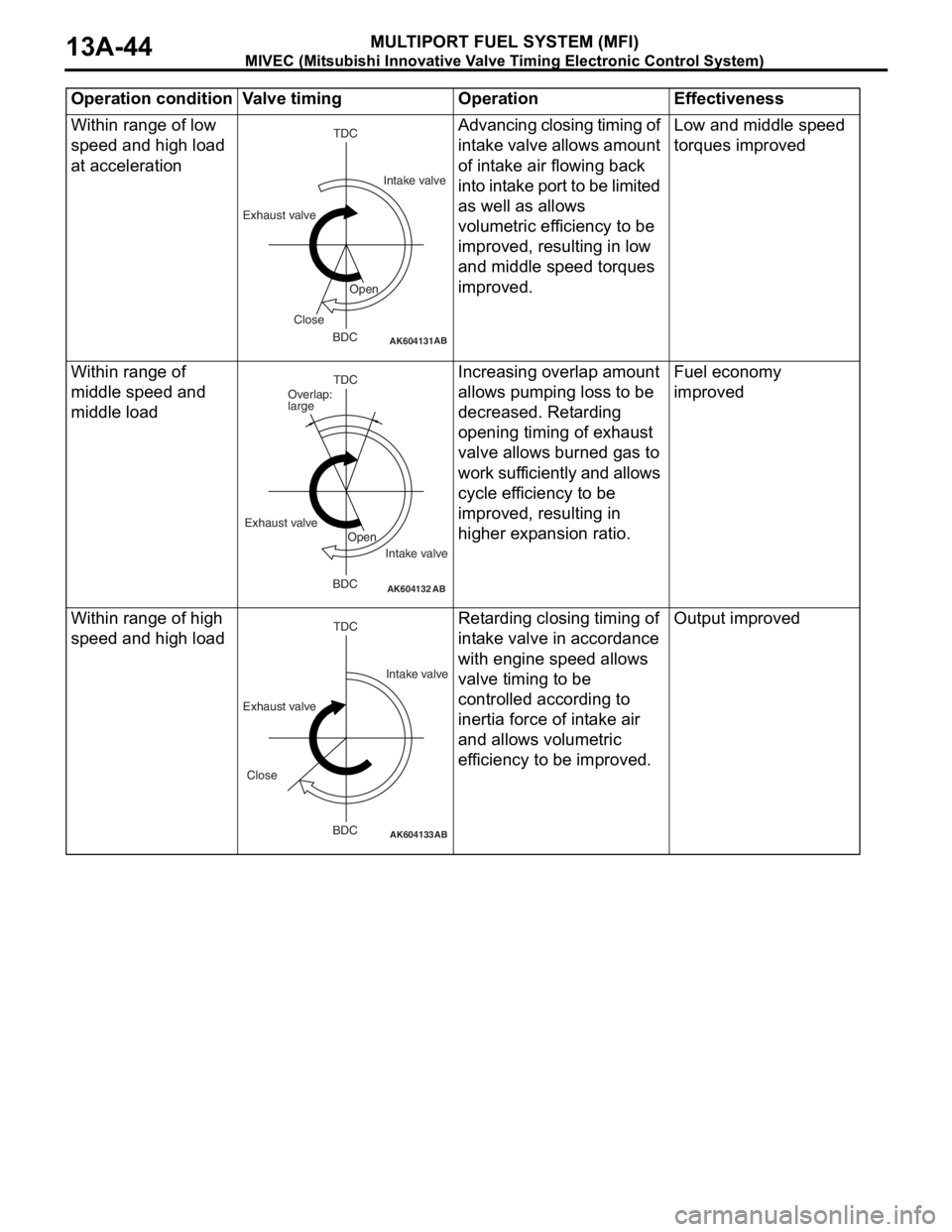
Within range of low
speed and high load
at accelerationAdvancing closing timing of
intake valve allows amount
of intake air flowing back
into intake port to be limited
as well as allows
volumetric efficiency to be
improved, resulting in low
and middle speed torques
improved.Low and middle speed
torques improved
Within range of
middle speed and
middle loadIncreasing overlap amount
allows pumping loss to be
decreased. Retarding
opening timing of exhaust
valve allows burned gas to
work sufficiently and allows
cycle efficiency to be
improved, resulting in
higher expansion ratio.Fuel economy
improved
Within range of high
speed and high loadRetarding closing timing of
intake valve in accordance
with engine speed allows
valve timing to be
controlled according to
inertia force of intake air
and allows volumetric
efficiency to be improved.Output improved
Operation condition Valve timing Operation Effectiveness
AK604131AB
TDC
BDC Exhaust valveIntake valve
Open
Close
AK604132AB
TDC
BDC Exhaust valve
Intake valve Overlap:
large
Open
AK604133
TDC
BDC
AB
Exhaust valveIntake valve
Close
Page 138 of 241
MULTIPORT FUEL INJECTION (MFI) RELAY CONTROL
MULTIPORT FUEL SYSTEM (MFI)13A-45
MULTIPORT FUEL INJECTION (MFI) RELAY CONTROLM2132006000173
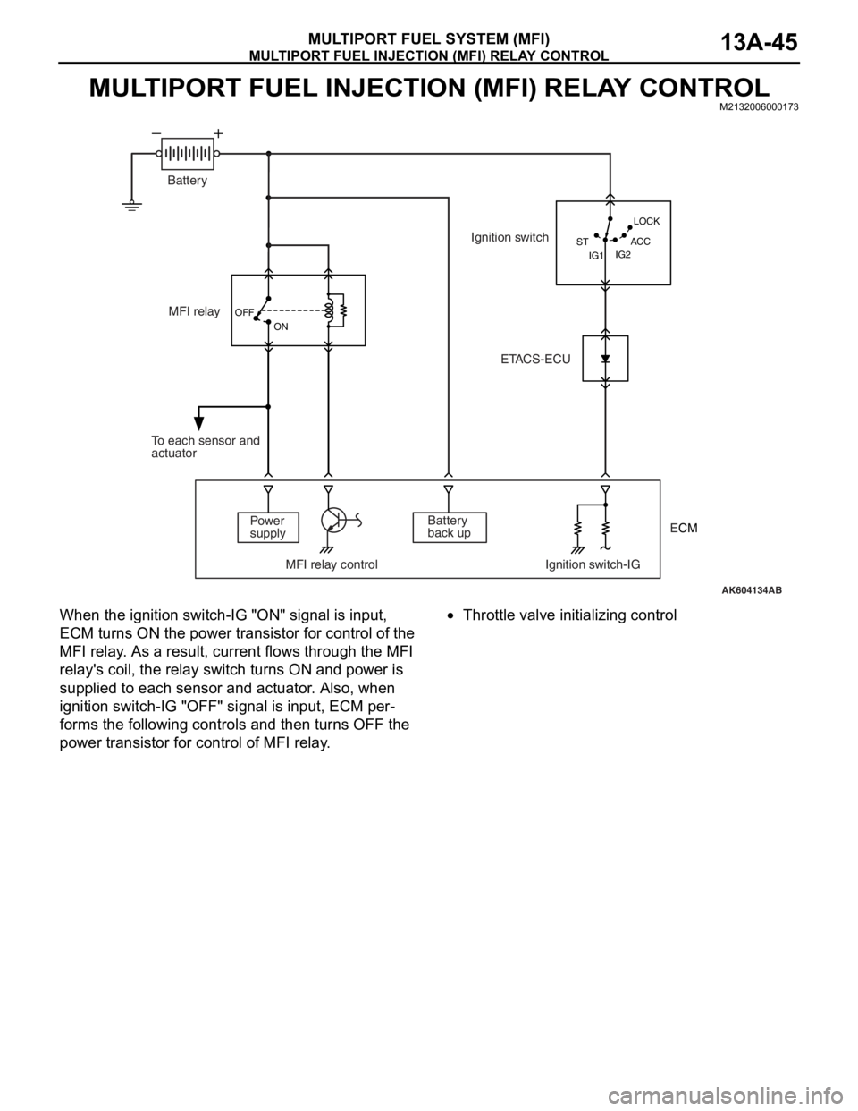
When the ignition switch-IG "ON" signal is input,
ECM turns ON the power transistor for control of the
MFI relay. As a result, current flows through the MFI
relay's coil, the relay switch turns ON and power is
supplied to each sensor and actuator. Also, when
ignition switch-IG "OFF" signal is input, ECM per
-
forms the following controls and then turns OFF the
power transistor for control of MFI relay.
•Throttle valve initializing control
AK604134AB OFF
ON
IG2 STLOCK
ACC
IG1
MFI relay
Power
supply
MFI relay control Ignition switch-IGBattery
back up To each sensor and
actuatorIgnition switch
ETACS-ECU Battery
ECM
Page 139 of 241
FUEL PUMP RELAY CONTROL
MULTIPORT FUEL SYSTEM (MFI)13A-46
FUEL PUMP RELAY CONTROLM2132006500208
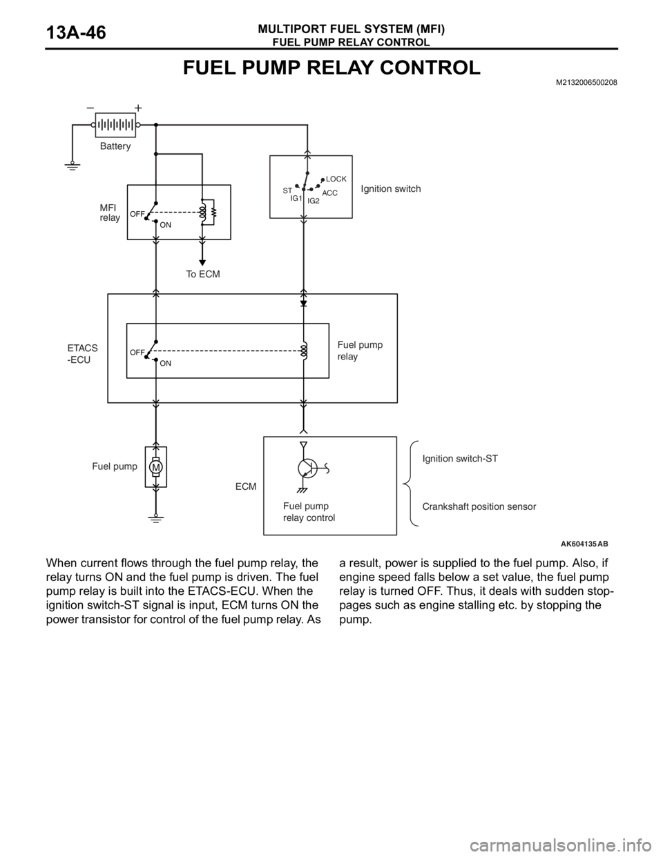
When current flows through the fuel pump relay, the
relay turns ON and the fuel pump is driven. The fuel
pump relay is built into the ETACS-ECU. When the
ignition switch-ST signal is input, ECM turns ON the
power transistor for control of the fuel pump relay. As a result, power is supplied to the fuel pump. Also, if
engine speed falls below a set value, the fuel pump
relay is turned OFF. Thus, it deals with sudden stop
-
pages such as engine stalling etc. by stopping the
pump.
AK604135
M
OFF
ON
OFF
ON
AB IG2 STLOCK
ACC
IG1
ETACS
-ECUMFI
relay
ECM Fuel pumpFuel pump
relay
Crankshaft position sensor Ignition switch
To ECM
Ignition switch-ST Battery
Fuel pump
relay control
Page 140 of 241
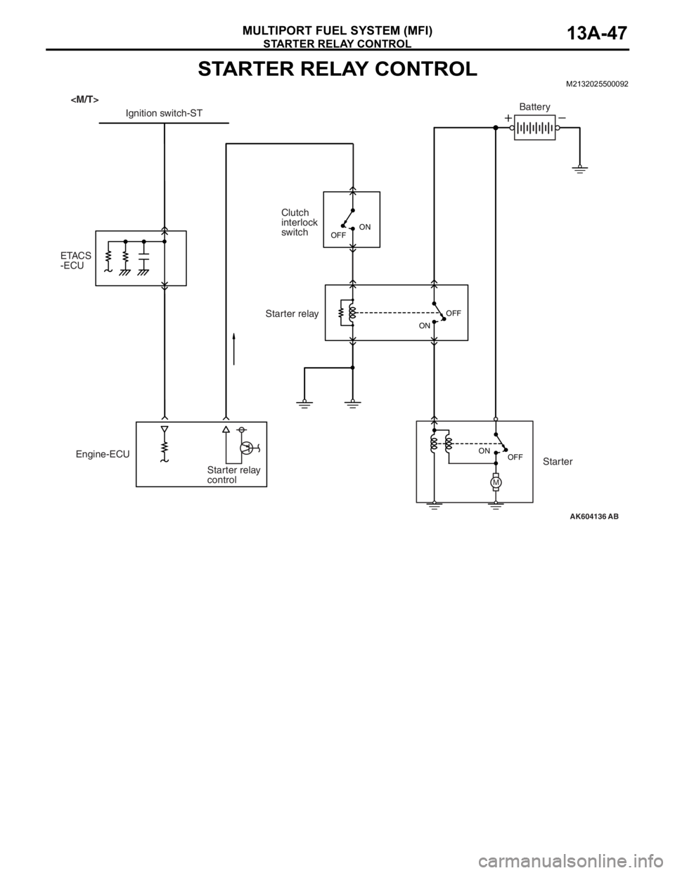
STARTER RELAY CONTROL
MULTIPORT FUEL SYSTEM (MFI)13A-47
STARTER RELAY CONTROLM2132025500092
AK604136
M
AB OFF ON OFF
ON
Engine-ECU
Starter relay
controlClutch
interlock
switch
ETACS
-ECUIgnition switch-STBattery
Starter relay
Starter
OFFON