MITSUBISHI LANCER EVOLUTION X 2008 Repair Manual
Manufacturer: MITSUBISHI, Model Year: 2008, Model line: LANCER EVOLUTION X, Model: MITSUBISHI LANCER EVOLUTION X 2008Pages: 241, PDF Size: 8.26 MB
Page 61 of 241
BASE ENGINE
ENGINE MECHANICAL11A-17
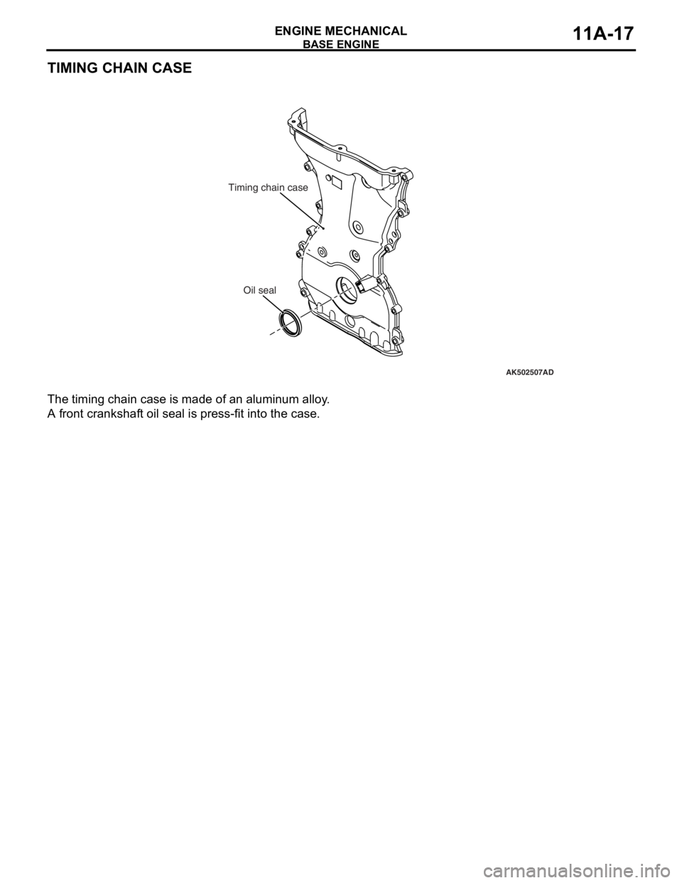
TIMING CHAIN CASE
The timing chain case is made of an aluminum alloy.
A front crankshaft oil seal is press-fit into the case.
AK502507
Oil seal
AD
Timing chain case
Page 62 of 241

NOTES
Page 63 of 241
17-1
GROUP 17
ENGINE AND
EMISSION
CONTROL
CONTENTS
ENGINE CONTROL . . . . . . . . . . . . . .17-2
GENERAL INFORMATION . . . . . . . . . . . . . 17-2
AUTO-CRUISE CONTROL SYSTEM17-2
GENERAL INFORMATION . . . . . . . . . . . . . 17-2
CONSTRUCTION AND OPERATION . . . . 17-5
EMISSION CONTROL . . . . . . . . . . . .17-8
GENERAL DESCRIPTION . . . . . . . . . . . . . 17-8
CRANKCASE VENTILATION SYSTEM . . . 17-10
EVAPORATIVE EMISSION CONTROL
SYSTEM . . . . . . . . . . . . . . . . . . . . . . . . . . . 17-11
EXHAUST GAS RECIRCULATION (EGR)
SYSTEM
EMISSION REDUCTION SYSTEMS. . . . . . 17-14
Page 64 of 241
ENGINE CONTROL
ENGINE AND EMISSION CONTROL17-2
ENGINE CONTROL
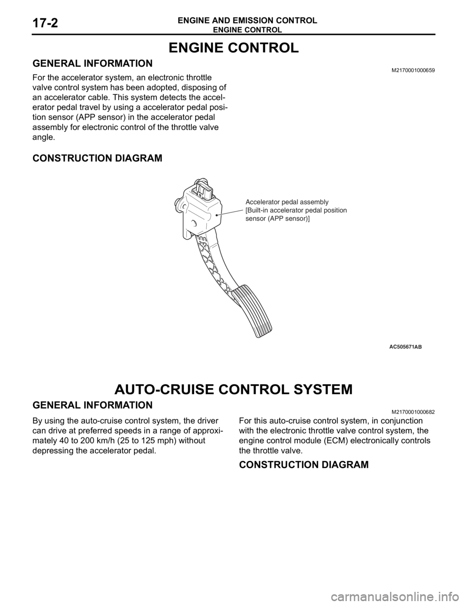
GENERAL INFORMATIONM2170001000659
For the accelerator system, an electronic throttle
valve control system has been adopted, disposing of
an accelerator cable. This system detects the accel
-
erator pedal travel by using a accelerator pedal posi-
tion sensor (APP sensor) in the accelerator pedal
assembly for electronic control of the throttle valve
angle.
CONSTRUCTION DIAGRAM
AUTO-CRUISE CONTROL SYSTEM
GENERAL INFORMATIONM2170001000682
By using the auto-cruise control system, the driver
can drive at preferred speeds in a range of approxi
-
mately 40 to 200 km/h (25 to 125 mph) without
depressing the accelerator pedal.
For this auto-cruise control system, in conjunction
with the electronic throttle valve control system, the
engine control module (ECM) electronically controls
the throttle valve.
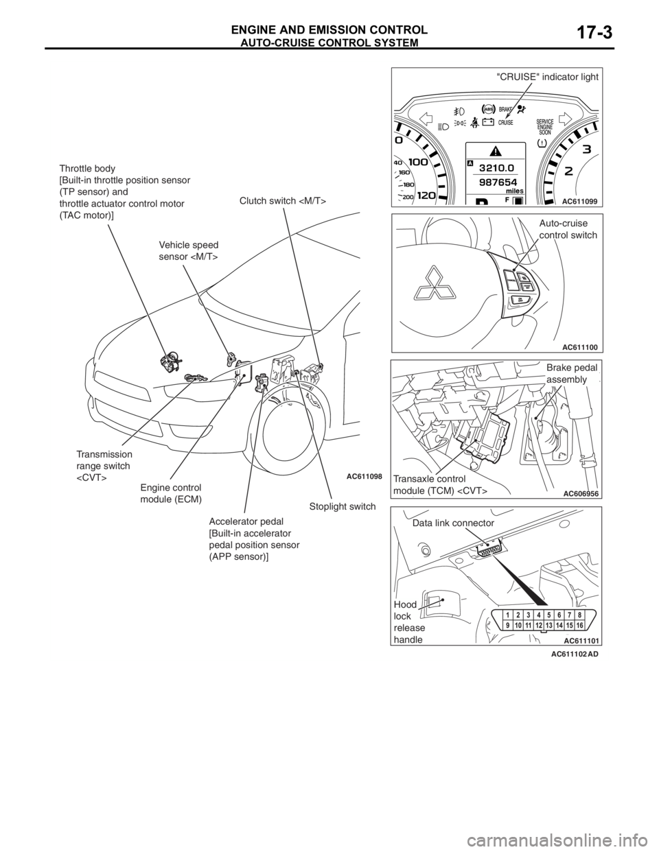
CONSTRUCTION DIAGRAM
AC505671AB
Accelerator pedal assembly
[Built-in accelerator pedal position
sensor (APP sensor)]
Page 65 of 241
AUTO-CRUISE CONTROL SYSTEM
ENGINE AND EMISSION CONTROL17-3
AC611102 AC611098
AC611099
AC611100
AC606956
AC611101
Auto-cruise
control switch
Data link connector
Hood
lock
release
handle
AD
Clutch switch
Stoplight switch
Accelerator pedal
[Built-in accelerator
pedal position sensor
(APP sensor)] Engine control
module (ECM)"CRUISE" indicator light
Transaxle control
module (TCM)
Brake pedal
assembly
Throttle body
[Built-in throttle position sensor
(TP sensor) and
throttle actuator control motor
(TAC motor)]
Transmission
range switch
Vehicle speed
sensor
Page 66 of 241

AUTO-CRUISE CONTROL SYSTEM
ENGINE AND EMISSION CONTROL17-4
COMPONENTS AND FUNCTIONS
ComponentFunction
Accelerator pedal position sensor (APP sensor)Informs the ECM of the accelerator pedal
depression.
Auto-cruise control switch"ON/OFF" switchPower switch for auto-cruise control system.
"ACC/RES" switchVehicle speed is set with the "ACC/RES" switch and
"COAST/SET" switch.
"COAST/SET" switch
"CANCEL" switchCancels the cruise speed setting.
Cancel systemClutch switch
the clutch operation, the clutch pedal status is
detected.
Stoplight switch•Because the constant speed driving is canceled
by the brake operation, it detects the brake pedal
status.
•As for the stoplight switch, two built-in switches,
the stoplight switch which is also used for the
stoplight illumination and the brake switch which
is used exclusively for the auto-cruise control, are
integrated, and thus the reliability is enhanced.
Transmission range
switch
the selector lever operation, it detects the "N"
position.
"CRUISE" indicator lightThe light is included in the combination meter and
illuminates when the "ON/OFF" switch is pressed
(auto-cruise control system: ON).
Data link connectorIf the M.U.T.-III scan tool is connected, the input
check code from the ECM can be read.
Engine control module (ECM)•Based on the input signal from each sensor and
switch, it outputs the throttle opening instruction
signal to the TAC motor.
•Based on the input signal from each sensor and
switch, it outputs the transaxle control signal to
the TCM
•Based on the vehicle speed signal from the
vehicle speed sensor, it calculates the vehicle
speed
•Based on the secondary pulley speed sensor
signal from the TCM, it calculates the vehicle
speed
•Based on the selector lever "N" position signal of
the transmission range switch from the ECM, it
cancels constant speed driving.
•Outputs the ON/OFF signals of "CRUISE"
indicator light and auto-cruise control system.
•The diagnostic trouble code signal is sent to the
"CRUISE" indicator light.
•The input check code is sent to the data link
connector.
Throttle actuator control motor (TAC motor)The throttle valve opens and closes in response to
the throttle angle signal from the ECM.
Page 67 of 241
AUTO-CRUISE CONTROL SYSTEM
ENGINE AND EMISSION CONTROL17-5
CONSTRUCTION AND OPERATIONM2170002000232
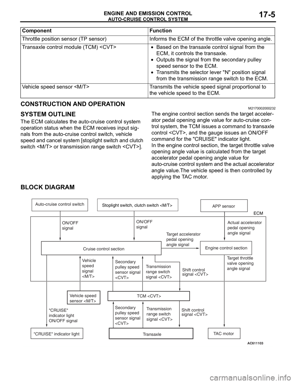
SYSTEM OUTLINE
The ECM calculates the auto-cruise control system
operation status when the ECM receives input sig
-
nals from the auto-cruise control switch, vehicle
speed and cancel system [stoplight switch and clutch
switch
-
ator pedal opening angle value for auto-cruise con-
trol system, the TCM issues a command to transaxle
control
command for the "CRUISE" indicator light.
In the engine control section, the target throttle valve
opening angle value is calculated from the target
accelerator pedal opening angle value for
auto-cruise control system and the actual accelerator
angle value.The vehicle speed is then controlled by
applying the TAC motor.
BLOCK DIAGRAM
Throttle position sensor (TP sensor)Informs the ECM of the throttle valve opening angle.
Transaxle control module (TCM)
ECM, it controls the transaxle.
•Outputs the signal from the secondary pulley
speed sensor to the ECM.
•Transmits the selector lever "N" position signal
from the transmission range switch to the ECM.
Vehicle speed sensor
the vehicle speed to the ECM.
Component Function
TAC motor Target accelerator
pedal opening
angle signal
Engine control section
Cruise control section"CRUISE" indicator light
AC611103
Actual accelerator
pedal opening
angle signal
Shift control
signal
Target throttle
valve opening
angle signal
Auto-cruise control switch
ECM
Stoplight switch, clutch switch
TCM
"CRUISE"
indicator light
ON/OFF signal
APP sensor
Transmission
range switch
signal
signal
TransaxleTransmission
range switch
signal
Secondary
pulley speed
sensor signal
signalON/OFF
signal
Vehicle speed
sensor
Vehicle
speed
signal
pulley speed
sensor signal
Page 68 of 241

AUTO-CRUISE CONTROL SYSTEM
ENGINE AND EMISSION CONTROL17-6
SYSTEM FUNCTIONS
.
SET FUNCTION
1. During driving with the vehicle speed range from
approximately 40 to 200 km/h (25 to 125 mph),
press and release the "COAST/SET" switch.
2. The vehicle speed when the "COAST/SET" switch
is released is memorized. Thereafter, the constant
speed driving is performed at that vehicle speed.
3. When the "COAST/SET" switch is operated
during the driving with the vehicle speed of
approximately 200 km/h (125 mph) or more, the
constant speed driving will not be performed.
.
COAST FUNCTION
1. When the "COAST/SET" switch is continuously
pressed for 0.5 seconds or longer during constant
speed driving, the throttle valve becomes fully
closed while the switch is pressed, and the
vehicle is decelerated.
2. When the "COAST/SET" switch is released, the
vehicle speed at that time is now memorized.
Thereafter, the constant speed driving is
performed at that vehicle speed.
3. Also when the "COAST/SET" switch is pressed
for less than 0.5 second, the vehicle is
decelerated 1.6 km/h (1 mph) from the vehicle
speed of constant speed driving, and the
decelerated vehicle speed is now memorized.
Thereafter, the constant speed driving is
performed at that vehicle speed.
4. When the "COAST/SET" switch is continuously
pressed and the vehicle speed is decelerated to
approximately 40 km/h (25 mph) or less, the set
function and coast function are cancelled, and the
constant speed driving is cancelled.
.
RESUME FUNCTION
1. When the "CANCEL" switch is pressed or the
brake pedal is depressed during the constant
speed driving, it cancels the constant speed
driving.
2. Subsequently, when the "ACC/RES" switch is
pressed during driving with the vehicle speed of
approximately 40 km/h (25 mph) or more, the
constant speed driving is performed with the
vehicle speed memorized at the last cancellation
of constant speed driving.
.
ACCEL FUNCTION
1. When the "ACC/RES" switch is continuously
pressed for 0.5 second or more during constant
driving, it accelerates the vehicle with specified
acceleration while the switch is pressed.
2. Then, when the "ACC/RES" switch is released,
the vehicle speed at that time is now memorized.
Thereafter, the constant speed driving is
performed at that vehicle speed.
3. Also, when the "ACC/RES" switch is pressed for
less than 0.5 second, the vehicle is accelerated
1.6 km/h (1 mph) from the vehicle speed of
constant speed driving, and the accelerated
vehicle speed is now memorized. Thereafter, the
constant speed driving is performed at that
vehicle speed.
4. It is possible to keep pressing the "ACC/RES"
switch until the vehicle speed is accelerated to
approximately 200 km/h (125 mph) or above.
However, after the "ACC/RES" switch is released,
the vehicle speed of approximately 200 km/h (125
mph) becomes the newly memorized vehicle
speed. Thereafter, the constant speed driving is
performed at that speed.
.
CANCEL FUNCTION
When any of the following conditions are satisfied,
the constant speed driving will be cancelled.
•The auto-cruise control system is stopped by the
pressing the "ON OFF" switch.
•The "CANCEL" switch is pressed.
•The brake pedal is depressed.
•The clutch pedal is depressed
•The selector lever is shifted to the "N" position
•The vehicle speed becomes approximately 40
km/h (25 mph) or less.
•The vehicle speed is reduced 15 km/h (9 mph) or
more from the speed at which the constant speed
driving was started.
•An abnormality occurs in the vehicle speed sig-
nal.
•The engine coolant temperature becomes abnor-
mally high.
•An abnormality occurs to the ECM.
•An abnormality occurs to the TCM
•An abnormality occurs to the CAN communica-
tion.
.
Page 69 of 241

AUTO-CRUISE CONTROL SYSTEM
ENGINE AND EMISSION CONTROL17-7
FAIL-SAFE FUNCTION
When any of the following conditions are satisfied,
the auto-cruise control system function is stopped
until the system returns to normal. Also, when any of
the conditions are satisfied during the constant
speed driving, the constant speed driving is can
-
celled immediately.
•An abnormality occurs to the auto-cruise control
switch.
•An abnormality occurs to the stoplight switch.
When any of the following conditions are satisfied,
stop the vehicle once and turn the ignition switch to
"LOCK" (OFF). Otherwise, even when the system
returns to normal, the auto-cruise control system
function will continue to be stopped. Also, when any
of the conditions are satisfied during the constant
speed driving, the constant speed driving is can
-
celled immediately.
•ECM abnormality
•TP sensor abnormality
•APP sensor abnormality
.
DIAGNOSIS FUNCTION
•The diagnostic trouble code check is possible
with the "CRUISE" indicator light.
•To facilitate the system check, check the service
data output with the M.U.T.-III.
NOTE: For diagnostic items, service data output
items, and check method, refer to the Service Man
-
ual.
Page 70 of 241
EMISSION CONTROL
ENGINE AND EMISSION CONTROL17-8
EMISSION CONTROL
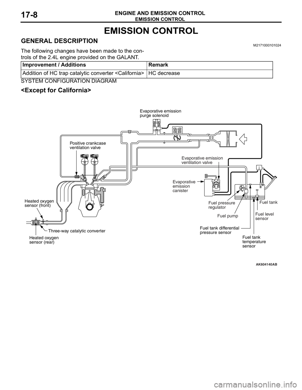
GENERAL DESCRIPTIONM2171000101024
The following changes have been made to the con-
trols of the 2.4L engine provided on the GALANT.
SYSTEM CONFIGURATION DIAGRAM
Improvement / AdditionsRemark
Addition of HC trap catalytic converter
AK604140
Positive crankcase
ventilation valve
Fuel pressure
regulator Evaporative emission
purge solenoid
Evaporative
emission
canisterEvaporative emission
ventilation valve
Fuel level
sensor
Fuel tank differential
pressure sensor
Fuel tank
temperature
sensor Fuel pump
Three-way catalytic converter Heated oxygen
sensor (front)
Heated oxygen
sensor (rear)Fuel tank
AB