MITSUBISHI LANCER EVOLUTION X 2008 Workshop Manual
Manufacturer: MITSUBISHI, Model Year: 2008, Model line: LANCER EVOLUTION X, Model: MITSUBISHI LANCER EVOLUTION X 2008Pages: 241, PDF Size: 8.26 MB
Page 171 of 241
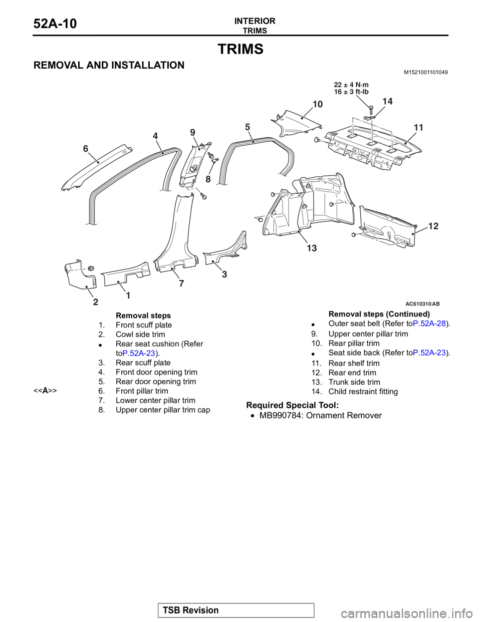
TRIMS
TSB Revision
INTERIOR52A-10
TRIMS
REMOVAL AND INSTALLATIONM1521001101049
Required Special Tool:
•MB990784: Ornament Remover
AC610310
45
1 3
6
2 79
11
12
10
13
AB
8
14
22 ± 4 N·m
16 ± 3 ft-lb
Removal steps
1.Front scuff plate
2.Cowl side trim
•Rear seat cushion (Refer
to
P.52A-23).
3.Rear scuff plate
4.Front door opening trim
5.Rear door opening trim
<>6.Front pillar trim
7.Lower center pillar trim
8.Upper center p illar trim cap
•Outer seat belt (Refer toP.52A-28).
9.Upper center pillar trim
10.Rear pillar trim
•Seat side back (Refer toP.52A-23).
11 .Rear shelf trim
12.Rear end trim
13.Trunk side trim
14.Child restraint fitting
Removal steps (Continued)
Page 172 of 241
TRIMS
TSB Revision
INTERIOR52A-11
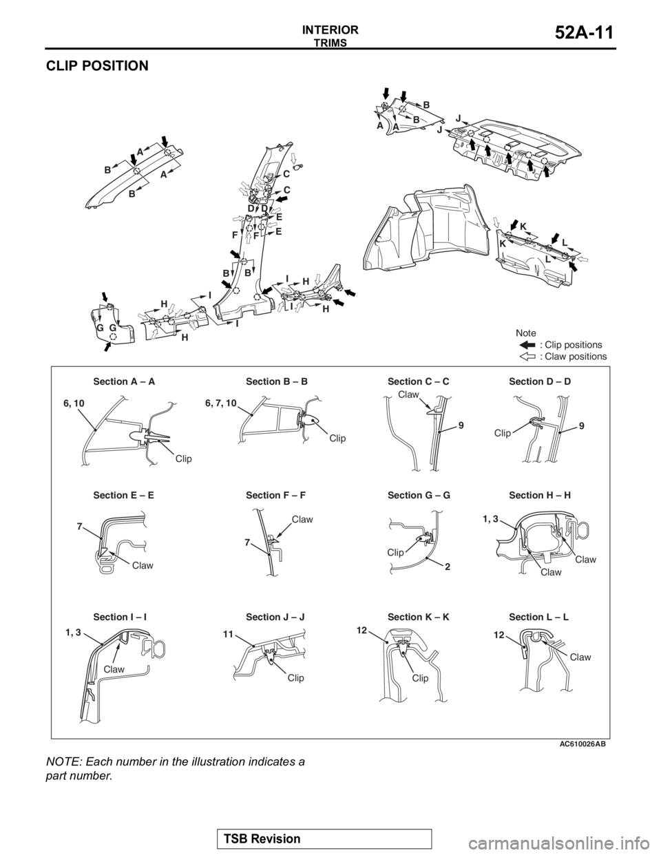
CLIP POSITION
NOTE: Each number in the illustration indicates a
part number.
AC610026AB
Note
: Clip positions
: Claw positions
Section A – A Section B – B Section C – C Section D – D
Section E – E Section F – F Section G – G Section H – H
Section I – I Section J – J Section K – K Section L – L Claw
Clip
Clip
Clip
Clip
Claw
Clip
Claw
Claw
Claw
Clip
Claw
Claw
A
B
B A
C
E
E
B DD
C A
B
J
J
KL
L
K
B
AB
F
F
G
G H
I
I I
H H
H
I
6, 10
6, 7, 10
99
7
7
1, 3
2
1212111, 3
Page 173 of 241
TRIMS
TSB Revision
INTERIOR52A-12
REMOVAL SERVICE POINT
.
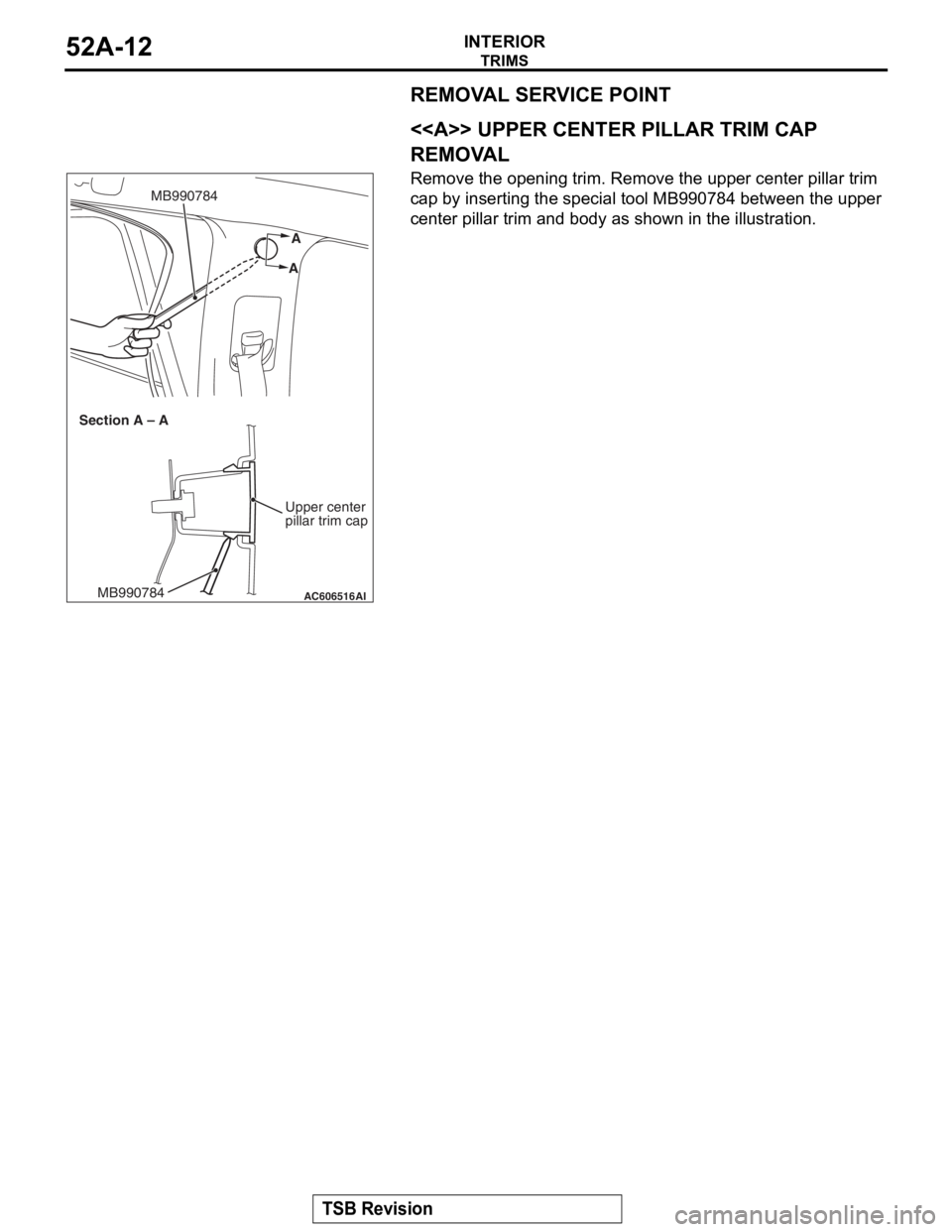
<> UPPER CENTER PILLAR TRIM CAP
REMOVAL
Remove the opening trim. Remove the upper center pillar trim
cap by inserting the special tool MB990784 between the upper
center pillar trim and body as shown in the illustration.
AC606516
A
A
MB990784
AIMB990784
Section A – A
Upper center
pillar trim cap
Page 174 of 241
DOOR TRIM
TSB Revision
INTERIOR52A-13
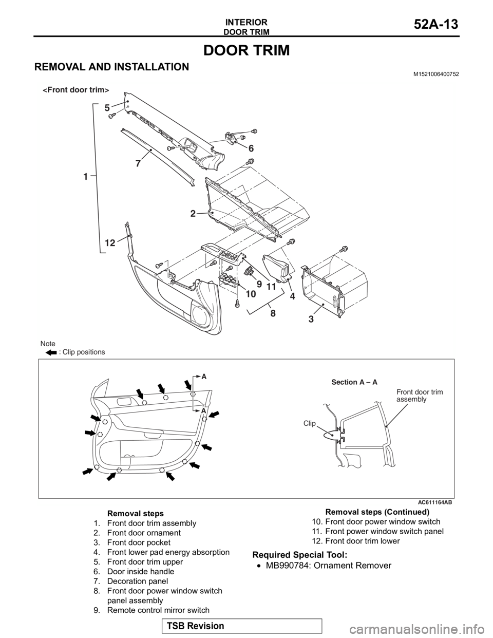
DOOR TRIM
REMOVAL AND INSTALLATIONM1521006400752
Required Special Tool:
•MB990784: Ornament Remover
AC611164
15
7
12 6
2
8
9
10 11
3
4
A
Section A – A
Note
: Clip positions
A
Clip
Front door trim
assembly
AB
Removal steps
1.Front door trim assembly
2.Front door ornament
3.Front door pocket
4.Front lower pad energy absorption
5.Front door trim upper
6.Door inside handle
7.Decoration panel
8.Front door power window switch
panel assembly
9.Remote control mirror switch
10.Front door power window switch
11 .Front power window switch panel
12.Front door trim lower
Removal steps (Continued)
Page 175 of 241
DOOR TRIM
TSB Revision
INTERIOR52A-14
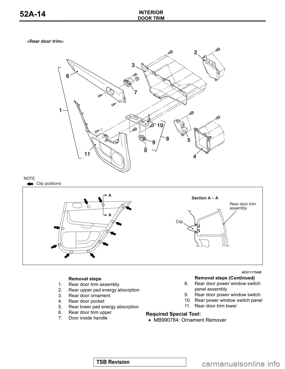
Required Special Tool:
•MB990784: Ornament Remover
AC611175
A
ASection A – A
Clip
Rear door trim
assembly
16
11 2
3
8
10
9 5
4
NOTE : Clip positions
AB
7
Removal steps
1.Rear door trim assembly
2.Rear upper pad energy absorption
3.Rear door ornament
4.Rear door pocket
5.Rear lower pad energy absorption
6.Rear door trim upper
7.Door inside handle
8.Rear door powe r window switch
panel assembly
9.Rear door powe r window switch
10.Rear power window switch panel
11 .Rear door trim lower
Removal steps (Continued)
Page 176 of 241
HEADLINING
TSB Revision
INTERIOR52A-15
HEADLINING
REMOVAL AND INSTALLATIONM1521001400973
Pre-removal and Post-installation Operation
•Removal and Installation of Front Pillar Trim, Upper Cen-
ter Pillar Trim, Rear Pillar Trim (Refer to P.52A-10).
•Removal and Installation of Instrument Under Cover
(Refer to
P.52A-6).
AC609656
2
6
1
1
1
1
3 4
45
5
7
7
8
8
9 8
9 10
10
8
AB
A
A
Section A – AClip
Claw
8
3
Note
(1) : Clip positions
(2) : Claw positions
Page 177 of 241

HEADLINING
TSB Revision
INTERIOR52A-16
Required Special Tool:
•MB990784: Ornament Remover
REMOVAL SERVICE POINTS
.
<> SUN VISOR HOLDER REMOVAL
Insert the special tool MB990784 into side claws of the sun
visor holder through the both sides of the sun visor holder to
remove the hinges.
.
<> HEADLINING ASSEMBLY REMOVAL
To remove the clip, insert a vinyl cord into a clearance between
the clip and the headlining, and pass it around the clip. Then,
pull out the clip downwards while pulling the vinyl cord.
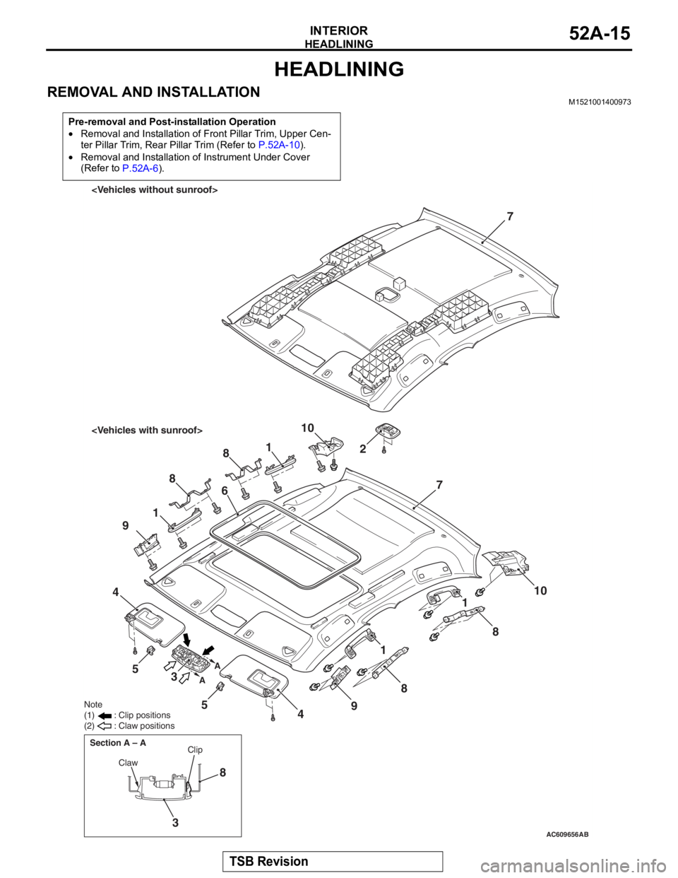
Removal steps
1.Assist grip
2.Rear dome light assembly
3.Front dome light
4.Sun visor assembly
<>5.Sun visor holder
6.Sunroof lid inner weather strip rear
<>7.Headlining
8.Assist grip bracket
9.Front side roof energy absorption box
10.Rear side roof energy absorption box
Removal steps (Continued)
AC005512
MB990784
MB990784
Sun visor holder
AF
AC600751AD
Clip
Headlining Vinyl cord
Page 178 of 241
INSIDE REAR VIEW MIRROR
TSB Revision
INTERIOR52A-17
INSIDE REAR VIEW MIRRORM1521002600561
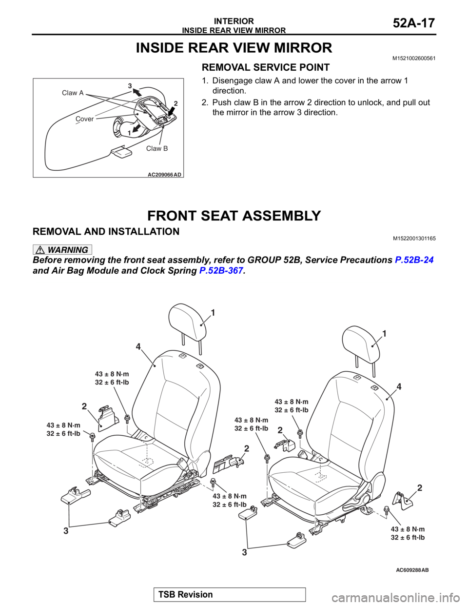
REMOVAL SERVICE POINT
1. Disengage claw A and lower the cover in the arrow 1 direction.
2. Push claw B in the arrow 2 direction to unlock, and pull out the mirror in the arrow 3 direction.
FRONT SEAT ASSEMBLY
REMOVAL AND INSTALLATIONM1522001301165
WARNING
Before removing the front seat assembly, refer to GROUP 52B, Service Precautions P.52B-24
and Air Bag Module and Clock Spring P.52B-367.
AC209066
Claw B
Claw A
Cover
12
3
AD
AC609288AB
4
3 1
43 ± 8 N·m
32 ± 6 ft-lb
43 ± 8 N·m
32 ± 6 ft-lb
43 ± 8 N·m
32 ± 6 ft-lb
43 ± 8 N·m
32 ± 6 ft-lb 43 ± 8 N·m
32 ± 6 ft-lb
43 ± 8 N·m
32 ± 6 ft-lb
1
4
2
2
2
3
2
Page 179 of 241
FRONT SEAT ASSEMBLY
TSB Revision
INTERIOR52A-18
REMOVAL SERVICE POINT
.
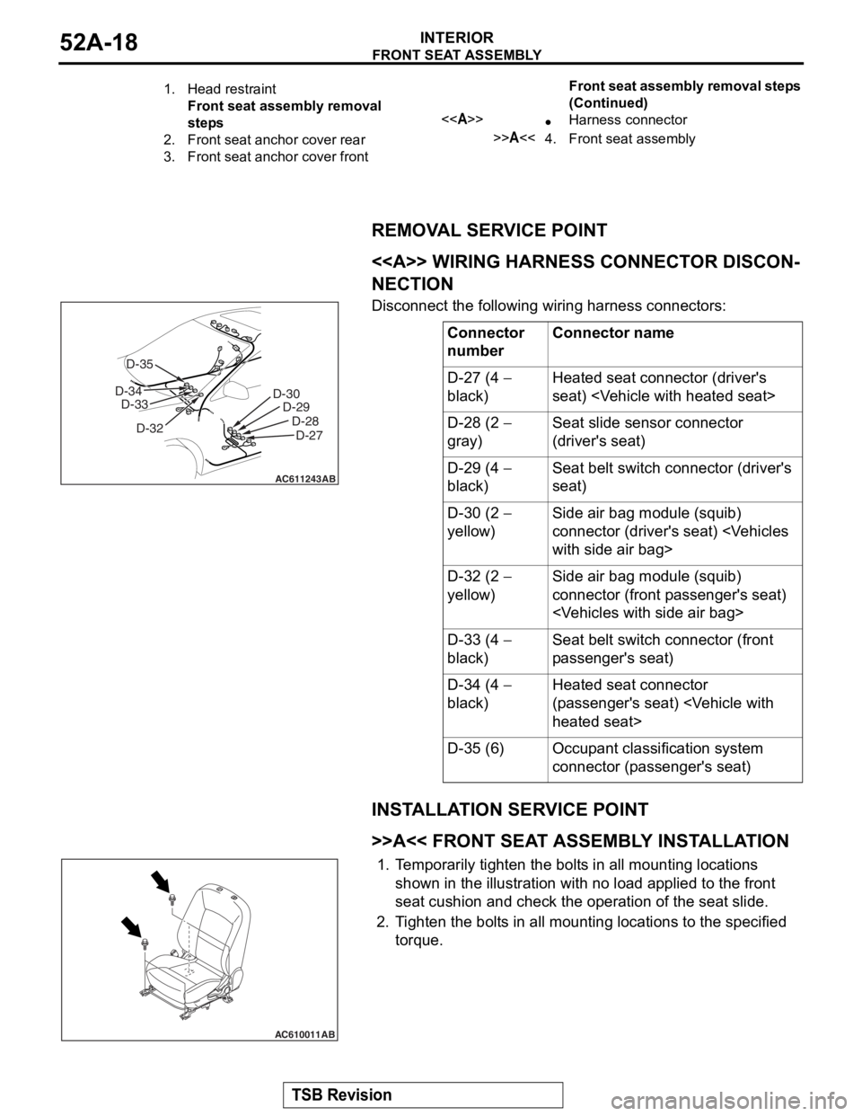
<> WIRING HARNESS CONNECTOR DISCON-
NECTION
Disconnect the following wiring harness connectors:
INSTALLATION SERVICE POINT
.
>>A<< FRONT SEAT ASSEMBLY INSTALLATION
1.Temporarily tighten the bolts in all mounting locations
shown in the illustration with no load applied to the front
seat cushion and check the operation of the seat slide.
2. Tighten the bolts in all mounti ng locations to the specified
torque.
1.Head restraint
Front seat assembly removal
steps
2.Front seat anchor cover rear
3.Front seat anchor cover front
<>•Harness connector
>>A<<4.Front seat assembly
Front seat assembly removal steps
(Continued)
Connector
numberConnector name
D-27 (4 −
black)Heated seat connector (driver's
seat)
D-28 (2 −
gray)Seat slide sensor connector
(driver's seat)
D-29 (4 −
black)Seat belt switch connector (driver's
seat)
D-30 (2 −
yellow)Side air bag module (squib)
connector (driver's seat)
D-32 (2 −
yellow)Side air bag module (squib)
connector (front passenger's seat)
D-33 (4 −
black)Seat belt switch connector (front
passenger's seat)
D-34 (4 −
black)Heated seat connector
(passenger's seat)
D-35 (6)Occupant classification system
connector (passenger's seat)
AC611243
D-30 D-29
D-28D-27
AB
D-32
D-33
D-34 D-35
AC610011AB
Page 180 of 241
FRONT SEAT ASSEMBLY
TSB Revision
INTERIOR52A-19
INSPECTIONM1522005500287
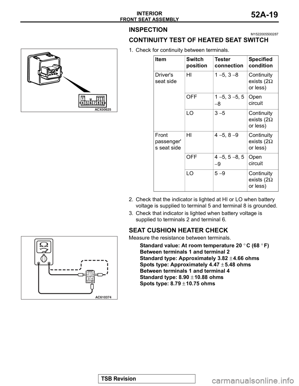
CONTINUITY TEST OF HEATED SEAT SWITCH
.1. Check for continuity between terminals.
2. Check that the indicator is lighted at HI or LO when battery voltage is supplied to terminal 5 and terminal 8 is grounded.
3. Check that indicator is lighted when battery voltage is
supplied to terminal s 2 and terminal 6.
.
SEAT CUSHION HEATER CHECK
Measure the resistance between terminals.
Standard value: At room temperature 20 °C (68 °F)
Between terminals 1 and terminal 2
Standard type: Approximately 3.82 ± 4.66 ohms
Spots type: Approximately 4.47 ± 5.48 ohms
Between terminals 1 and terminal 4
Standard type: 8.90 ± 10.88 ohms
Spots type: 8.79 ± 10.75 ohms
.
ItemSwitch
positionTester
connectionSpecified
condition
Driver's
seat sideHI1 − 5, 3 − 8Continuity
exists (2
Ω
or less)
OFF1 − 5, 3 − 5, 5
− 8
Open
circuit
LO3 − 5Continuity
exists (2
Ω
or less)
Front
passenger'
s seat sideHI4 − 5, 8 − 9Continuity
exists (2
Ω
or less)
OFF4 − 5, 5 − 8, 5
− 9
Open
circuit
LO5 − 9Continuity
exists (2
Ω
or less)
ACX00625
AC610374