MITSUBISHI LANCER IX 2006 Service Manual
Manufacturer: MITSUBISHI, Model Year: 2006, Model line: LANCER IX, Model: MITSUBISHI LANCER IX 2006Pages: 800, PDF Size: 45.03 MB
Page 181 of 800
Page 182 of 800

NOTES
Page 183 of 800
33-1
GROUP 33
FRONT
SUSPENSION
CONTENTS
GENERAL INFORMATIO N . . . . . . . .33-2
SERVICE SPECIFICATIONS . . . . . . .33-3
LUBRICANT . . . . . . . . . . . . . . . . . . . .33-3
SPECIAL TOOLS . . . . . . . . . . . . . . . .33-4
ON-VEHICLE SERVICE . . . . . . . . . . .33-6
FRONT WHEEL ALIGNMENT CHECK AND
ADJUSTMENT . . . . . . . . . . . . . . . . . . . . . . 33-6
LOWER ARM BALL JOINT AXIAL PLAY
CHECK . . . . . . . . . . . . . . . . . . . . . . . . . . . . 33-7
LOWER ARM BALL JOINT COVER
CHECK . . . . . . . . . . . . . . . . . . . . . . . . . . . . 33-7
STRUT ASSEMBLY . . . . . . . . . . . . . .33-7
REMOVAL AND INSTALLATION . . . . . . . . 33-7
INSPECTION. . . . . . . . . . . . . . . . . . . . . . . . 33-7
DISASSEMBLY AND REASSEMBLY . . . . . 33-8
INSPECTION. . . . . . . . . . . . . . . . . . . . . . . . 33-10
LOWER ARM . . . . . . . . . . . . . . . . . . .33-11
REMOVAL AND INSTALLATION . . . . . . . . 33-11
INSPECTION. . . . . . . . . . . . . . . . . . . . . . . . 33-12
LOWER ARM BALL JOINT COVER
REPLACEMENT . . . . . . . . . . . . . . . . . . . . . 33-12
LOWER ARM BUSHING (REAR)
REPLACEMENT . . . . . . . . . . . . . . . . . . . . . 33-13
STABILIZER BAR. . . . . . . . . . . . . . . .33-14
REMOVAL AND INSTALLATION . . . . . . . . 33-14
INSPECTION. . . . . . . . . . . . . . . . . . . . . . . . 33-16
WARNINGS REGARDING SERVICING OF SUPPLEMENTAL RESTRAINT SYSTEM (SRS) EQUIPPED VEHICLES
WARNING
•Improper service or maintenance of any component of the SRS, or any SRS-related component, can lead to
personal injury or death to service personnel (from inad vertent firing of the air bag) or to the driver and
paassenger (from rendering the SRS inoperative).
•Service or maintenance of any SRS component or SRS-related component must be performed only at an
authorized MITSUBISHI dealer.
•MITSUBISHI dealer personnel must thoroughly review this manual, and especially its GROUP 52B - Supplemental
Restraint System (SRS) before beginning any service or maintenance of any component of the SRS or any
SRS-related component.
NOTE
The SRS includes the following components: SRS air bag control unit, SRS warning light, front impact sensors, air bag module,
clock spring, and interconnecting wiring. Other SRS-related components (that may have to be removed/installed in connection
with SRS service or maintenance) are indicated in the table of contents by an asterisk (*).
Page 184 of 800
GENERAL INFORMATION
FRONT SUSPENSION33-2
GENERAL INFORMATION
M1332000100537
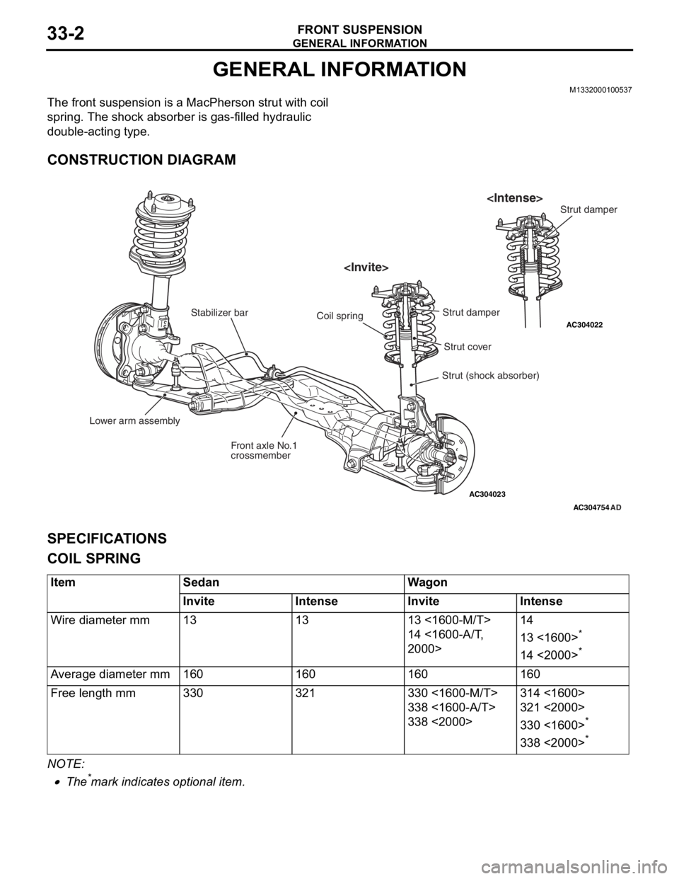
The front suspension is a MacPherson strut with coil
spring. The shock absorber is gas-filled hydraulic
double-acting type.
CONSTRUCTION DIAGRAM
AC304023
AC304022
AC304754
Lower arm assembly Front axle No.1
crossmember
Stabilizer bar
Strut (shock absorber)
Coil spring
AD
Strut cover
Strut damper
SPECIFICA
T IONS
COIL SPRING
ItemSedanWagon
InviteIntenseInviteIntense
Wire diameter mm131313 <1600-M/T>
14 <1600-A/T,
2000>
14
13 <1600>*
14 <2000>*
Average diameter mm160160160160
Free length mm330321330 <1600-M/T>
338 <1600-A/T>
338 <2000>
314 <1600>
321 <2000>
330 <1600>*
338 <2000>*
NOTE: .
•The*mark indicat e s op tiona l it em.
Page 185 of 800

SERVICE SPECIFICATIONS
FRONT SUSPENSION33-3
SERVICE SPECIFICATIONS
M1332000300746
ItemStandard value
Toe-inAt the centre of tyre tread mm1 ± 2
Toe-angle (per wheel)0°03' ± 0°06'
Toe-out angle on turns (inner wheel when outer wheel at 20°)21°42' ± 1°30'
Steering angleInner wheelInvite39°30' ± 1°30'
Intense (LH drive vehicles)33°40' +1°00'/−2°00'
Intense (RH drive vehicles)37°00' +1°00'/−2°00'
Outer wheel (reference)Invite32°30'
Intense (LH drive vehicles)28°46'
Intense (RH drive vehicles)30°00'
CamberInvite0°05' ± 0°30'*
Intense−0°05' ± 0°30'*
CasterInvite2°45' ± 0°30'*
Intense2°55' ± 0°30'*
Kingpin inclinationInvite12°30' ± 1°30'
Intense12°40' ± 1°30'
Lower arm ball joint starting torque N⋅m0 − 3.9
Protruding length of stabilizer link thread part mm22 ± 1.5
NOTE: *: Difference between right and left wheels must be less than 30'
LUBRICANT
M1332000400152
ItemSpecified lubricantQuantity
Lower arm ball jointLip portion of ball joint coverMultipurpose grease SAE J310,
NLGI No.2 or equivalentAs required
Inside of ball joint cover
Page 186 of 800
SPECIAL TOOLS
FRONT SUSPENSION33-4
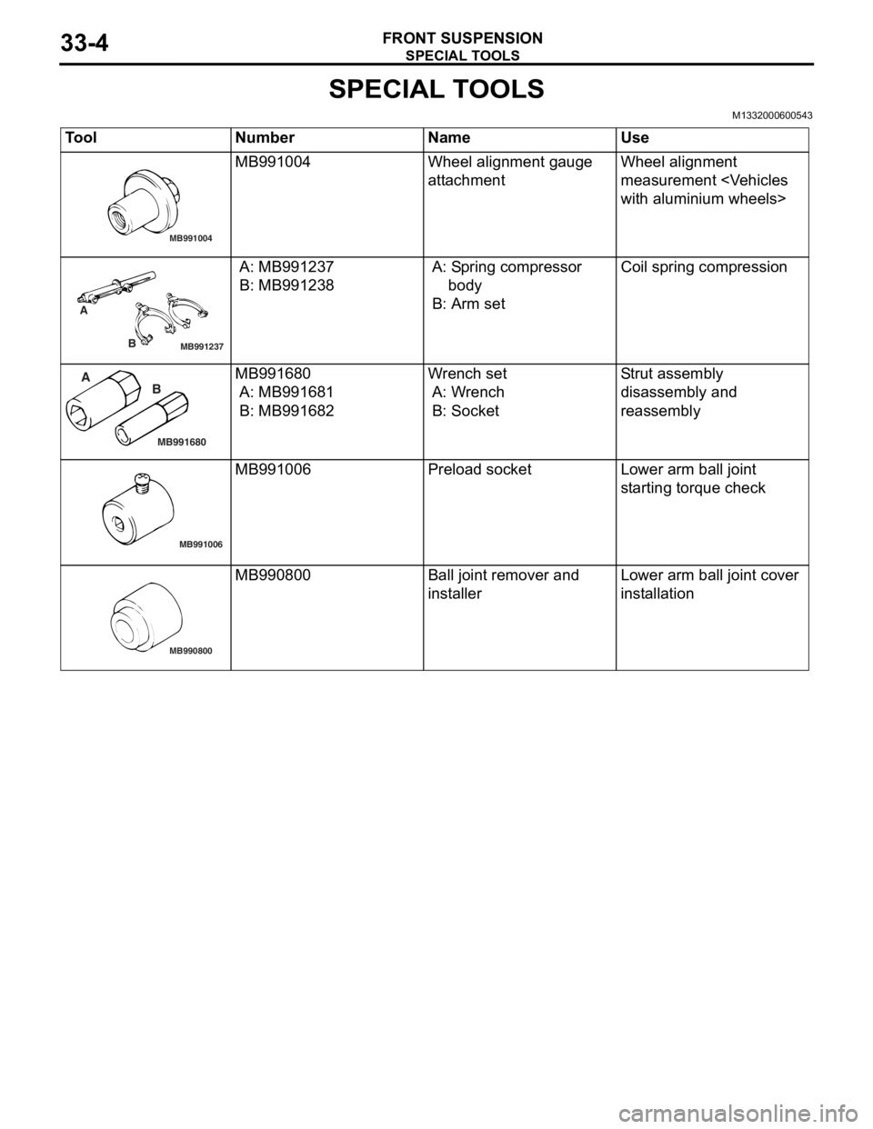
SPECIAL TOOLS
M1332000600543
ToolNumberNameUse
MB991004
MB991004Wheel alignme n t gau ge
att
a chmentWheel alig nme n t
measurement
with aluminium wheels>
MB991237
A
B
A: MB9912 37
B: MB991238
A: Sp ring compressor
b ody
B: Arm set
Coil spring compression
MB991680
A BMB991680
A: MB9916 81
B: MB991682
Wr ench set
A: W r ench
B: Socket
Str u t a s s e m b l y
d
i sa ssembly an d
reassembly
MB991006
MB991006Prel oad socketLo wer arm ball joint
st
arting torque check
MB990800
MB990800Ball j o int remo ver an d
inst
al lerLo wer arm ball joint cover
inst
allation
Page 187 of 800
MB990883
SPECIA L T OOLS
FRONT SU SPENSION33-5
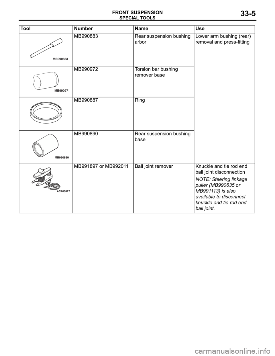
MB990883Rear suspension bushing
arborLo wer arm bushing (rear)
re
moval a nd press-fittin g
MB990971
MB990972To rsion b a r bushin g
remover base
MB990887Ring
MB990890
MB990 890Rear suspension bushing
base
AC106827
MB991897 or MB9920 1 1Ball j o int remo verKnuckle an d tie rod end
b
a ll joint disco nnection
NOTE: St eering linka ge
p
u
ller (MB99 0635 o r
MB991
1 13) is also
a
v
ailable to d i sconne ct
knuckle and t i e rod end
b
a
ll
joi
n t.
T ool Nu mber Na me Use
Page 188 of 800
ON-VEHICLE SERVICE
FRONT SUSPENSION33-6
ON-VEHICLE SERVICE
FRONT WHEEL ALIGNMENT CHECK AND
ADJUSTMENT
M1331000900886
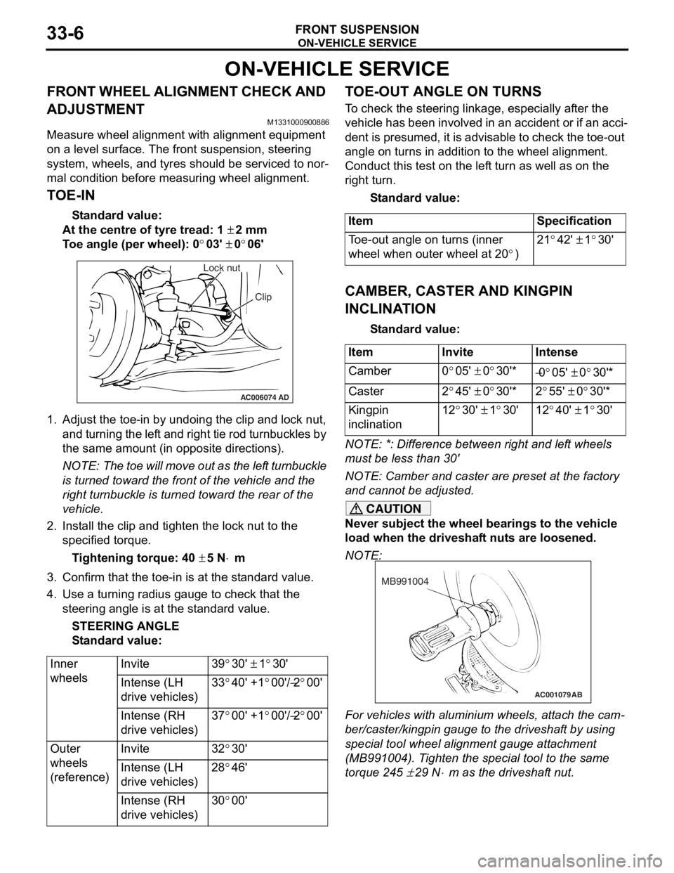
Measure wheel alignment with alignment equipment
on a level surface. The front suspension, steering
system, wheels, and tyres should be serviced to nor
-
mal condition before measuring wheel alignment.
TOE-IN
Standard value:
At the centre of tyre tread: 1 ± 2 mm
Toe angle (per wheel): 0°03' ± 0°06'
AC006074 AD
Lock nut
Clip
1.Adjust the to e-in by undoing th e clip and lock nut,
and turning th e lef t and rig h t tie rod turnbu ckles by
th e same amount (in op posite direct ions).
NOTE: The toe will move out as th e lef t turnbuckle
is turn
ed toward the fro n t of th e ve hicle an d the
right tu
rnbuckle is turned t o ward the rear of the
vehicle.
2. In st all the clip and tighten the lock nut to the
specifie d torqu e .
Ti ghte n ing torque: 40 ± 5 N⋅m
3.Conf irm t hat the toe-in is at the st anda rd value.
4.Use a turn ing ra dius gaug e to check tha t the
steering ang le is at the st an dard value .
STEE R I N G AN G L E
St andard va lue:
Inner
wheelsInvite39°30' ± 1°30'
Intense (LH
drive vehicles)33°40' +1°00'/−2°00'
Intense (RH
drive vehicles)37°00' +1°00'/−2°00'
Outer
wheels
(reference)Invite32°30'
Intense (LH
drive vehicles)28°46'
Intense (RH
drive vehicles)30°00'
TO E-OUT ANGLE ON TURNS
To check the stee ring linkage, e s pe cially af ter the
vehicle has been invo
lve d in an accid ent or if an a cci
-
dent is pres umed, it is advisab le to check th e toe-ou t
angle
on tu rns in addition to the wh eel a lig nmen t.
Conduct this test on th e lef t tu rn as we ll a s on the
right turn.
St andard va lue:
ItemSpecification
Toe-out angle on turns (inner
wheel when outer wheel at 20
°)
21°42' ± 1°30'
CAMBER, CASTER AND KINGPIN
INCLINA
T ION
St andard va lue:
ItemInviteIntense
Camber0°05' ± 0°30'*−0°05' ± 0°30'*
Caster2°45' ± 0°30'*2°55' ± 0°30'*
Kingpin
inclination12°30' ± 1°30'12°40' ± 1°30'
NOTE: *: Diffe rence between right and lef t wheels
must be less than 30'
NOTE: Camber and caster are prese t at th e factory
and cannot be adjust ed.
CAUTION
Never subject the wheel bearings to the vehicle
load when the driveshaft nuts are loosened.
NOTE:
AC001079
MB991004
AB
For vehicles with aluminium wheels, attach the cam-
ber/caster/kingpin gauge to the driveshaft by using
special tool wheel alignment gauge attachment
(MB991004). Tighten the special tool to the same
torque 245
± 29 N⋅m as the driveshaft nut.
Page 189 of 800
STRUT ASSEMBLY
FRONT SUSPENSION33-7
LOWER ARM BALL JOINT AXIAL PLAY
CHECK
M1332011300074
1. Raise the vehicle.
2. Remove the stabilizer link from the lower arm.
3. Move the lower arm up and down with your hands to check for an excessive play in the axial
direction of the ball joint. If there is an excessive
play, replace the lower arm assembly.
LOWER ARM BALL JOINT COVER
CHECK
M1332008600321
1. Press the lower arm ball joint cover with your finger to check that there are no cracks or
damage in the lower arm ball joint cover.
2. If the lower arm ball joint cover is cracked or damaged, replace the lower arm assembly.
NOTE: If the lower arm ball joint cover is cracked
or damaged, it is possible that there may also be
damage to the ball joint.
STRUT ASSEMBLY
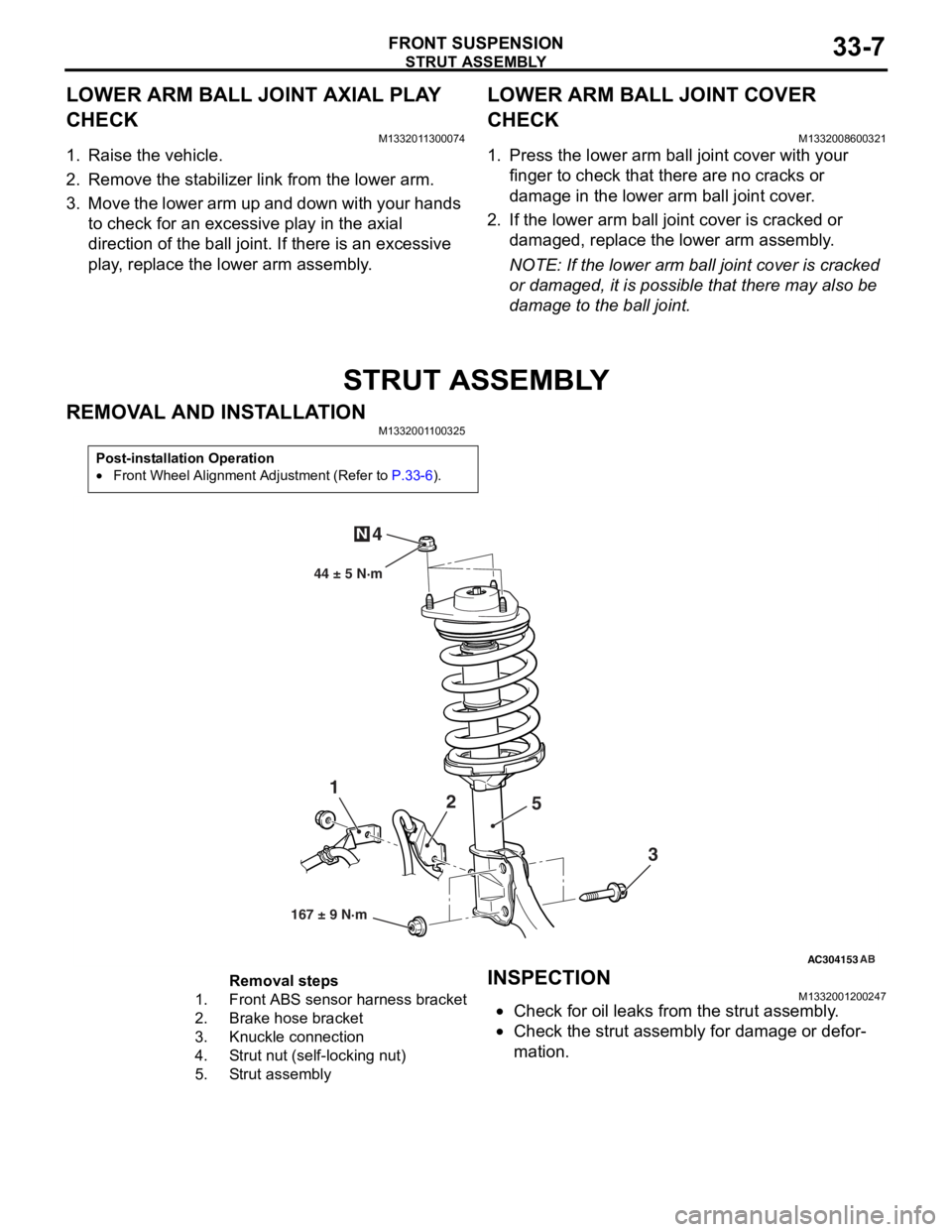
REMOVAL AND INSTALLATION
M1332001100325
Post-installation Operation
•Front Wheel Alignment Adjustment (Refer to P.33-6).
AC304153
44 ± 5 N·m
1 2
3
4
N
AB
167 ± 9 N·m
5
Removal steps
1.Front ABS sensor
harness bracket
2.Brake hose bracket
3.Knuckle connection
4.Strut nut (self-locking nut)
5.Strut assembly
INSPECTION
M13320012 0024 7
•Check for oil leaks fro m the stru t assemb ly .
•Check the stru t assemb ly for damage o r defor-
mation.
Page 190 of 800
STRUT ASSEMBLY
FRONT SUSPENSION33-8
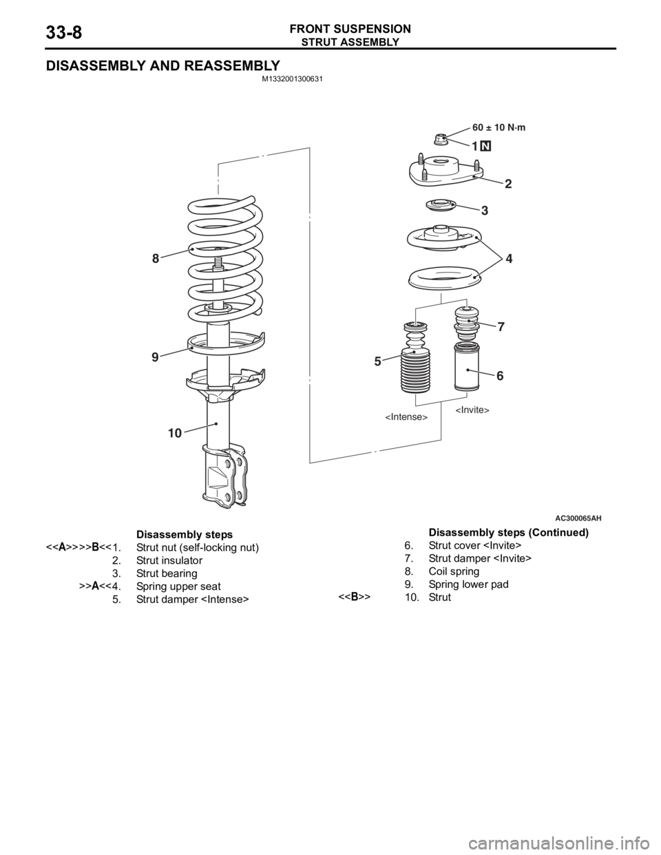
DISASSEMBLY AND REASSEMBLY
M1332001300631
AC300065
60 ± 10 N·m
2
1
N
AH
3
4
5
6
7
8
9
10
Disassembly steps
<>>>B<<1.Strut nut (self-locking nut)
2.Strut insulator
3.Strut bearing
>>A<<4.Spring upper seat
5.Strut damper
6.Strut cover
7.Strut damper
8.Coil spring
9.Spring lower pad
<>10.Str ut
Disassembly steps (Continued)