MITSUBISHI SPYDER 1990 Service Repair Manual
SPYDER 1990
MITSUBISHI
MITSUBISHI
https://www.carmanualsonline.info/img/19/57345/w960_57345-0.png
MITSUBISHI SPYDER 1990 Service Repair Manual
Trending: oil reset, check engine light, mileage, flat tire, oil change, spare wheel, trailer
Page 111 of 2103
ENGINE OVERHAUL
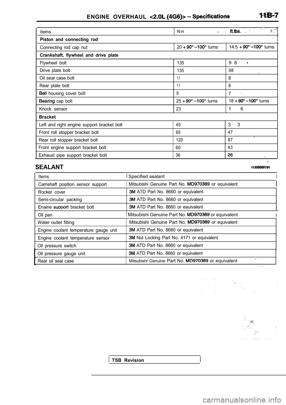
items
Piston and connecting rod
Connecting rod cap nut
Crankshaft, flywheel and drive plate
Flywheel bolt
Drive plate bolt
Oil seal case bolt
Rear plate bolt
housing cover bolt
cap bolt
Knock sensor
Bracket
Left and right engine support bracket bolt
Front roll stopper bracket bolt
Rear roll stopper bracket bolt
Front engine support bracket bolt
Exhaust pipe support bracket bolt
N m
20 turns 14.5 turns
1359 8
135 98
118
118
97
25 turns18 turns
231 6
453 3
65 47
120 87
60 43
36
SEALANT
Items Specified sealantI
Camshaft position sensor support Mitsubishi Genuine Part No. or equivalent
Rocker cover
Semi-circular packing
Enaine
bracket bolt
ATD Part No. 8660 or equivalent
ATD Part No. 8660 or equivalent
ATD Part No. 8660 or eauivalent
Oil pan Mitsubishi Genuine Part No. or equivalentI
Water outlet fitting
Engine coolant temperature gauge unit
Engine coolant temperature sensor
Oil pressure switch Mitsubishi Genuine Part No. or equivalent
ATD Part No. 8660 or equivalent
Nut Locking Part No. 4171 or equivalent
ATD Part No. 8660 or equivalent
Oil pressure gauge unit
ATD Part No. 8660 or equivalent
Rear oil seal case
Mitsubishi Genuine Part No. or equivalent
TSB Revision
Page 112 of 2103
ENGINE OVERHAUL ,
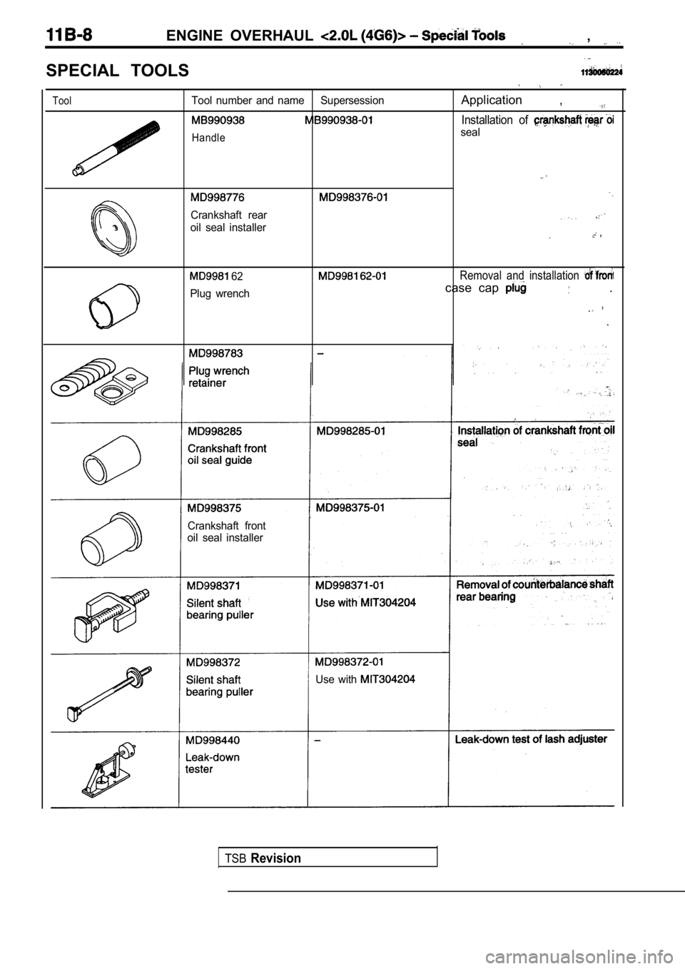
SPECIAL TOOLS
ToolTool number and name SupersessionApplication ,
Installation of
Handleseal
Crankshaft rear
oil seal installer ,
62Removal and installation
Plug wrenchcase cap .
Crankshaft front
oil seal installer
Use with
TSBRevision
Page 113 of 2103
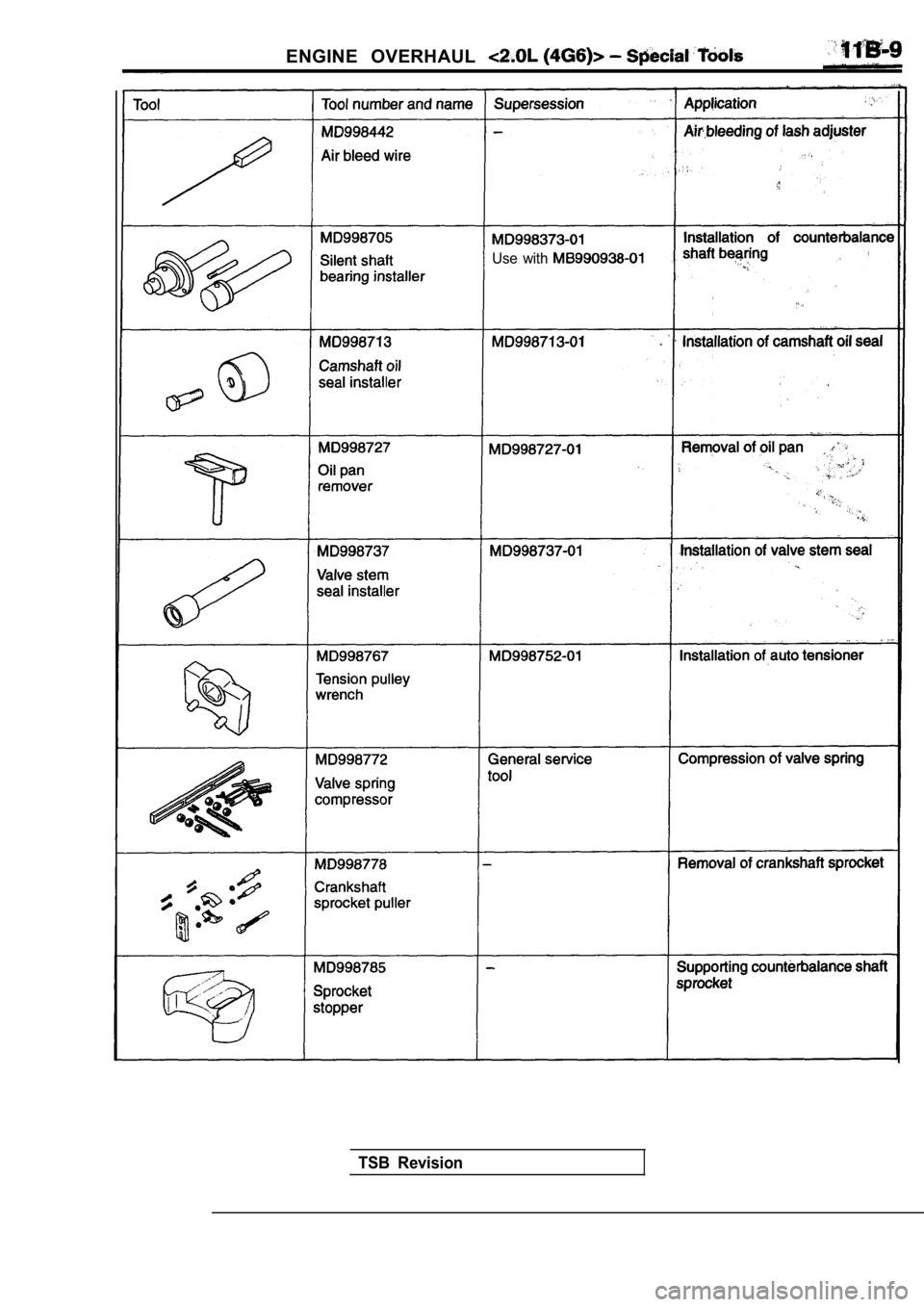
ENGINE OVERHAUL
Use with
TSB Revision
Page 114 of 2103
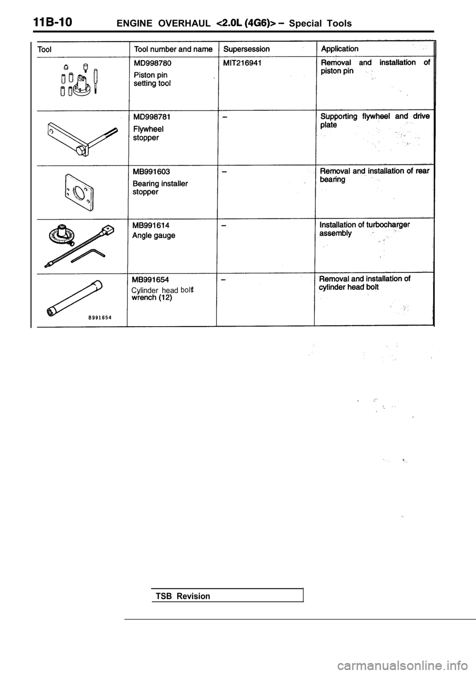
ENGINE OVERHAUL Special Tools
Cylinder headbolt
TSB Revision
Page 115 of 2103
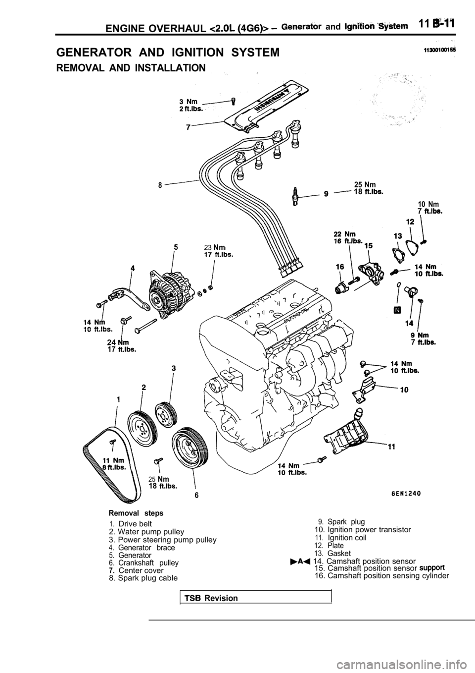
ENGINE OVERHAUL and 11
GENERATOR AND IGNITION SYSTEM
REMOVAL AND INSTALLATION
825 Nm 18
523Nm
24177
25Nm18
6
10 Nm7
Removal steps
1.Drive belt
2. Water pump pulley
3. Power steering pump pulley
4.Generator brace5.Generator6.Crankshaft pulley7.Center cover
8. Spark plug cable
9.Spark plug10. Ignition power transistor
11.Ignition coil12. Plate
13.Gasket 14. Camshaft position sensor 15. Camshaft position sensor
16. Camshaft position sensing cylinder
Revision
Page 116 of 2103
ENGINE OVERHAUL Generator and
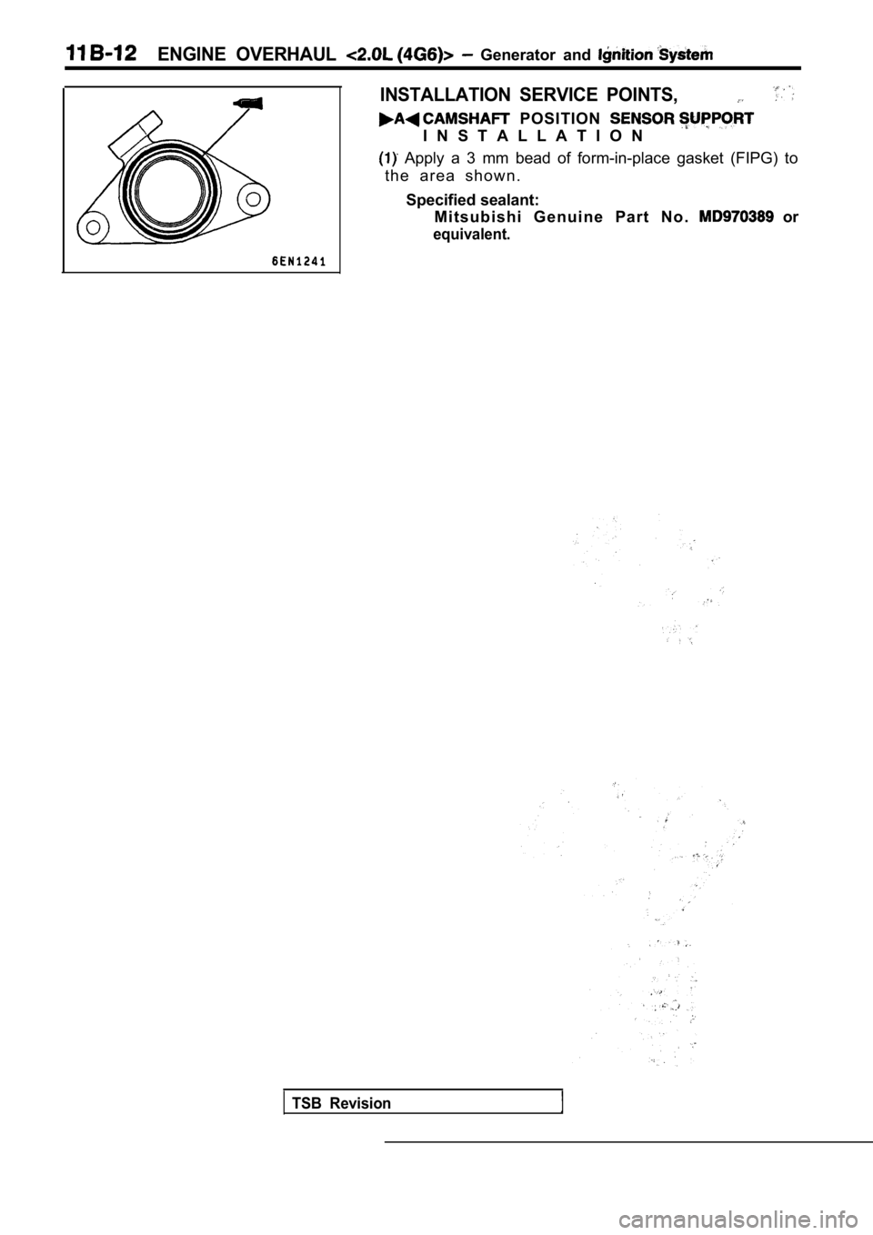
INSTALLATION SERVICE POINTS,
POSITION
I N S T A L L A T I O N
Apply a 3 mm bead of form-in-place gasket (FIPG) to
t h e a r e a s h o w n .
Specified sealant: M i t s u b i s h i G e n u i n e P a r t N o .
or
equivalent.
TSB Revision
Page 117 of 2103
ENGINE OVERHAUL
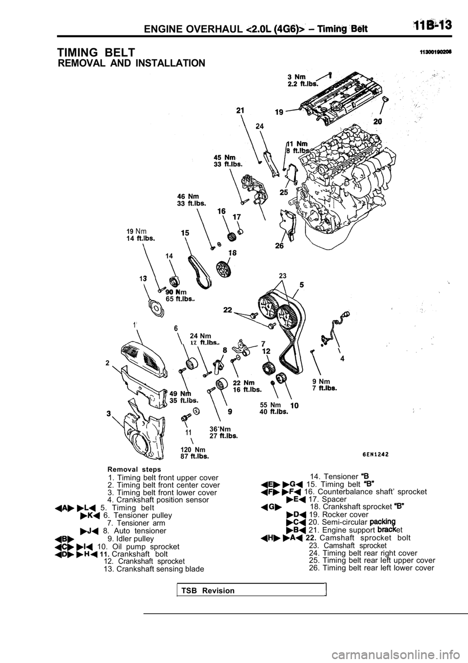
TIMING BELT
REMOVAL AND INSTALLATION
19N m
24
14
14
13
90 Nm65
23
1624 Nm17
24
9 Nm7
.1136 Nm27
120 Nm87
Removal steps
1. Timing belt front upper cover
2. Timing belt front center cover
3. Timing belt front lower cover
4. Crankshaft position sensor
5. Timing belt 6. Tensioner pulley7. Tensioner arm 8. Auto tensioner
9. Idler pulley
10. Oil pump sprocket 11. Crankshaft bolt12. Crankshaft sprocket13. Crankshaft sensing blade
55 Nm40
14. Tensioner 15. Timing belt 16. Counterbalance shaft’ sprocket 17. Spacer18. Crankshaft sprocket
19. Rocker cover 20. Semi-circular
21. Engine support et
22. Camshaft sprocket bolt23. Camshaft sprocket24. Timing belt rear right cover
25. Timing belt rear left upper cover
26. Timing belt rear left lower cover
TSB Revision
Page 118 of 2103
OVERHAUL Timing. Belt
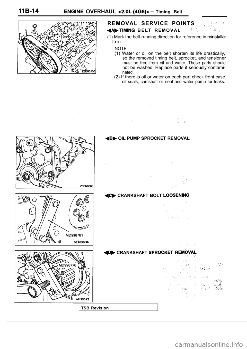
R E M O V A L S E R V I C E P O I N T S
B E L T R E M O V A L
(1) Mark the belt running direction for reference in
t i o n .
NOTE
(1) Water or oil on the belt shorten its life drast ically,
so the removed timing belt, sprocket, and tensioner
must be free from oil and water. These parts should
not be washed. Replace parts if seriously contami-
nated.
(2) If there is oil or water on each part check fro nt case
oil seals, camshaft oil seal and water pump for lea ks.
OIL PUMP SPROCKET REMOVAL
CRANKSHAFT BOLT
CRANKSHAFT . .
TSB Revision
Page 119 of 2103
OVERHAUL Timing
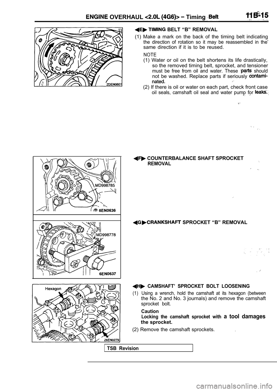
BELT “B” REMOVAL
(1) Make a mark on the back of the timing belt indi cating
the direction of rotation so it may be reassembled in the’
same direction if it is to be reused.
NOTE
(1) Water or oil on the belt shortens its life drastically,
so the removed timing belt, sprocket, and tensioner
must be free from oil and water. These should
not be washed. Replace parts if seriously
(2) If there is oil or water on each part, check fr ont case
oil seals, camshaft oil seal and water pump for
COUNTERBALANCE SHAFT SPROCKET
REMOVAL
SPROCKET “B” REMOVAL
CAMSHAFT’ SPROCKET BOLT LOOSENING
(1)Using a wrench, hold the camshaft at its hexagon (b etween
the No. 2 and No. 3 journals) and remove the camshaft
sprocket bolt.
Caution
Locking the camshaft sprocket with a tool damages
the sprocket.
(2) Remove the camshaft sprockets.
,
TSB Revision
Page 120 of 2103
ENGINE OVERHAUL Timing Belt,
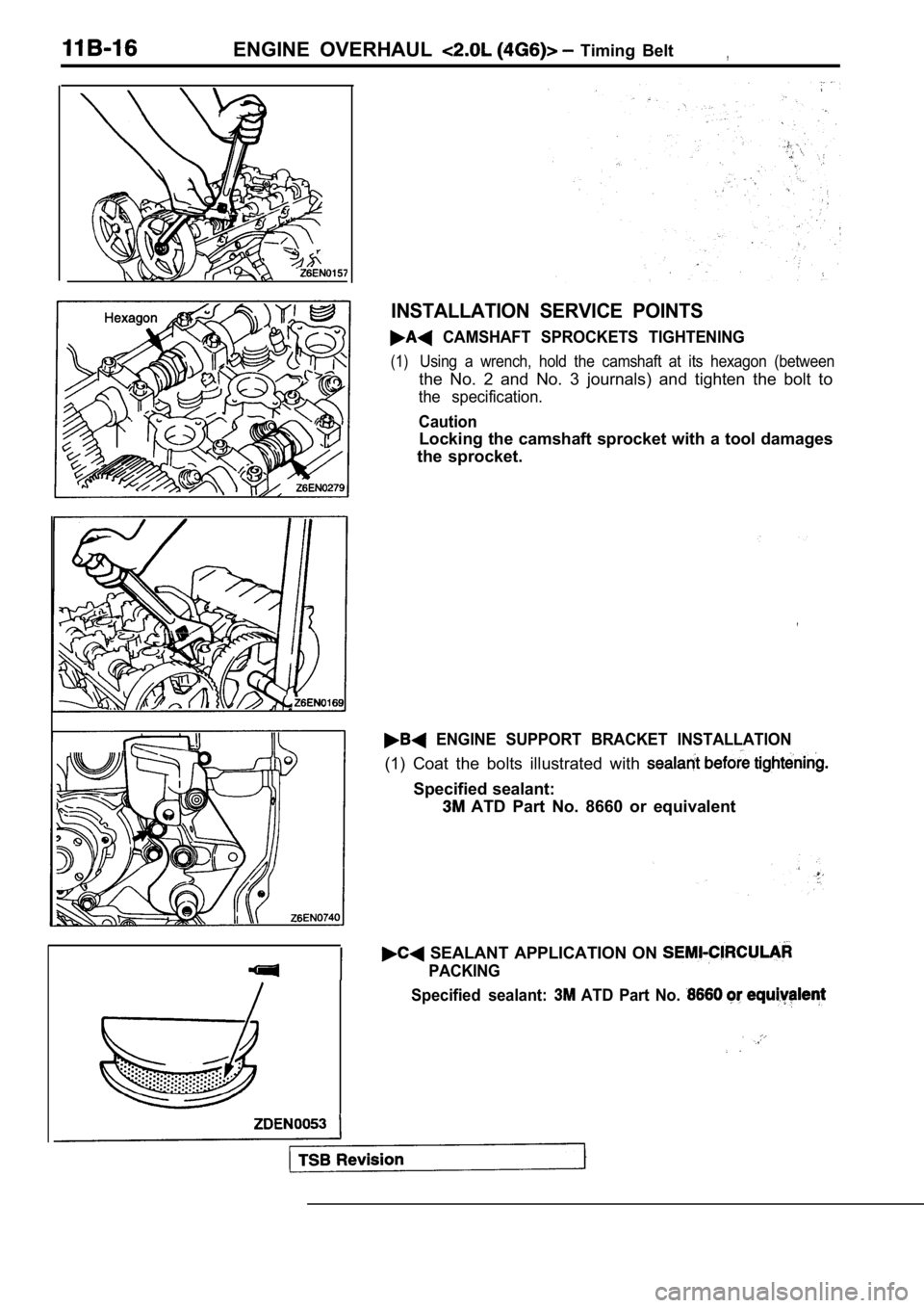
INSTALLATION SERVICE POINTS
CAMSHAFT SPROCKETS TIGHTENING
(1)Using a wrench, hold the camshaft at its hexagon (between
the No. 2 and No. 3 journals) and tighten the bolt to
the specification.
Caution
Locking the camshaft sprocket with a tool damages
the sprocket.
ENGINE SUPPORT BRACKET INSTALLATION
(1) Coat the bolts illustrated with
Specified sealant:
ATD Part No. 8660 or equivalent
SEALANT APPLICATION ON
PACKING
Specified sealant:
ATD Part No.
Trending: run flat, window, service reset, fuses, air bleeding, ECO mode, towing

