MITSUBISHI SPYDER 1990 Service Repair Manual
SPYDER 1990
MITSUBISHI
MITSUBISHI
https://www.carmanualsonline.info/img/19/57345/w960_57345-0.png
MITSUBISHI SPYDER 1990 Service Repair Manual
Trending: instrument panel, oil dipstick, light, driver seat adjustment, tow, wiring, ignition
Page 1491 of 2103
PROPELLER
SHAFT
CONTENTS
ADHESIVE. . . . . . . . . . . . . . . . . . . . . . . . . . . . . . . . .2SERVICE . . . . . . . . . . . 2
GENERAL INFORMATION2SPECIAL. . . . . . . . . . . . . . . . . . . . . . . . . . .3,
LUBRICANTS. . . . . . . . . . . . . . . . . . . . . . . . . . . . . .2TROUBLESHOOTING . . . . . . . . . . . . . . . . . .
. . . . . 3’
Page 1492 of 2103
General Information/Service Specifications/
PROPELLER SHAFT Lubricants/Adhesive
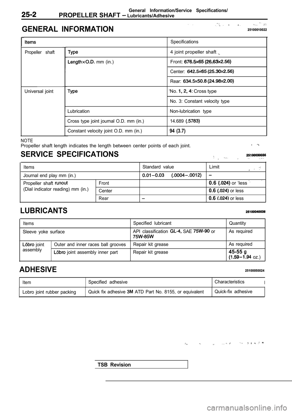
GENERAL INFORMATION
. .
25100010022
Propeller shaft
Universal jointSpecifications
mm (in.)
4 joint propeller shaft
Front:
Center:
Rear:
‘No. Cross type
No. 3: Constant velocity type
Lubrication
Cross type joint journal O.D. mm (in.) Constant velocity joint O.D. mm (in.) Non-lubrication type
14.689
94 (3.7)
NOTE
Propeller shaft length indicates the length between center points of each joint. ,
SERVICE SPECIFICATIONS
ItemsStandard valueLimit
Journal end play mm (in.)
Propeller shaft Front0.6 or ‘less
(Dial indicator reading) mm (in.)
Center0.6 or less
Rear0.6 or less
LUBRICANTS
Items
Sleeve yoke surface Specified lubricant
API classification SAE or
Quantity
As required
joint
assembly Outer and inner races ball grooves
Repair kit grease As required
joint assembly inner part
Repair kit grease45-55
oz.)
25100050024ADHESIVE
ItemSpecified adhesive CharacteristicsI
Lobro joint rubber packingQuick fix adhesive ATD Part No. 8155, or equivalent Quick-fix adhesive
TSB Revision
Page 1493 of 2103
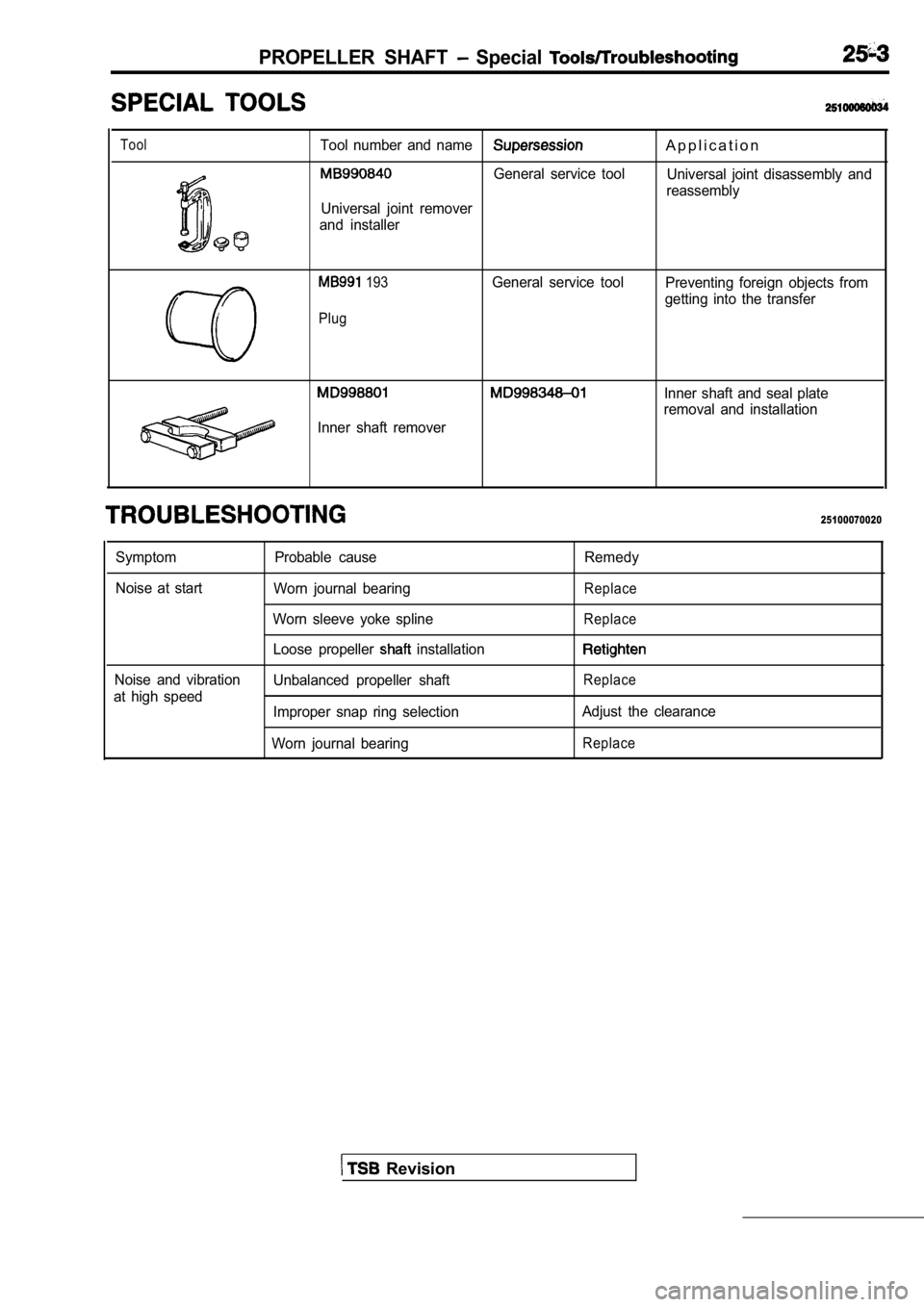
PROPELLER SHAFT Special
ToolTool number and nameA p p l i c a t i o n
General service toolUniversal joint disassembly and
reassembly
Universal joint remover
and installer
193
PlugGeneral service tool Preventing foreign objects from
getting into the transfer
Inner shaft remover
Inner shaft and seal plate
removal and installation
25100070020
Symptom
Noise at start
Noise and vibration
at high speed Probable cause Remedy
Worn journal bearing
Replace
Worn sleeve yoke splineReplace
Loose propeller installation
Unbalanced propeller shaftReplace
Improper snap ring selection Adjust the clearance
Worn journal bearing
Replace
Revision
Page 1494 of 2103
PROPELLER Propeller
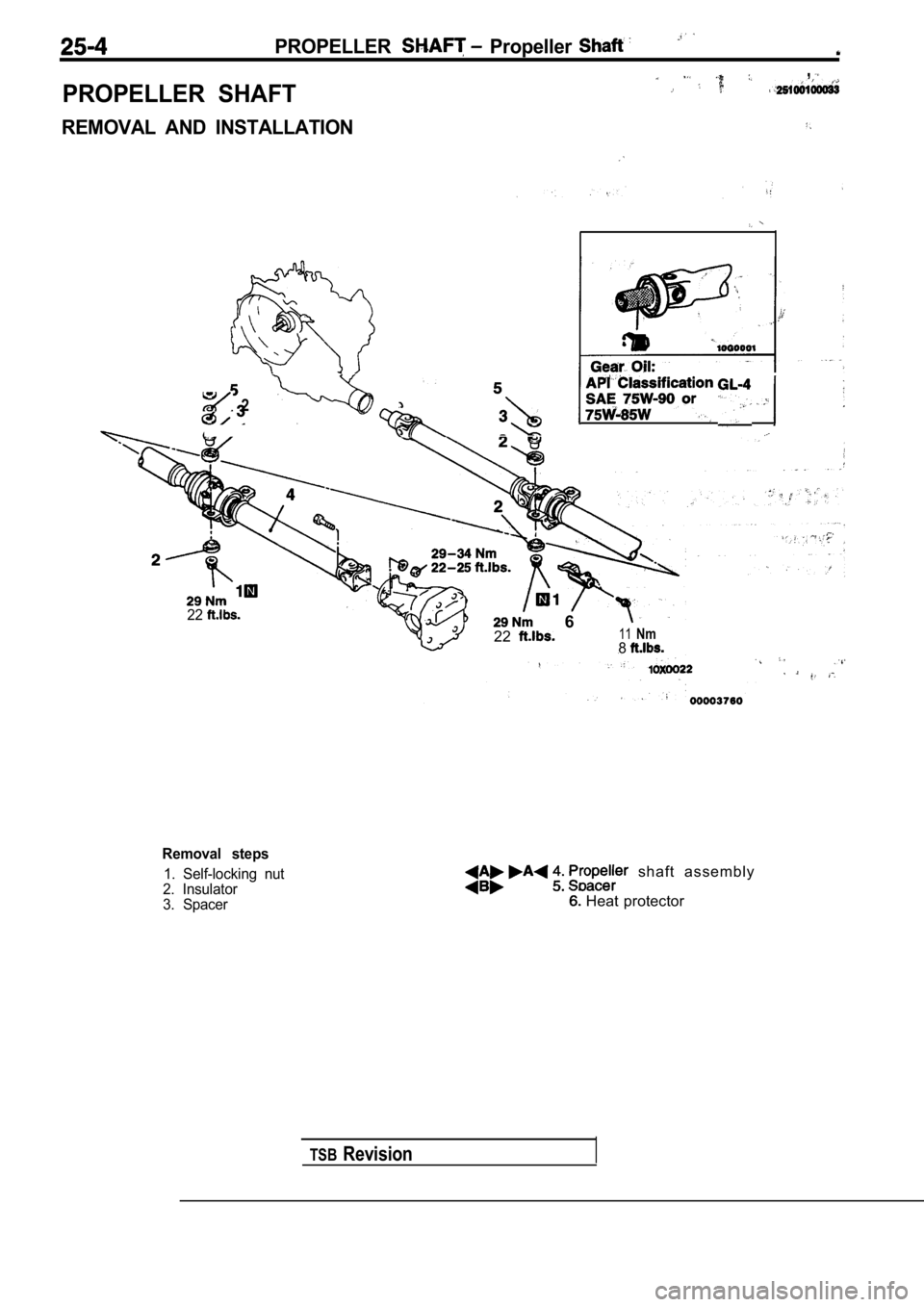
PROPELLER SHAFT
,
REMOVAL AND INSTALLATION
2
22 6
2211Nm8
TSBRevision
Removal steps
1. Self-locking nut
2. Insulator
3. Spacer shaft assembly
Heat protector
Page 1495 of 2103
SHAFT Propeller
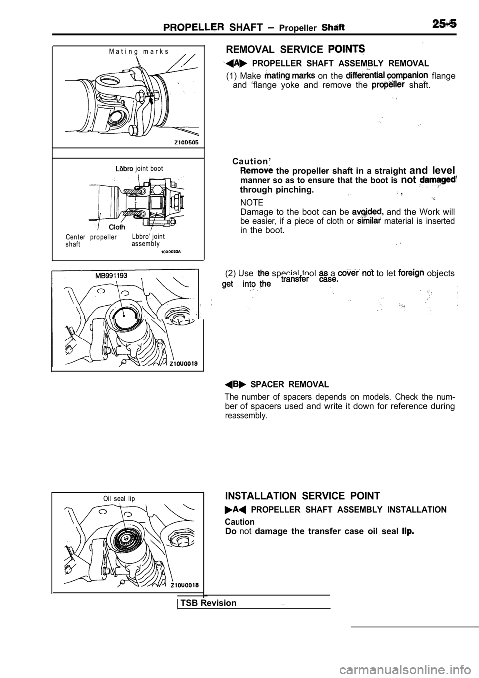
M a t i n g m a r k s
joint boot
Center propeller
shaft Lbbro’ joint
assembly
REMOVAL SERVICE
PROPELLER SHAFT ASSEMBLY REMOVAL
(1) Make on the flange
and ‘flange yoke and remove the
shaft.
. .
C a u t i o n ’
the propeller shaft in a straight and level
manner so as to ensure that the boot is not
through pinching. ,
NOTE
Damage to the boot can be and the Work will
be easier, if a piece of cloth or material is inserted
in the boot.
(2) Use special tool a to let objects
SPACER REMOVAL
The number of spacers depends on models. Check the num-
ber of spacers used and write it down for reference during
reassembly.
Oil seal lipINSTALLATION SERVICE POINT
PROPELLER SHAFT ASSEMBLY INSTALLATION
Caution
Do not damage the transfer case oil seal
TSB Revision. .
Page 1496 of 2103
. . ,
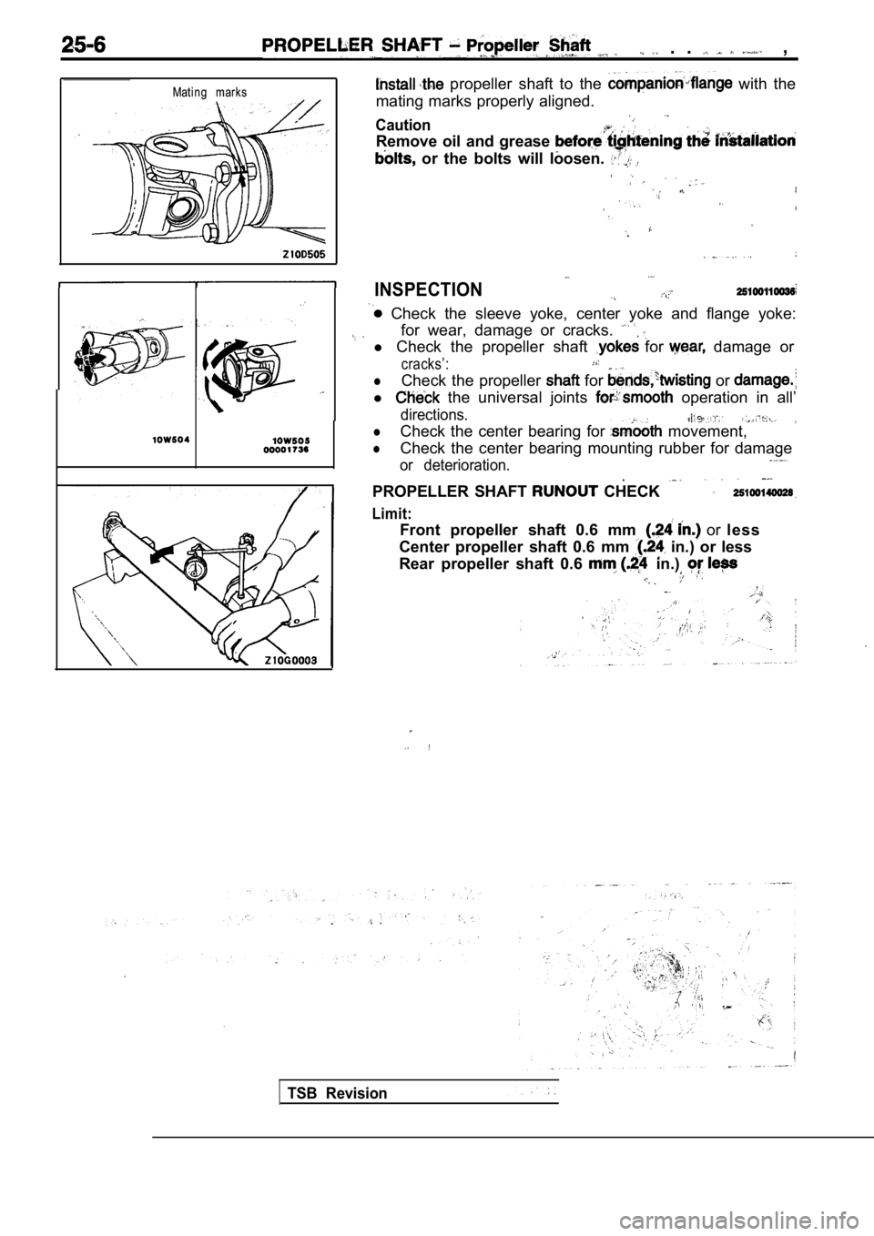
Mating marks
propeller shaft to the with the
mating marks properly aligned.
Caution
Remove oil and grease
or the bolts will loosen.
INSPECTION
Check the sleeve yoke, center yoke and flange yoke :
for wear, damage or cracks.
l Check the propeller shaft for damage or
cracks’:
lCheck the propeller for or
l the universal joints operation in all’
directions.
lCheck the center bearing for movement,
lCheck the center bearing mounting rubber for damage
or deterioration..
PROPELLER SHAFT CHECK
Limit:
Front propeller shaft 0.6 mm or less
Center propeller shaft 0.6 mm
in.) or less
Rear propeller shaft 0.6
in.)
TSB Revision
Page 1497 of 2103
PROPELLER SHAFT Propeller Shaft
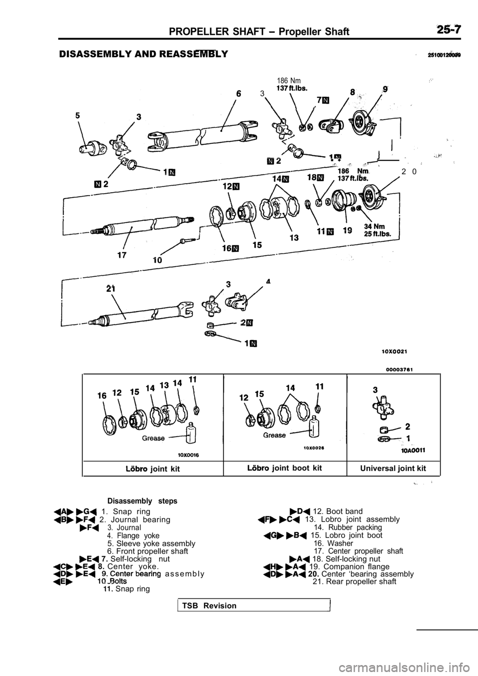
DISASSEMBLY AND REASSEMBLY
186 Nm
3
n u- - -
2 0
21
joint kit joint boot kitUniversal joint kit
Disassembly steps
1. Snap ring
2. Journal bearing3.Journal
4.Flange yoke5. Sleeve yoke assembly
6. Front propeller shaft
7. Self-locking nut 8. Center yoke. a s s e m b l y
Snap ring
12. Boot band 13. Lobro joint assembly
14. Rubber packing 15. Lobro joint boot
16. Washer
17. Center propeller shaft
18. Self-locking nut 19. Companion flange 20. Center ‘bearing assembly
21. Rear propeller shaft
TSB Revision
Page 1498 of 2103
25-8PROPELLER SHAFT ‘Propeller
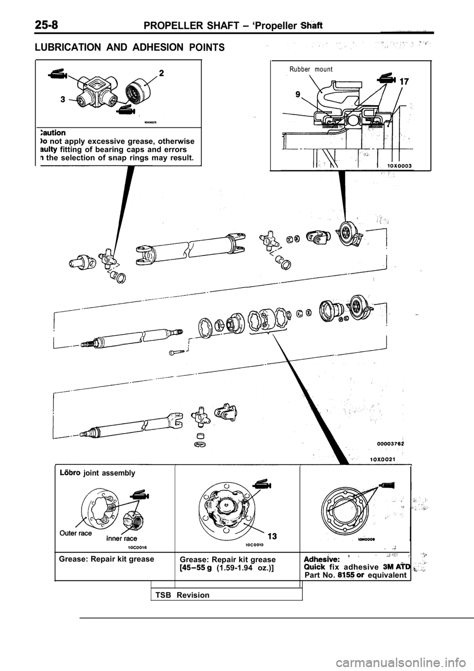
LUBRICATION AND ADHESIONPOINTS
not apply excessive grease, otherwise
fitting of bearing caps and errors
the selection of snap rings may result.
Rubber mount
joint assembly
Grease: Repair kit greaseGrease: Repair kit grease
(1.59-1.94 oz.)]
,
fix adhesive
Part No. equivalent
TSB Revision
Page 1499 of 2103
PROPELLER SHAFT Propeller, Shaft
J o u r n a l
I
Mating
Cen t er
\I
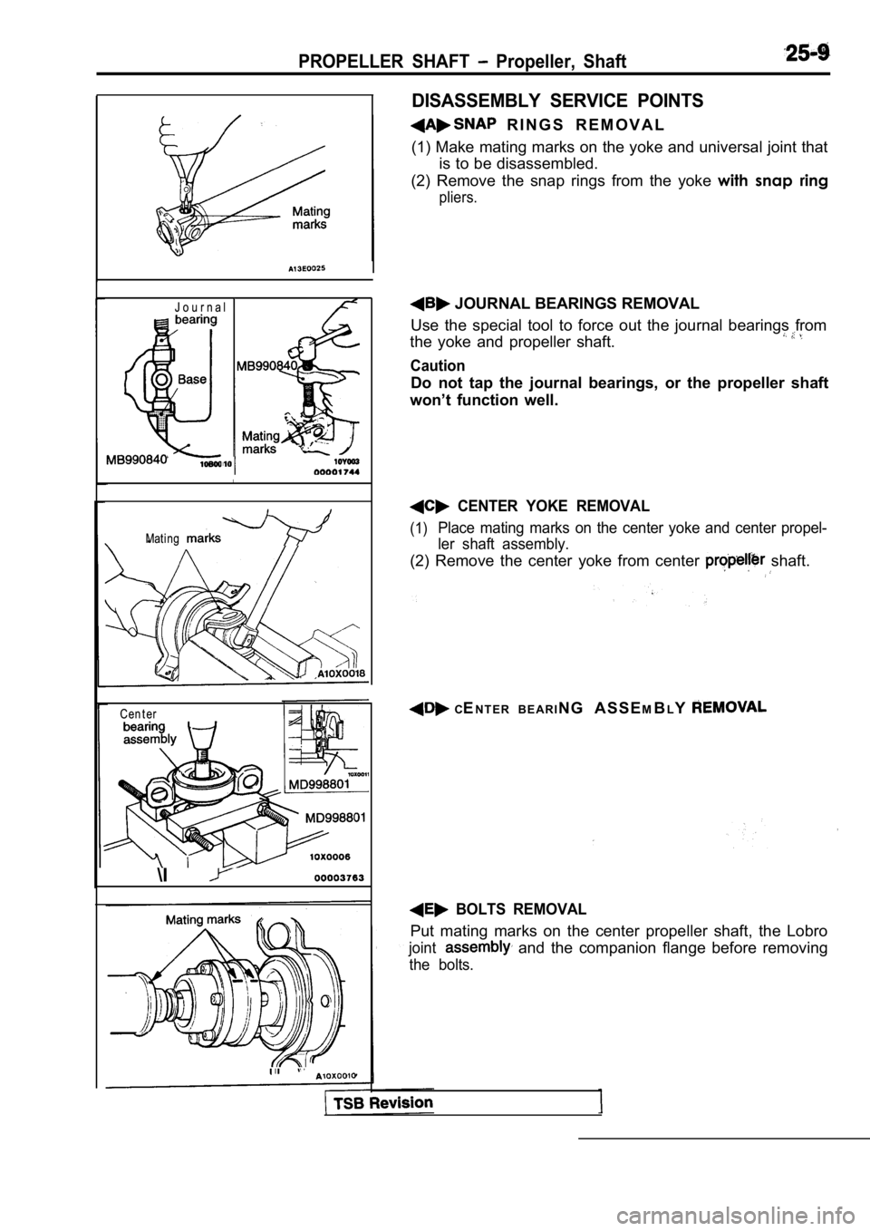
DISASSEMBLY SERVICE POINTS
R I N G S R E M O V A L
(1) Make mating marks on the yoke and universal joi nt that
is to be disassembled.
(2) Remove the snap rings from the yoke with snap ring
pliers.
JOURNAL BEARINGS REMOVAL
Use the special tool to force out the journal beari ngs from
the yoke and propeller shaft.
Caution
Do not tap the journal bearings, or the propeller s haft
won’t function well.
CENTER YOKE REMOVAL
(1)Place mating marks on the center yoke and center pr opel-
ler shaft assembly.
(2) Remove the center yoke from center shaft.
C EN T E R B E A R I N G A S S E MB LY
BOLTS REMOVAL
Put mating marks on the center propeller shaft, the Lobro
joint and the companion flange before removing
the bolts.
Page 1500 of 2103
PROPELLER SHAFT Shaft
Mat i n g m ar k s
Inner race
Cag e
Cag e
Lbbro ioint
Plastic
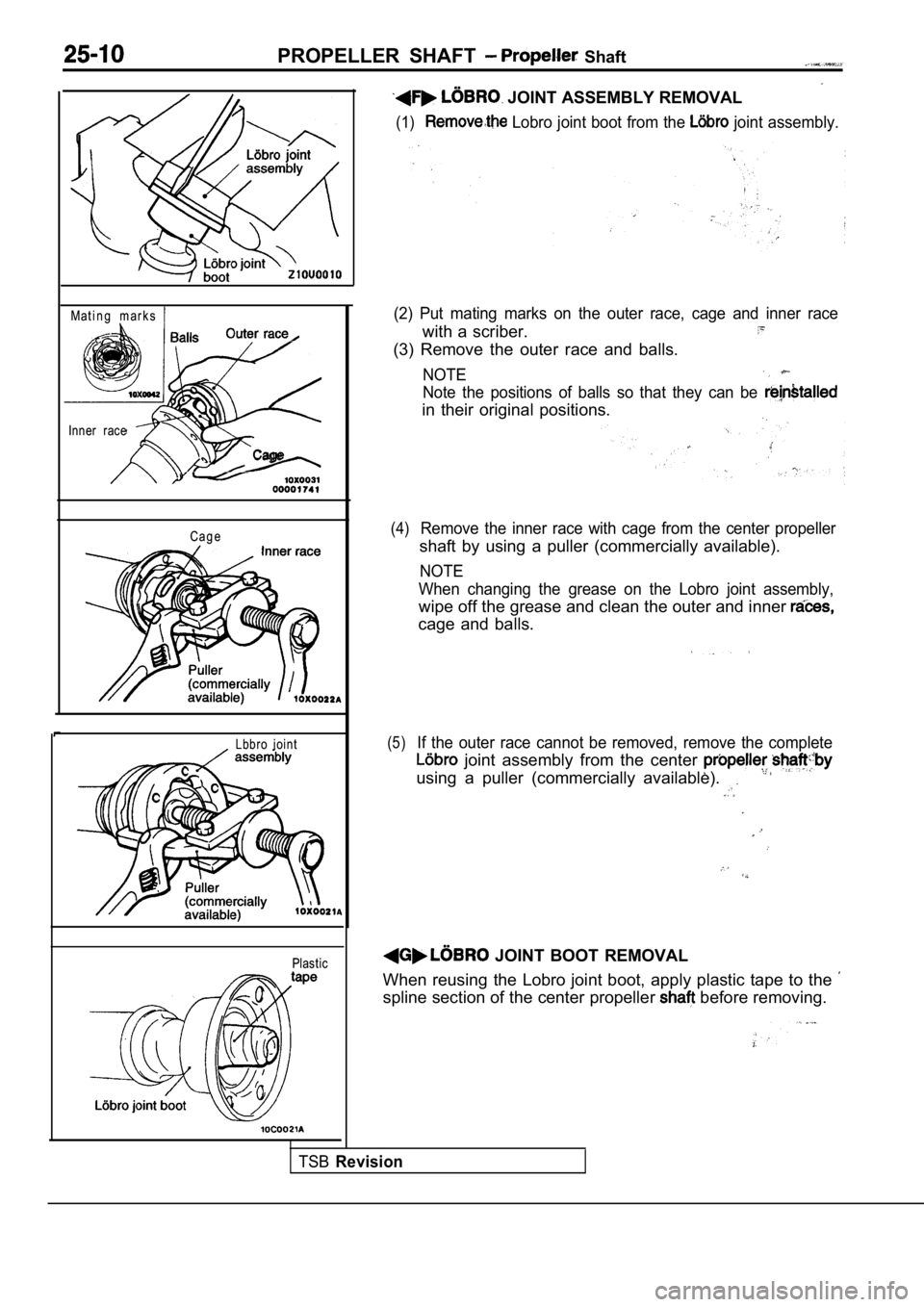
JOINT ASSEMBLY REMOVAL
(1) Lobro joint boot from the joint assembly.
(2) Put mating marks on the outer race, cage and in ner race
with a scriber.
(3) Remove the outer race and balls.
NOTE
Note the positions of balls so that they can be
in their original positions.
(4)Remove the inner race with cage from the center propeller
shaft by using a puller (commercially available).
NOTE
When changing the grease on the Lobro joint assembl y,
wipe off the grease and clean the outer and inner
cage and balls.
(5)If the outer race cannot be removed, remove the complete
joint assembly from the center
using a puller (commercially available).
JOINT BOOT REMOVAL
When reusing the Lobro joint boot, apply plastic ta pe to the
spline section of the center propeller before removing.
TSBRevision
Trending: check transmission fluid, fuel, battery replacement, tires, steering, height, low beam
