MITSUBISHI SPYDER 1990 Service Repair Manual
Manufacturer: MITSUBISHI, Model Year: 1990, Model line: SPYDER, Model: MITSUBISHI SPYDER 1990Pages: 2103, PDF Size: 68.98 MB
Page 1531 of 2103
F R O N T A X L E __ ,
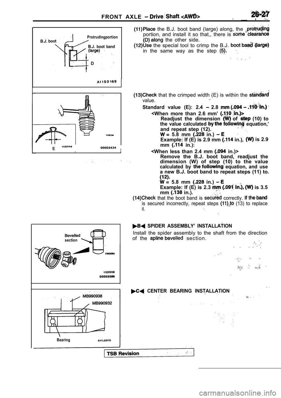
Protrudingportion
B.J. boot band
the B.J. boot band (large) along, the
portion, and install it so that,, there is
the other side.
the special tool to crimp the B.J.
in the same way as the step
I
section
Bearing
that the crimped width (E) is within the
value.
Standard value (E): 2.4 2.8
the value calculated equation,’
and repeat step (12).
5.8 mm in.)
Example: If (E) is 2.9 mm in.), is 2.9
mm
in.):
Remove the B.J. boot band, readjust the
dimension (W) of step (10) to the value
calculated by equation, and use
a new B.J. boot band to repeat steps (11) to.
5.8 mm in.)
Example: If (E) is 2.3 is 3.5
mm
in.).
that the boot band is correctly.
is secured incorrectly, repeat steps (13) to replace
it.
SPIDER ASSEMBLY’ INSTALLATION
Install the spider assembly to the shaft from the d irection
of the
s e c t i o n .
CENTER BEARING INSTALLATION
Page 1532 of 2103
FRONT AXLE Drive. Shaft
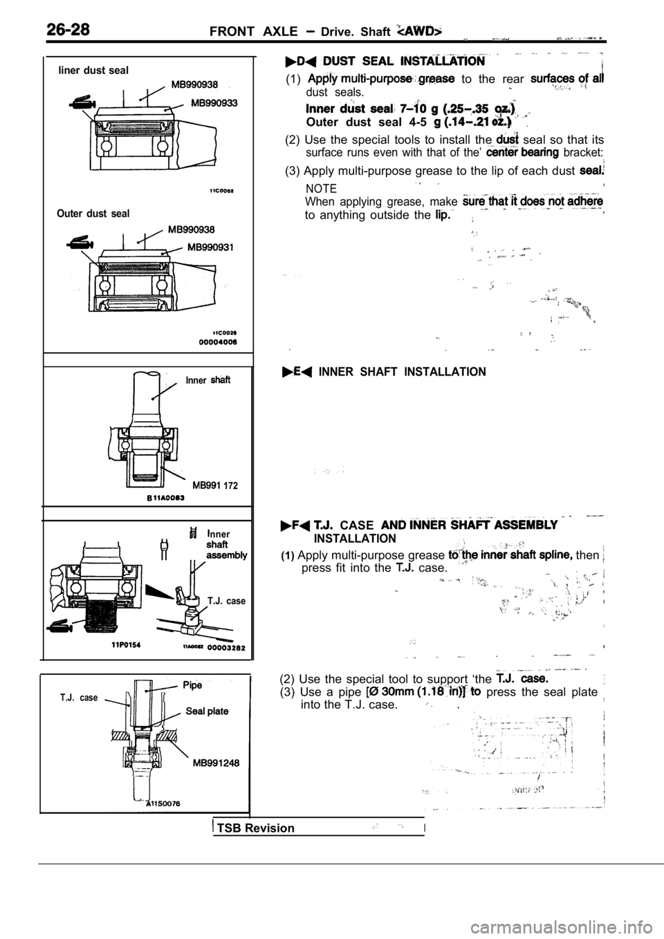
liner dust seal
Outer dust seal
Inner
172
nner
T.J. case
T.J. case
(1) to the rear
dust seals.
Outer dust seal 4-5
(2) Use the special tools to install the seal so that its
surface runs even with that of the’ bracket:
(3) Apply multi-purpose grease to the lip of each dust
NOTE
When applying grease, make
to anything outside the
. . . .
INNER SHAFT INSTALLATION
CASE
INSTALLATION
(1)Apply multi-purpose grease then
press fit into the case.
,
(2) Use the special tool to support ‘the
(3) Use a pipe press the seal plate
into the T.J. case. .
TSB RevisionI
Page 1533 of 2103
FRONT AXLE Drive Shaft
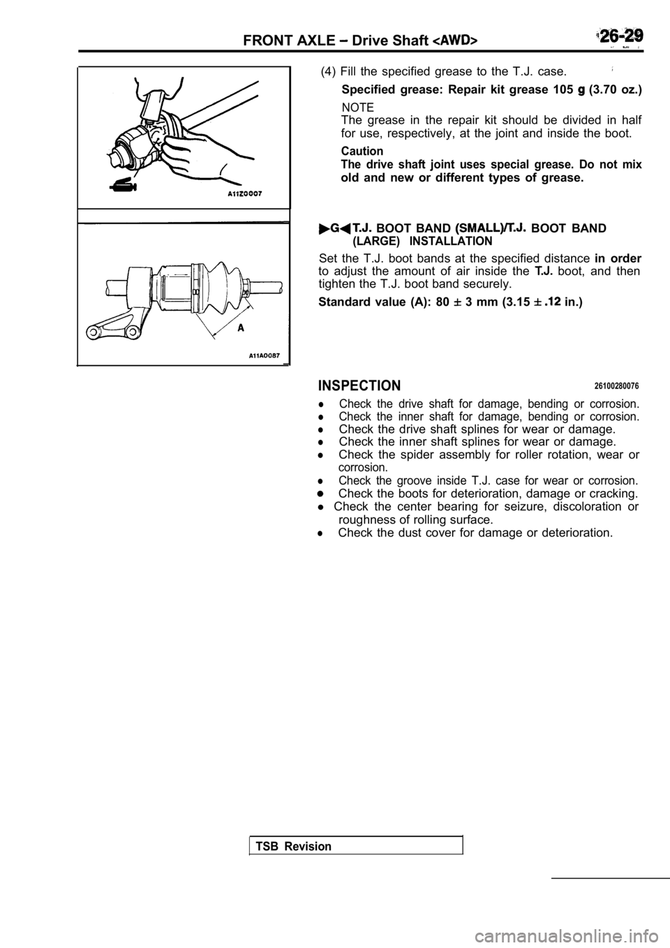
(4) Fill the specified grease to the T.J. case.
Specified grease: Repair kit grease 105 (3.70 oz.)
NOTE
The grease in the repair kit should be divided in half
for use, respectively, at the joint and inside the boot.
Caution
The drive shaft joint uses special grease. Do not m ix
old and new or different types of grease.
BOOT BAND BOOT BAND
(LARGE) INSTALLATION
Set the T.J. boot bands at the specified distance in order
to adjust the amount of air inside the
boot, and then
tighten the T.J. boot band securely.
Standard value (A): 80
3 mm (3.15 in.)
INSPECTION26100280076
lCheck the drive shaft for damage, bending or corros ion.
lCheck the inner shaft for damage, bending or corros ion.
lCheck the drive shaft splines for wear or damage.
lCheck the inner shaft splines for wear or damage.
lCheck the spider assembly for roller rotation, wear or
corrosion.
lCheck the groove inside T.J. case for wear or corro sion.
Check the boots for deterioration, damage or cracking.
l Check the center bearing for seizure, discoloration or
roughness of rolling surface.
lCheck the dust cover for damage or deterioration.
TSB Revision
Page 1534 of 2103
.NOTES
,
Page 1535 of 2103
R E A R A X L E
CONTENTS
DIFFERENTIAL CARRIER. . . . . . . . . . . . . . .29
DRIVE SHAFT
. . . . . . . . . . . . . . . . . . . . . . . . . .21
GENERAL INFORMATION. . . . . . . . . . . . . . . .9
KNUCKLE
. . . . . . . . . . . . . . . . . . . . . . . . . . . . . .20
LSD CASE ASSEMBLY . . . . . . . . . . . . . . . . .46
LUBRICANTS. . . . . . . . . . . . . . . . . . . . . . . . . .10
REAR HUB ASSEMBLY. . . . . . . . . . . . . . . . .18
SEALANTS AND ADHESIVES . . . . . . . . . . .10
ON-VEHICLE SERVICE. . . . . . . . . . . . . . . . .16
Differential Carrier Oil Seal Replacement
. . .17
Gear Oil Level Check. . . . . . . . . . . . . . . . . . . .16
Hub Bolt Replacement. . . . . . . . . . . . . . . . . . . .17
Limited Slip Differenital Condition Check(VCU type). . . . . . . . . . . . . . . . . . . . . . . . . . . . . .17
Rear Axle Total Backlash Check
. . . . . . . . . .16
Wheel Bearing End Play Check. . . . . . . . . . .17
SERVICE SPECIFICATIONS. . . . . . . . . . . . .10
SPECIAL TOOLS. . . . . . . . . . . . . . . . . . . . . . .11
TROUBLESHOOTING. . . . . . . . . . . . . . . . . . .14
GENERAL INFORMATION . . . . . . . . . . . . . . . .
2
KNUCKLE. . . . . . . . . . . . . . . . . . . . . . . . . . . . . . .7
REAR HUB ASSEMBLY . . . . . . . . . . . . . . . . . .
5
ON-VEHICLE SERVICE. . . . . . . . . . . . . . . . . .3
Hub Bolt Replacement. . . . . . . . . . . . . . . .
. . . . .4
Rear Hub Rotary-Sliding Resistance Check
. . . . . . . . . . . . . . . . . . . . . . . . . .
. . . . . . . . . . . . . . . .3
Wheel Bearing End Play Check . . . . . . . . . . .
. 3
SERVICE SPECIFICATIONS’ . . . . . . . . . . . . 2
SPECIAL TOOLS . . . . . . . . . . . . . . . . . . . . . . . . 2
TROUBLESHOOTING. . . . . . . . . . . . . . . . . . 3
Page 1536 of 2103
General Information/Service Specifications/
REAR AXLE Special Tools
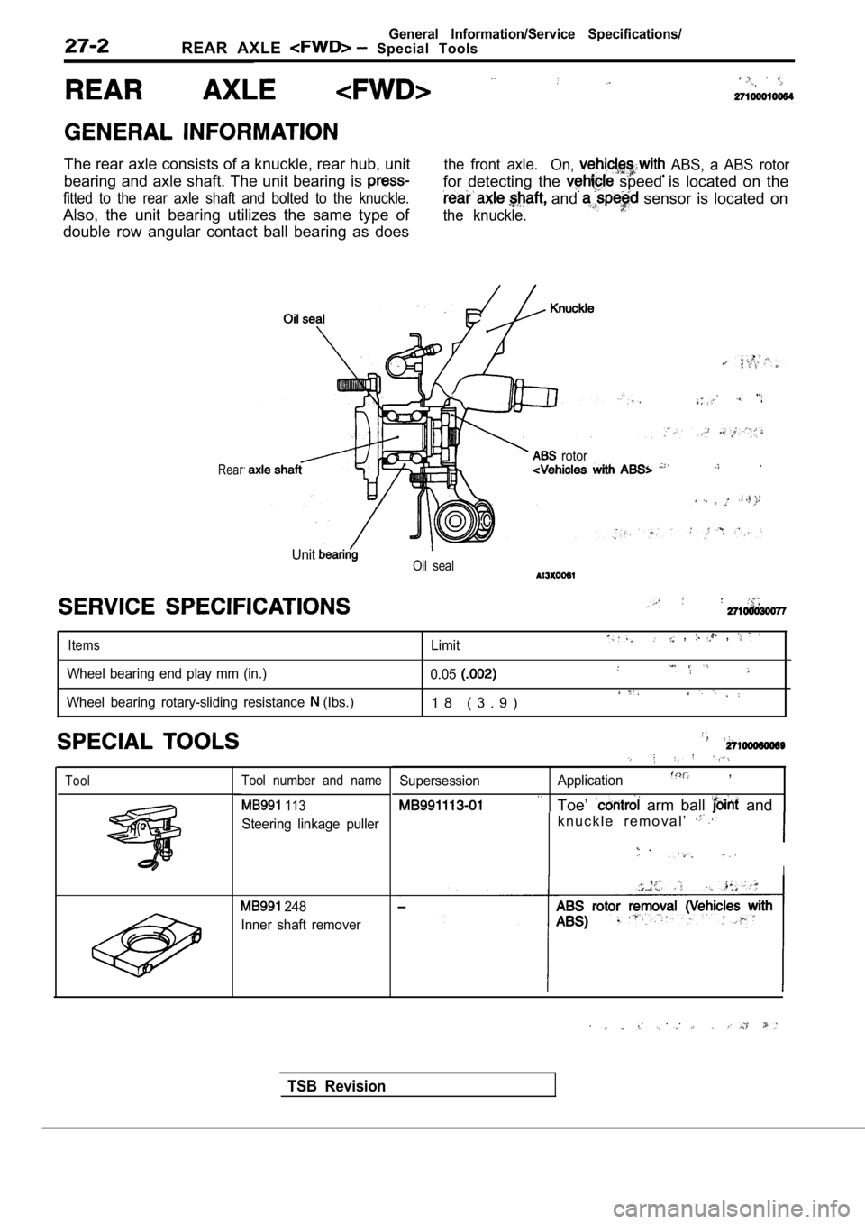
The rear axle consists of a knuckle, rear hub, unit
bearing and axle shaft. The unit bearing is
fitted to the rear axle shaft and bolted to the knuckle.
Also, the unit bearing utilizes the same type of
double row angular contact ball bearing as does
the front axle.
On, ABS, a ABS rotor
for detecting the speed is located on the
and sensor is located on
the knuckle.
Rear rotor
UnitOil seal
Items
Wheel bearing end play mm (in.)
Wheel bearing rotary-sliding resistance
(Ibs.) Limit
, ,
0.05
1 8 ( 3 . 9 )
ToolTool number and name
113
Steering linkage puller
248
Inner shaft remover
Supersession Application,
Toe’ arm ball and
k n u c k l e r e m o v a l ’
.
I
. .
TSB Revision
Page 1537 of 2103
REAR AXLE . .
Symptom
Abnormal
Probable cause
Loose wheel nuts
Damaged or worn wheel
Bentordistorted brake discs
Remedy
Tighten Replace
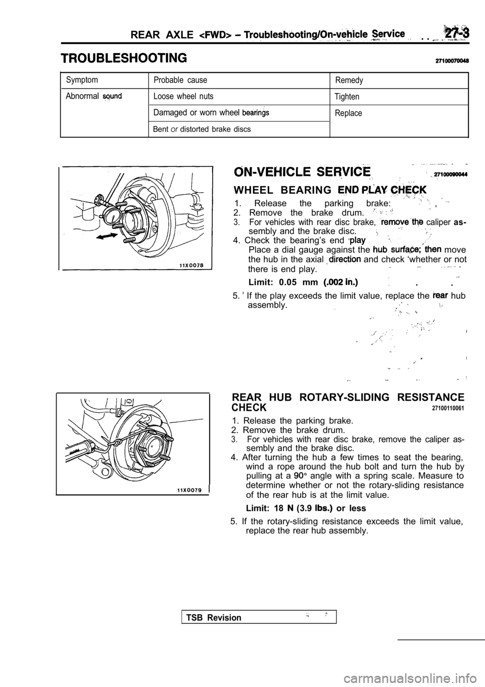
WHEEL BEARING
1. Release the parking brake: ,
2. Remove the brake drum.
3.For vehicles with rear disc brake, caliper as-
sembly and the brake disc.
4. Check the bearing’s end
Place a dial gauge against the move
the hub in the axial
and check ‘whether or not
there is end play. .
.
Limit: 0.05 mm .
5.
If the play exceeds the limit value, replace the hub
assembly.
.
REAR HUB ROTARY-SLIDING RESISTANCE
CHECK27100110061
1. Release the parking brake.
2. Remove the brake drum.
3.For vehicles with rear disc brake, remove the calip er as-
sembly and the brake disc.
4. After turning the hub a few times to seat the be aring,
wind a rope around the hub bolt and turn the hub by pulling at a
angle with a spring scale. Measure to
determine whether or not the rotary-sliding resista nce
of the rear hub is at the limit value.
Limit: 18
(3.9 or less
5. If the rotary-sliding resistance exceeds the lim it value,
replace the rear hub assembly.
TSB Revision
Page 1538 of 2103
REAR AXLE On-vehicle Service
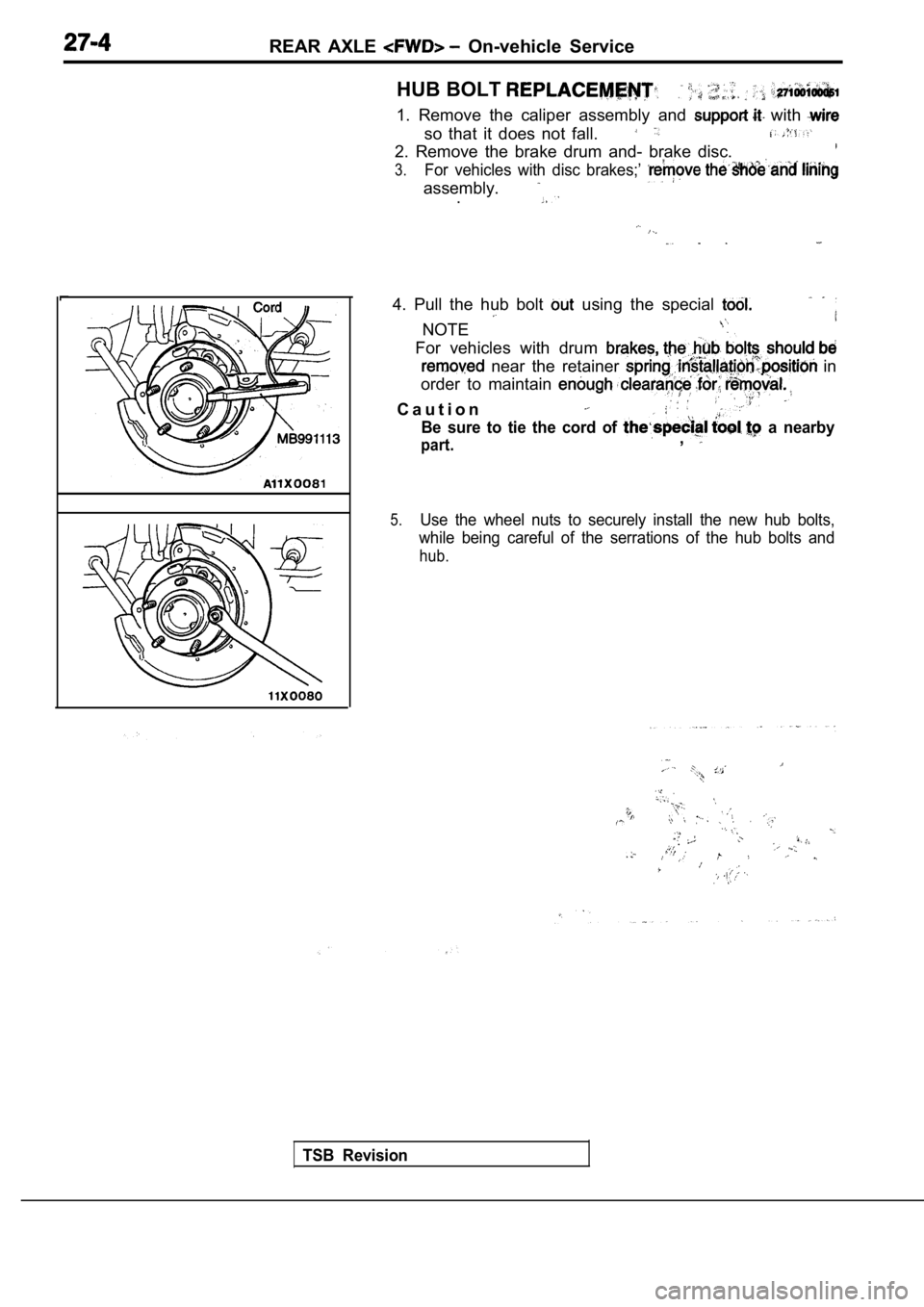
HUB BOLT
1. Remove the caliper assembly and with
so that it does not fall.
2. Remove the brake drum and- brake disc.
3.For vehicles with disc brakes;’
assembly..
4. Pull the hub bolt using the special
NOTE
For vehicles with drum
near the retainer in
order to maintain
C a u t i o n
Be sure to tie the cord of a nearby
part.,
5.Use the wheel nuts to securely install the new hub bolts,
while being careful of the serrations of the hub bo lts and
hub.
TSB Revision
.
,
,
,
Page 1539 of 2103
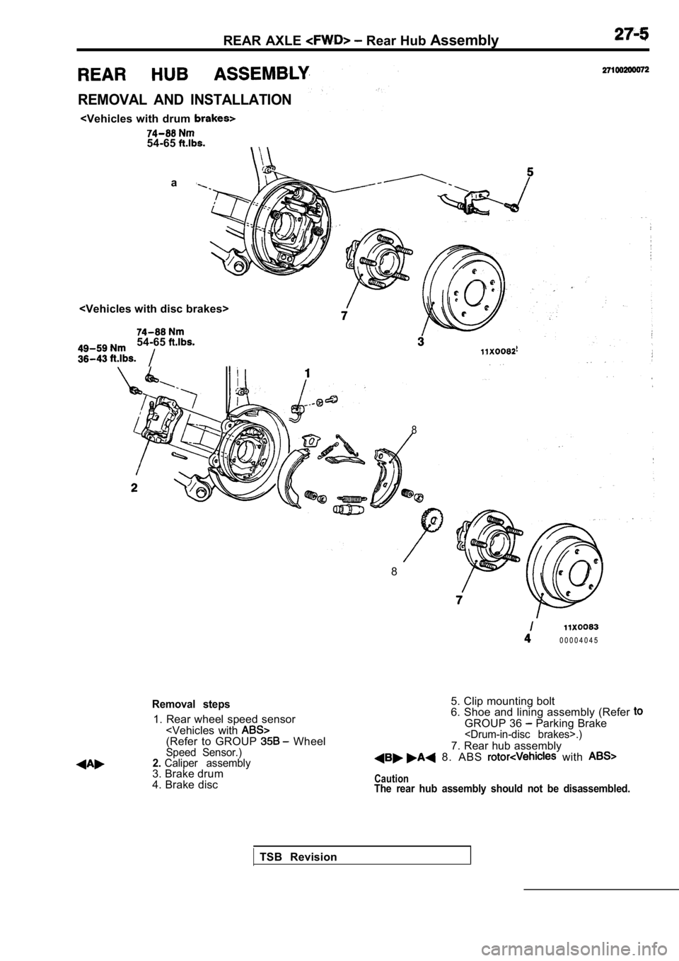
REAR AXLE Rear Hub Assembly
REMOVAL AND INSTALLATION
a
54-65
8
8
0 0 0 0 4 0 4 5
Removal steps
1. Rear wheel speed sensor
4. Brake disc 5. Clip mounting bolt
6. Shoe and lining assembly (Refer
GROUP 36 Parking Brake
7. Rear hub assembly 8. ABS with
CautionThe rear hub assembly should not be disassembled.
TSB Revision
Page 1540 of 2103
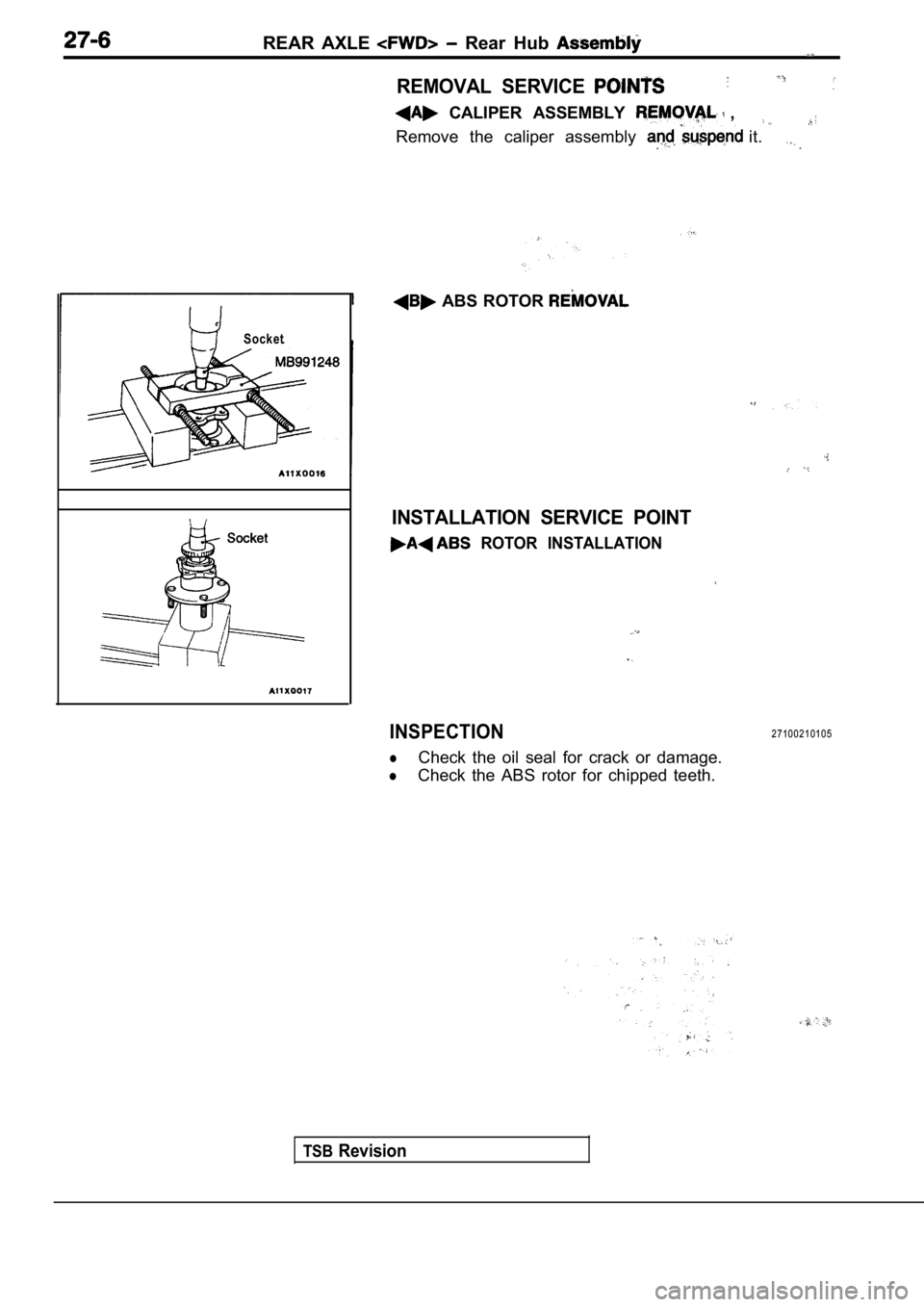
REAR AXLE Rear Hub
REMOVAL SERVICE
CALIPER ASSEMBLY ,
Remove the caliper assembly it.
Socket
ABS ROTOR
TSBRevision
INSTALLATION SERVICE POINT
ROTOR INSTALLATION
INSPECTION
lCheck the oil seal for crack or damage.
lCheck the ABS rotor for chipped teeth.
27100210105