MITSUBISHI SPYDER 1990 Service Repair Manual
Manufacturer: MITSUBISHI, Model Year: 1990, Model line: SPYDER, Model: MITSUBISHI SPYDER 1990Pages: 2103, PDF Size: 68.98 MB
Page 1501 of 2103
S H A F T
Plastic
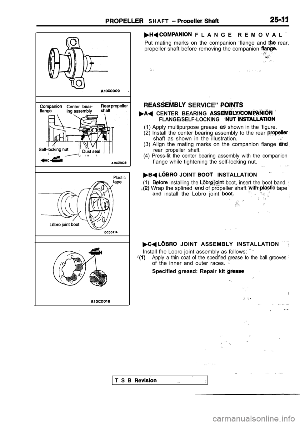
F L A N G E R E M O V A L
Put mating marks on the companion ‘flange and rear,
propeller shaft before removing the companion
SERVICE”
CENTER BEARING
FLANGE/SELF-LOCKING
(1) Apply multipurpose grease shown in the ‘figure.
(2) Install the center bearing assembly to the rear
shaft as shown in the illustration.
(3) Align the mating marks on the companion flange
rear propeller shaft.
(4) Press-fit the center bearing assembly with the companion
flange while tightening the self-locking nut.
JOINT INSTALLATION
(1) installing the boot, insert the boot band.
Wrap the splined of propeller shaft tape
install the Lobro joint ,
JOINT ASSEMBLY INSTALLATION
Install fhe Lobro joint assembly as follows:
Apply a thin coat of the specified grease to the ba ll grooves
of the inner and outer races.
Specified greasd: Repair kit
.
. - -
T S B
Page 1502 of 2103
PROPELLER
BallMating
marks
Rec es s ed end
of inner race
Chamferedend of cage
on outer
race for fitting the Ball
packing
Socket wrench
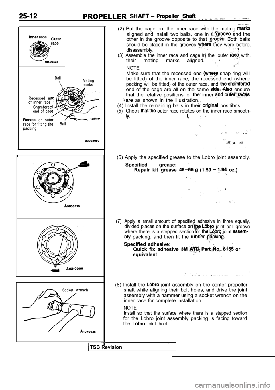
(2) Put the cage on, the inner race with the mating
aligned and install two balls, one in and the
other in the groove opposite to that
Both balls
should be placed in the grooves they were before,
disassembly.
(3) Assemble the inner race and cage the, outer with,
their mating marks aligned.
NOTE
Make sure that the recessed end snap ring will
be fitted) of the inner race, the recessed end (whe re
packing will be fitted) of the outer race, and
end of the cage are all on the same ensure
that the relative positions’ of
inner
as shown in the illustration.,
(4) Install the remaining balls in their
positibns.
(5)Check outer race rotates on the inner race smooth-
I,
,
. . . .
(6) Apply the specified grease to the Lobro joint a ssembly.
Specified grease:
Repair kit grease (1.59 oz.)
. ,
(7) Apply a small amount of specified adhesive in th ree equally,
divided places on the surface joint ball groove
where there is a stepped section or
joint
packing, and then fit the
Specified adhesive:
Quick fix adhesive or
equivalent
(8) Install the joint assembly on the center propeller
shaft while aligning their bolt holes, and drive th e joint
assembly with a hammer using a socket wrench on the inner race for complete installation.
NOTE
Install so that the surface where there is a steppe d section
for the Lobro joint assembly packing is facing towa rd
the
joint boot.
TSB Revision
Page 1503 of 2103
P R O P E L L E R S H A F T Propeller Shaft
Mounting boltsI
band clip position I
Center bearing assembly
Journal
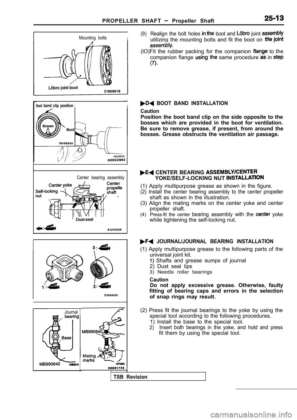
(9)Realign the bolt holes boot and joint
utilizing the mounting bolts and fit the boot on
(lO)Fit the rubber packing for the companion to the
companion flange
same procedure in
BOOT BAND INSTALLATION
Caution
Position the boot band clip on the side opposite to the
bosses which are provided in the boot for ventilati on.
Be sure to remove grease, if present, from around t he
bosses. Grease obstructs the ventilation air passag e.
CENTER BEARING
YOKE/SELF-LOCKING NUT
(1) Apply multipurpose grease as shown in the figure.
(2) Install the center bearing assembly to the center propeller
shaft as shown in the illustration.
(3) Align the mating marks on the center yoke and c enter
propeller shaft.
(4) Press-fit the center bearing assembly with the yoke
while tightening the self-locking nut.
JOURNAL/JOURNAL BEARING INSTALLATION
(1) Apply multipurpose grease to the following parts of the
universal joint kit.
Shafts and grease sumps of journal
2) Dust seal lips
3) Needle roller bearings
Caution
Do not apply excessive grease. Otherwise, faulty
fitting of bearing caps and errors in the selection
of snap rings may result.
(2) Press fit the journal bearings to the yoke by u sing the
special tool according to the following procedures.
1) Install the base to the special tool.
2)Insert both bearings in the yoke, and hold and pres s
fit them by using the special tool.
TSB Revision
Page 1504 of 2103
PROPELLER SHAFT Propeller Shaft
Balls
SNAP RINGS
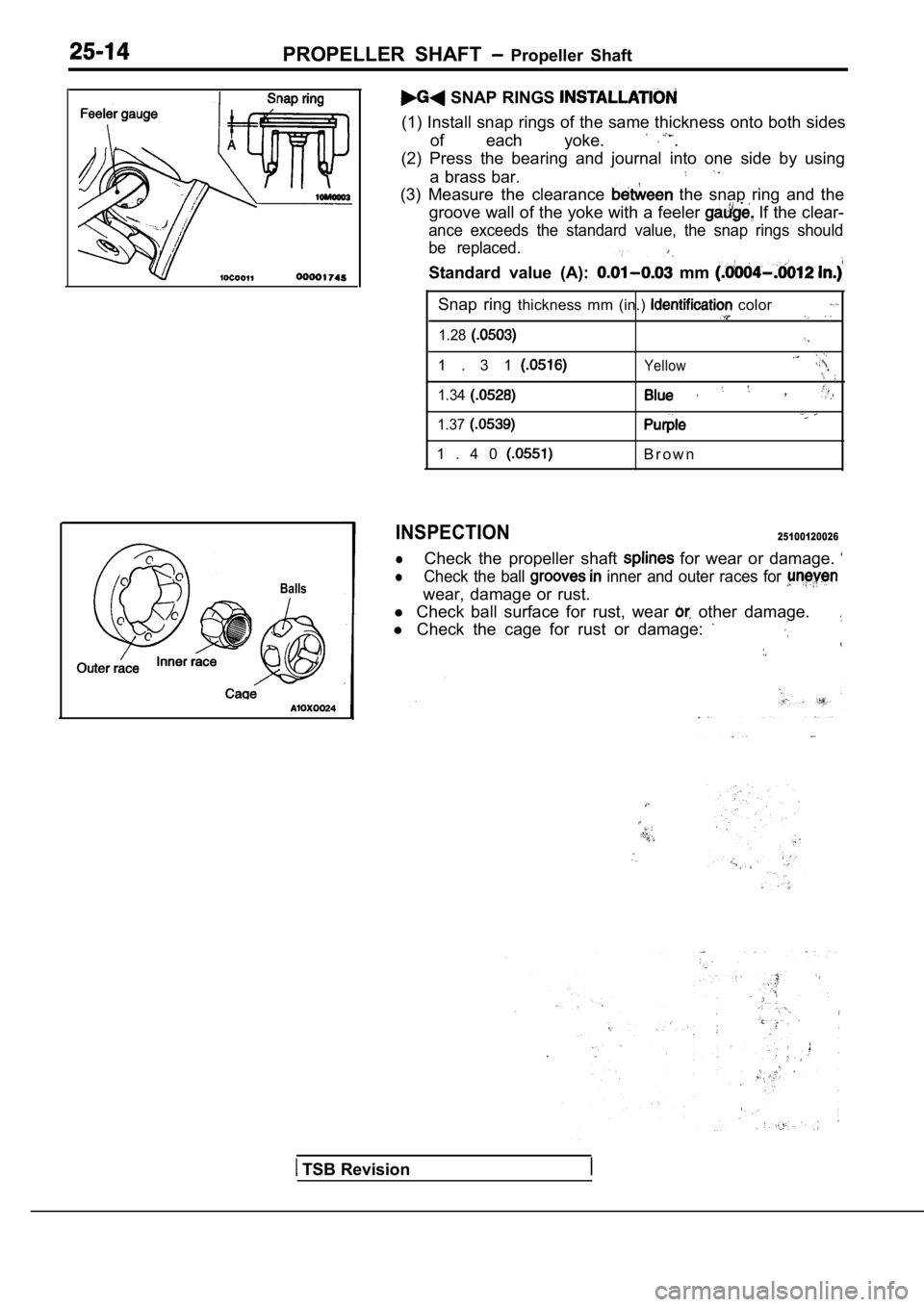
(1) Install snap rings of the same thickness onto both sides
of each yoke. .
(2) Press the bearing and journal into one side by using
a brass bar.
(3) Measure the clearance the snap ring and the
groove wall of the yoke with a feeler
If the clear-
ance exceeds the standard value, the snap rings sho uld
be replaced.
Standard value (A): mm
Snap ring thickness mm (in.) color
1.28
1 . 3 1Yellow
1.34 ,
1.37
1 . 4 0B r o w n
INSPECTION25100120026
l
lCheck the propeller shaft for wear or damage.
Check the ball inner and outer races for
wear, damage or rust.
l Check ball surface for rust, wear
other damage.
l Check the cage for rust or damage:
TSB Revision
Page 1505 of 2103
FRONT AXLE
CONTENTS
DRIVE SHAFT 10ON-VEHICLE SERVICE. . . . . . . . . . . . . . . . . . . . .5. . . . . . . . . . . . . . . . . . . .Hub
Replacement. . . . . . . . . . . . . . . . . . . . . . .5
DRIVE SHAFT . . . . . . . . . . . . . . . . . . . .19Wheel Bearing End Play Check . . . . . . . . . . . . . . .5
FRONT HUB ASSEMBLY. . . . . . . . . . . . . . . . . . .6SERVICE SPECIFICATIONS. . . . . . . . . . . . . . . . .2
GENERAL INFORMATION. . . . . . . . . . . . . . . . . .2SPECIAL TOOLS. . . . . . . . . . . . . . . . . . . . . . . . . . .3
KNUCKLE. . . . . . . . . . . . . . . . . . . . . . . . . . . . . . . . .8TROUBLESHOOTING. . . . . . . . . . . . . . . . . . . . . . .4
LUBRICANTS. . . . . . . . . . . . . . . . . . . . . . . . . . . . . .2
Page 1506 of 2103
GENERAL INFORMATION
FRONT AXLE General Specification/Lubricants
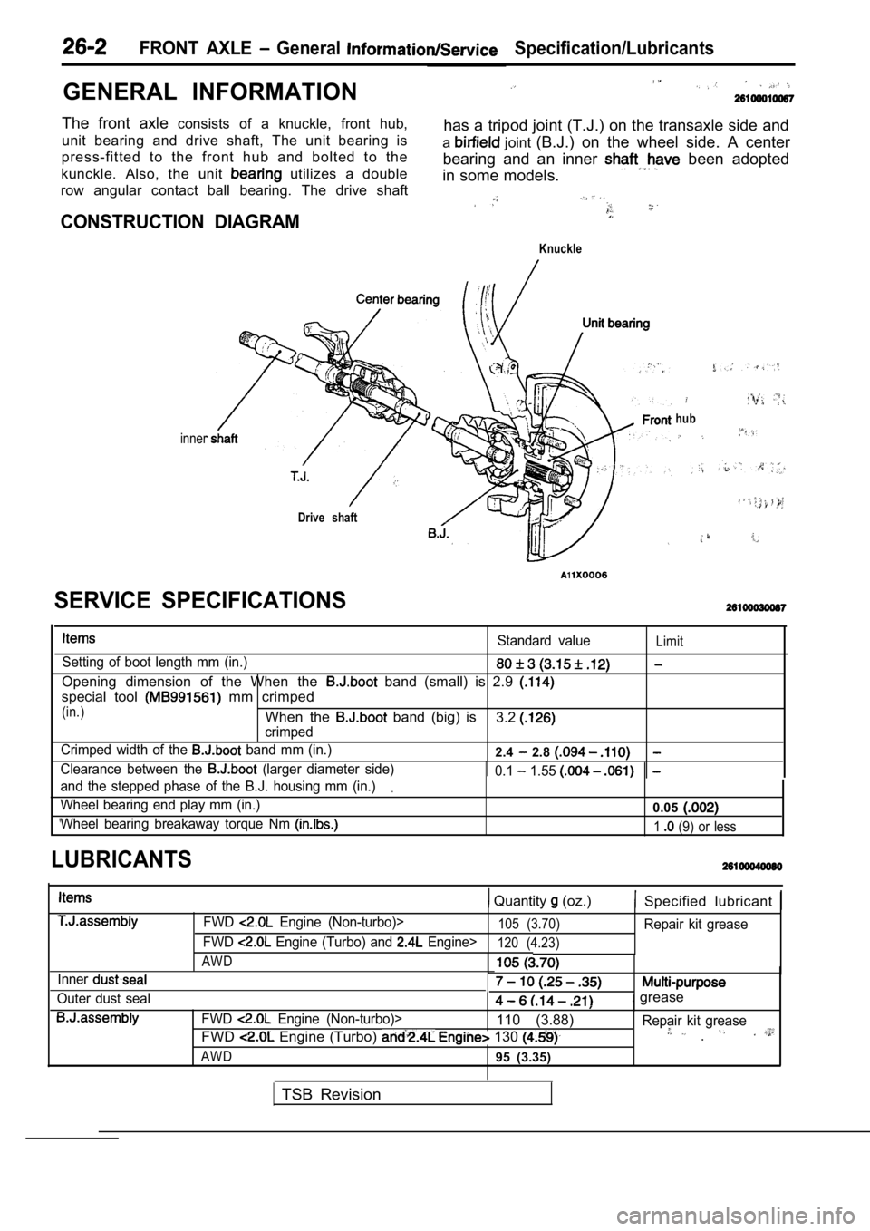
The front axle consists of a knuckle, front hub,
unit bearing and drive shaft, The unit bearing is has a tripod joint (T.J.) on the transaxle side and
press-fitted to the front hub and bolted to the a
joint
(B.J.) on the wheel side. A center
kunckle. Also, the unit
utilizes a double bearing and an inner been adopted
in some models.
row angular contact ball bearing. The drive shaft
CONSTRUCTION DIAGRAM
Knuckle
inner
Drive shaft
hub
Standard valueLimit
Setting of boot length mm (in.)
Opening dimension of the When the band (small) is 2.9
special tool mm crimped
(in.)When the band (big) is
crimped3.2
Crimped width of the band mm (in.)2.4 2.8
Clearance between the (larger diameter side) 0.1 1.55
and the stepped phase of the B.J. housing mm (in.).
Wheel bearing end play mm (in.)0.05
Wheel bearing breakaway torque Nm 1 (9) or less
SERVICE SPECIFICATIONS
LUBRICANTS
Quantity (oz.) Specified lubricant
Inner
Outer dust sealFWD
Engine (Non-turbo)>105 (3.70)Repair kit grease
FWD
Engine (Turbo) and Engine>120 (4.23)
AWD
. grease
FWD Engine (Non-turbo)>110 (3.88) Repair kit grease
FWD Engine (Turbo) 130 .
AWD95 (3.35)
TSB Revision
Page 1507 of 2103
SPECIAL TOOLS
FRONT AXLE Special , . . .
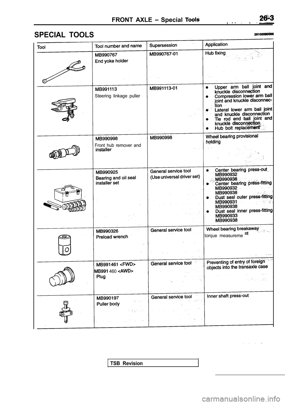
Steering linkage puller
Front hub remover and
torque measureme
460
TSB Revision
Page 1508 of 2103
26-4FRONT AXLE Special
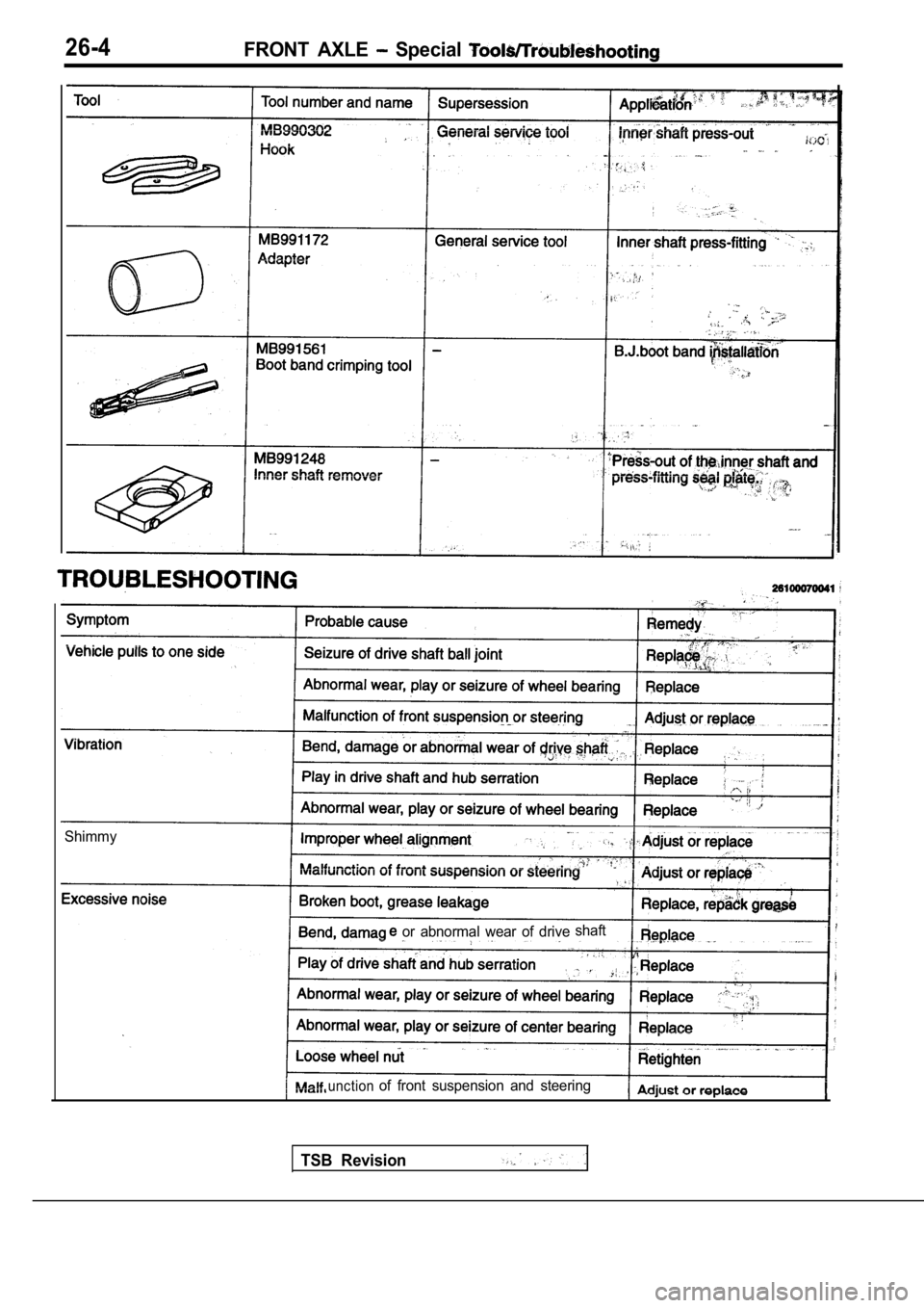
Shimmy
or abnormal wear of driveshaft
unctionof front suspension and steering
TSB Revision
Page 1509 of 2103
I
8990767
ON-VEHICLE SERVICE
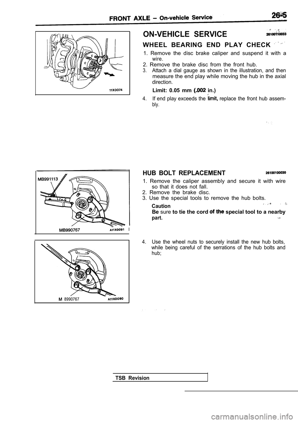
WHEEL BEARING END PLAY CHECK
1. Remove the disc brake caliper and suspend it with a
wire.
2. Remove the brake disc from the front hub.
3.Attach a dial gauge as shown in the illustration, and then
measure the end play while moving the hub in the ax ial
direction.
Limit: 0.05 mm in.)
4.If end play exceeds the replace the front hub assem-
bly.
HUB BOLT REPLACEMENT
1. Remove the caliper assembly and secure it with w ire
so that it does not fall.
2. Remove the brake disc.
3. Use the special tools to remove the hub bolts.
Caution
Be sure to tie the cord special tool to a nearby
part.
4.Use the wheel nuts to securely install the new hub bolts,
while being careful of the serrations of the hub bo lts and
hub;
TSB Revision
Page 1510 of 2103
26-6FRONT AXLE Front
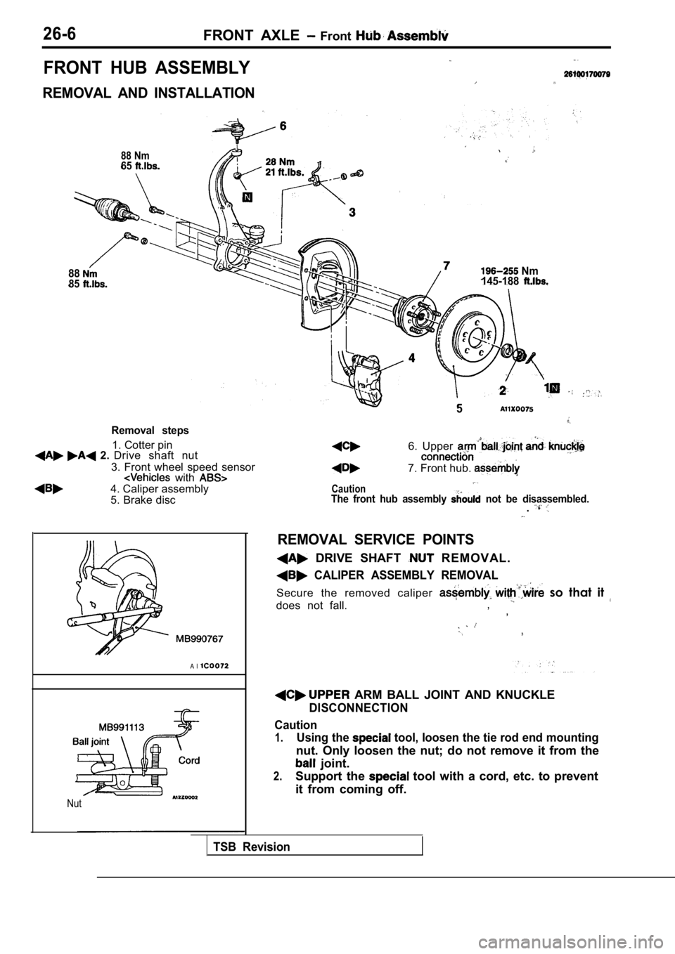
FRONT HUB ASSEMBLY
REMOVAL AND INSTALLATION
88 Nm65
8885
Removal steps
1. Cotter pin 2. Drive shaft nut
3. Front wheel speed sensor
with 4. Caliper assembly
5. Brake disc
A l
Nut
Nm
145-188
5
Caution
6. Upper
7. Front hub.
The front hub assembly not be disassembled..
REMOVAL SERVICE POINTS
DRIVE SHAFT R E M O V A L .
CALIPER ASSEMBLY REMOVAL
Secure the removed caliper so that it
does not fall., ,
ARM BALL JOINT AND KNUCKLE
DISCONNECTION
Caution
1.Using the tool, loosen the tie rod end mounting
nut. Only loosen the nut; do not remove it from the
joint.
2.Support the tool with a cord, etc. to prevent
it from coming off.
TSB Revision