MITSUBISHI SPYDER 1990 Service Repair Manual
Manufacturer: MITSUBISHI, Model Year: 1990, Model line: SPYDER, Model: MITSUBISHI SPYDER 1990Pages: 2103, PDF Size: 68.98 MB
Page 1551 of 2103
REAR AXLE On-vehicle Service
WHEEL BEARING END PLAY CHECK
1. Jack up the vehicle and remove the rear wheel.
2. Release the parking brake.
3.Remove the caliper assembly and the brake disc or b rake
drum.
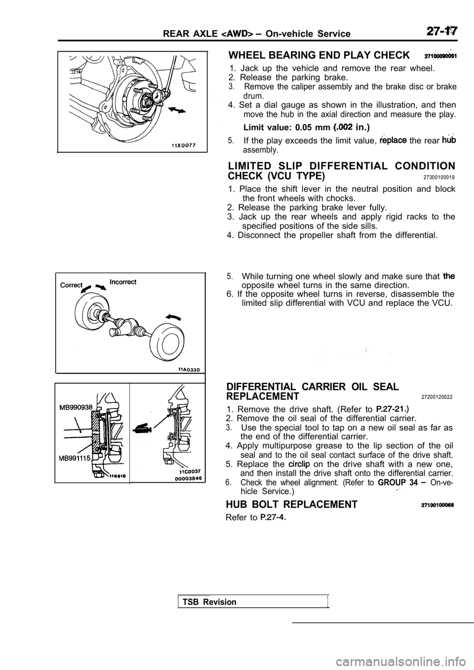
4. Set a dial gauge as shown in the illustration, and then
move the hub in the axial direction and measure the play.
Limit value: 0.05 mm in.)
5.If the play exceeds the limit value, the rear
assembly.
LIMITED SLIP DIFFERENTIAL CONDITION
CHECK (VCU TYPE)27300100019
1. Place the shift lever in the neutral position an d block
the front wheels with chocks.
2. Release the parking brake lever fully.
3. Jack up the rear wheels and apply rigid racks to the
specified positions of the side sills.
4. Disconnect the propeller shaft from the differen tial.
5.While turning one wheel slowly and make sure that
opposite wheel turns in the same direction.
6. If the opposite wheel turns in reverse, disassem ble the
limited slip differential with VCU and replace the VCU.
DIFFERENTIAL CARRIER OIL SEAL
REPLACEMENT27200120022
1. Remove the drive shaft. (Refer to
2. Remove the oil seal of the differential carrier.
3.Use the special tool to tap on a new oil seal as fa r as
the end of the differential carrier.
4. Apply multipurpose grease to the lip section of the oil
seal and to the oil seal contact surface of the drive shaft.
5. Replace the on the drive shaft with a new one,
and then install the drive shaft onto the differential carrier.
6.Check the wheel alignment. (Refer to GROUP 34 On-ve-
hicle Service.)
HUB BOLT REPLACEMENT
Refer to
TSB Revision1
Page 1552 of 2103
REAR AXLE Rear Hub Assembly
REMOVAL AND INSTALLATION
OperationlDrive Shaft Removal (Refer to 1
Nm
7
8
NmNm
11
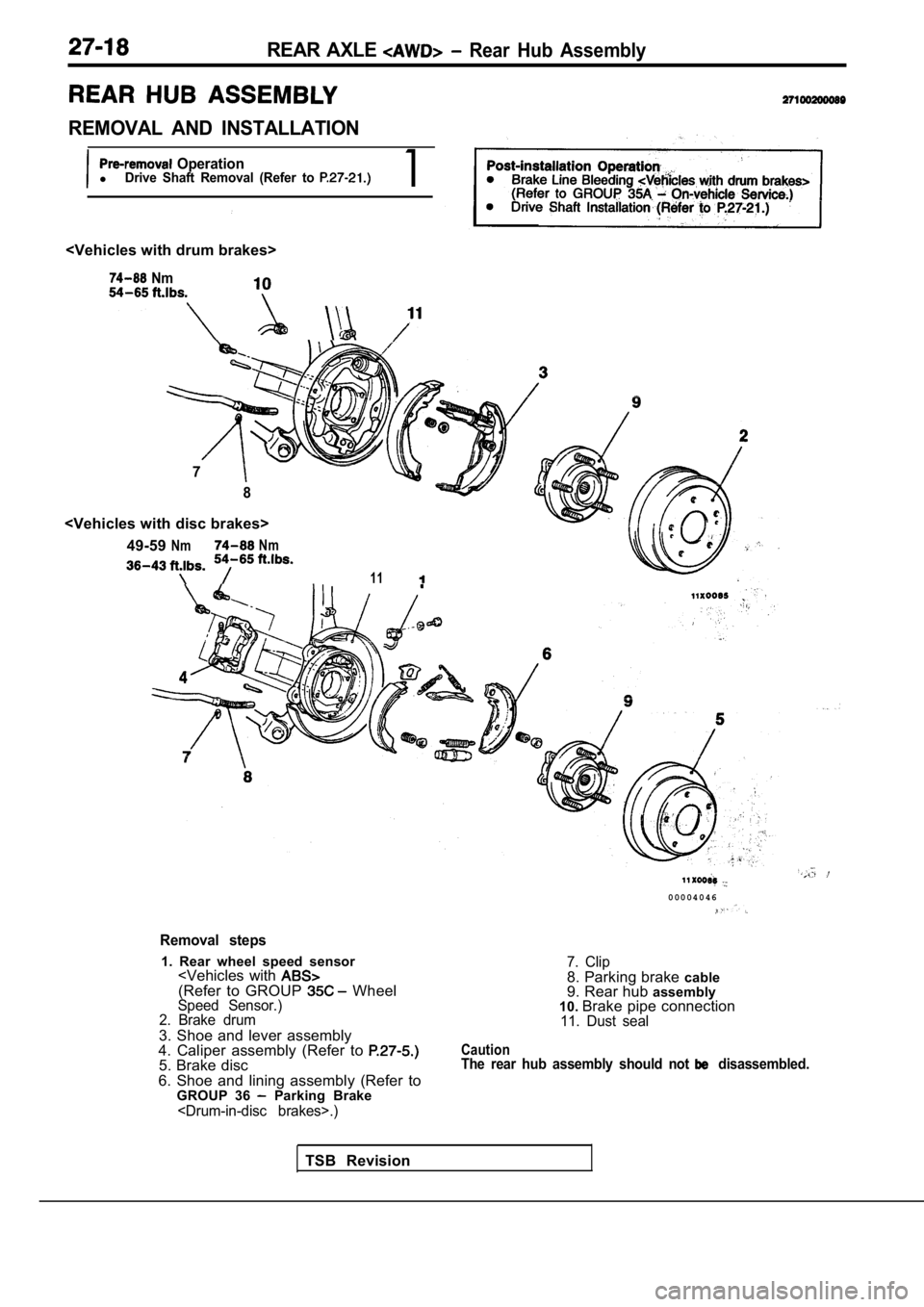
Removal steps
1. Rear wheel speed sensor
2. Brake drum
3. Shoe and lever assembly
4. Caliper assembly (Refer to
5. Brake disc
6. Shoe and lining assembly (Refer to GROUP 36
Parking Brake
0 0 0 0 4 0 4 6
7. Clip8. Parking brake cable
9. Rear hub assembly
10. Brake pipe connection
11. Dust seal
CautionThe rear hub assembly should not disassembled.
TSB Revision
Page 1553 of 2103
REAR AXLE Rear Assembly
INSPECTION
lCheck the oil seal for crack damage.
l Check the rear hub
for wear or damage.
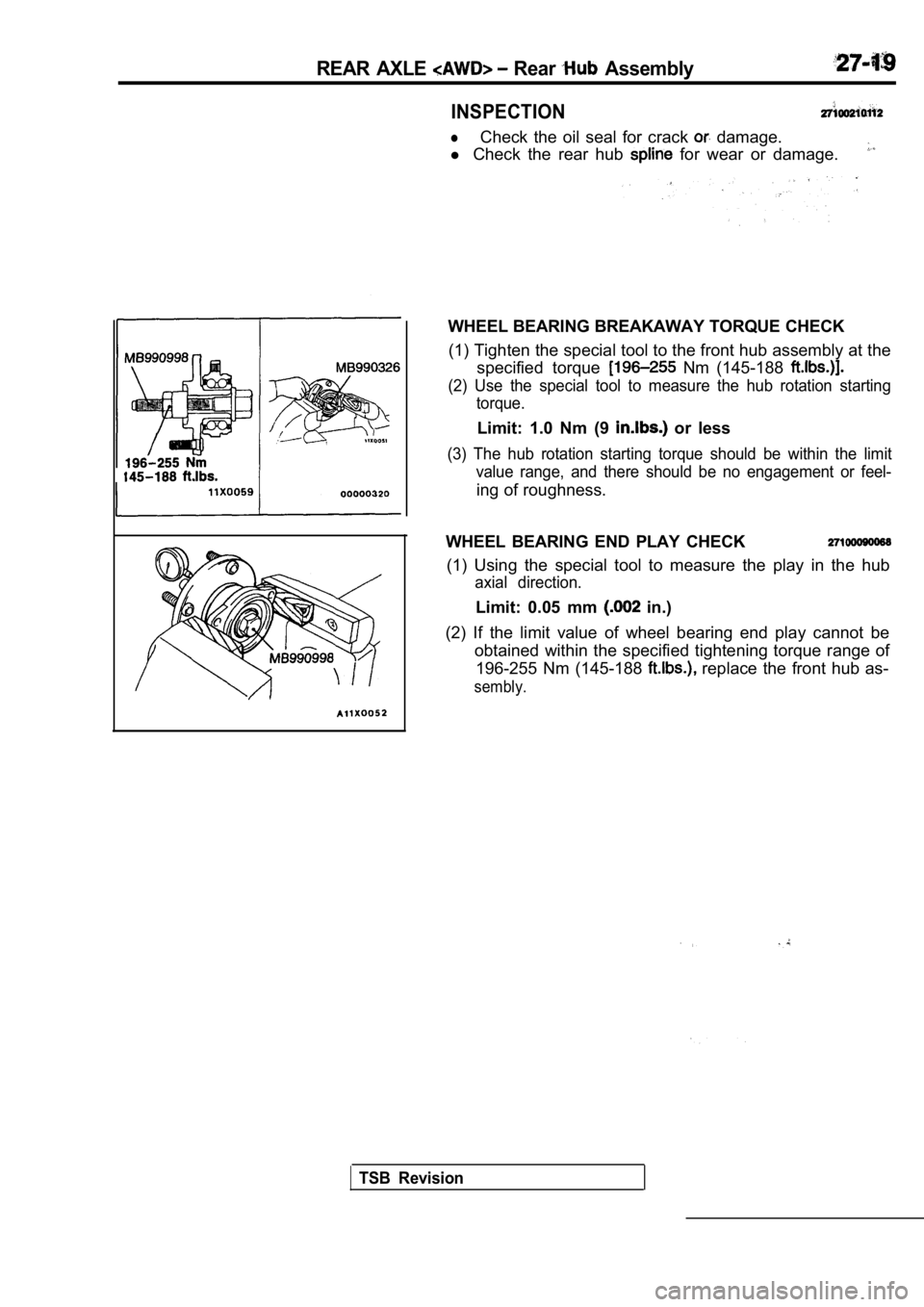
WHEEL BEARING BREAKAWAY TORQUE CHECK
(1) Tighten the special tool to the front hub assem bly at the
specified torque
Nm (145-188
(2) Use the special tool to measure the hub rotatio n starting
torque.
Limit: 1.0 Nm (9 or less
(3) The hub rotation starting torque should be with in the limit
value range, and there should be no engagement or f eel-
ing of roughness.
WHEEL BEARING END PLAY CHECK
(1) Using the special tool to measure the play in t he hub
axial direction.
Limit: 0.05 mm in.)
(2) If the limit value of wheel bearing end play ca nnot be
obtained within the specified tightening torque ran ge of
196-255 Nm (145-188
replace the front hub as-
sembly.
TSB Revision
Page 1554 of 2103
REAR AXLE Knuckle
REMOVAL AND INSTALLATION
II and Post-installation OperationlRear Wheel Speed Sensor Removal and Installation with lRear Hub Assembly Removal and installation(Refer to
98, 71
98
118-13785-99
TSB Revision
9871
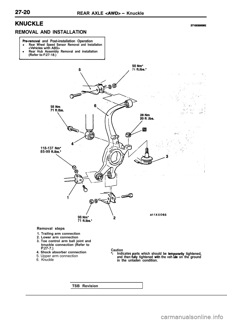
Removal steps
1. Trailing arm connection
2. Lower arm connection
3. Toe control arm ball joint and knuckle connection (Refer to
4. Shock absorber connection
5. Upper arm connection
6. Knuckle
CautionIndicates
and thenarts which should be tightened, tightened the veh on the groundin the unladen condition.
Page 1555 of 2103
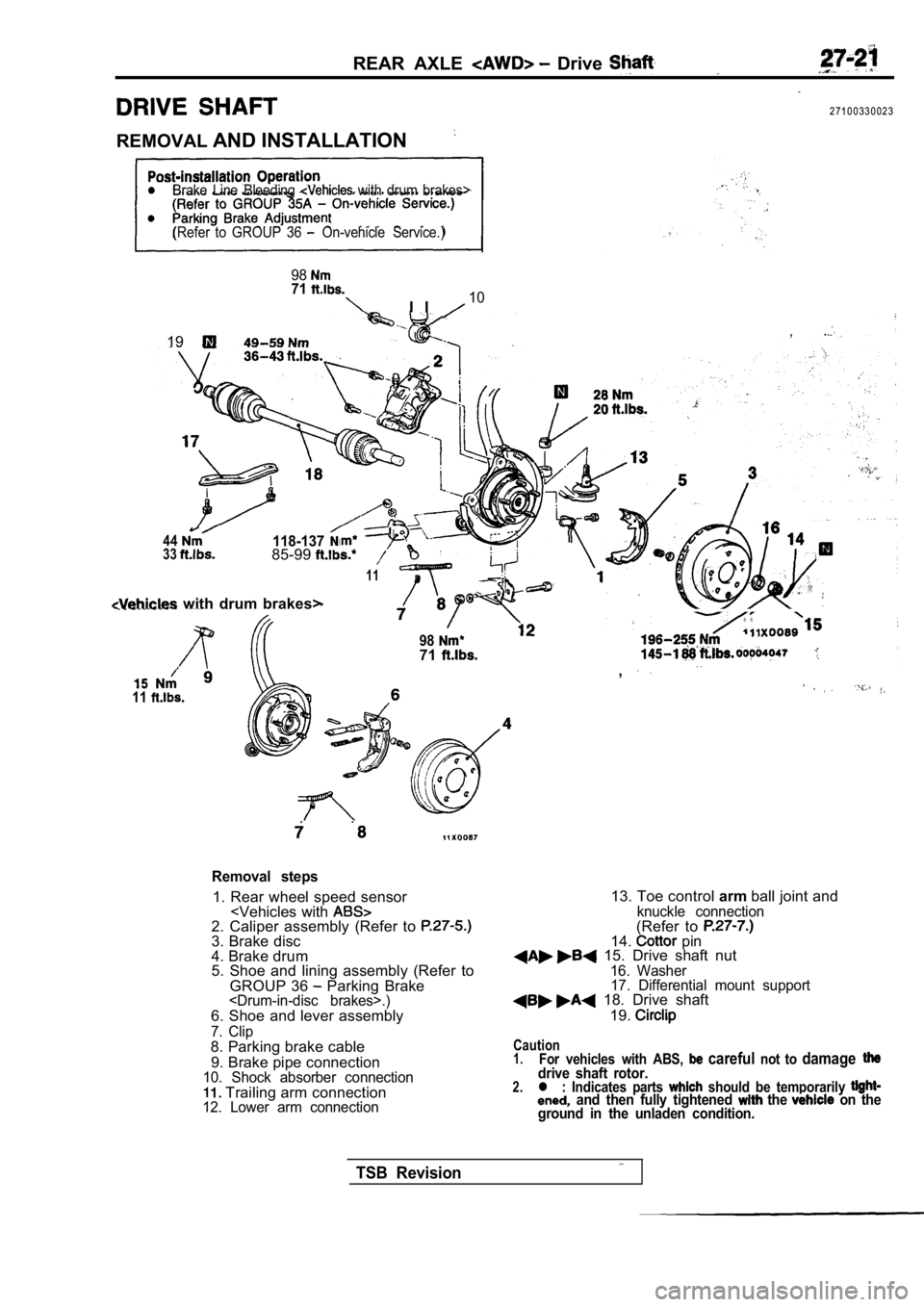
REAR AXLE Drive
2 7 1 0 0 3 3 0 0 2 3
REMOVAL AND INSTALLATION
Brake Line Bleeding with drum brakes>
(Refer to GROUP 36
On-vehicle Service.)
9871
I I10
,19
44118-1373385-99
11
with drum brakes>
11
9871. .,
Removal steps
1. Rear wheel speed sensor
4. Brake drum
5. Shoe and lining assembly (Refer to
GROUP 36
Parking Brake
7. Clip8. Parking brake cable
9. Brake pipe connection
10. Shock absorber connection Trailing arm connection12. Lower arm connection
13. Toe control armball joint andknuckle connection(Refer to 14. pin 15. Drive shaft nut16. Washer
17. Differential mount support
18. Drive shaft
19.
Caution1.For vehicles with ABS, careful not to damagedrive shaft rotor.2.l : Indicates parts should be temporarily and then fully tightened the on the
ground in the unladen condition.
TSB Revision
Page 1556 of 2103
REAR AXLE Shaft
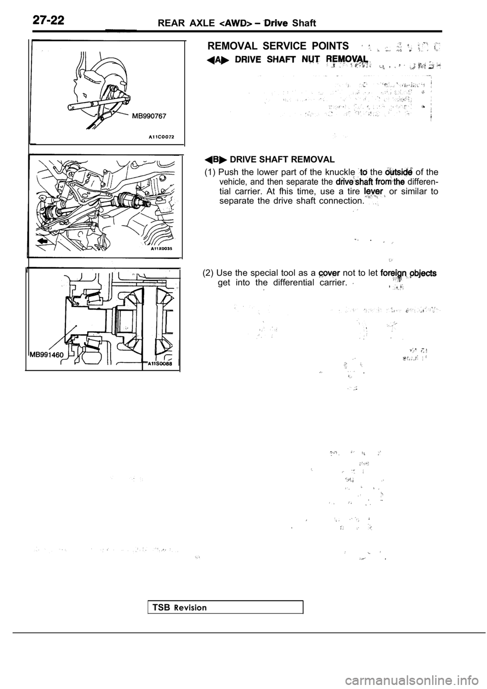
REMOVAL SERVICE POINTS
,
DRIVE SHAFT REMOVAL
(1) Push the lower part of the knuckle
the of the
vehicle, and then separate the differen-
tial carrier. At fhis time, use a tire or similar to
separate the drive shaft connection.
.
(2) Use the special tool as a not to let
get into the differential carrier. ,
,
TSB Revision
Page 1557 of 2103
REAR AXLE Shaft
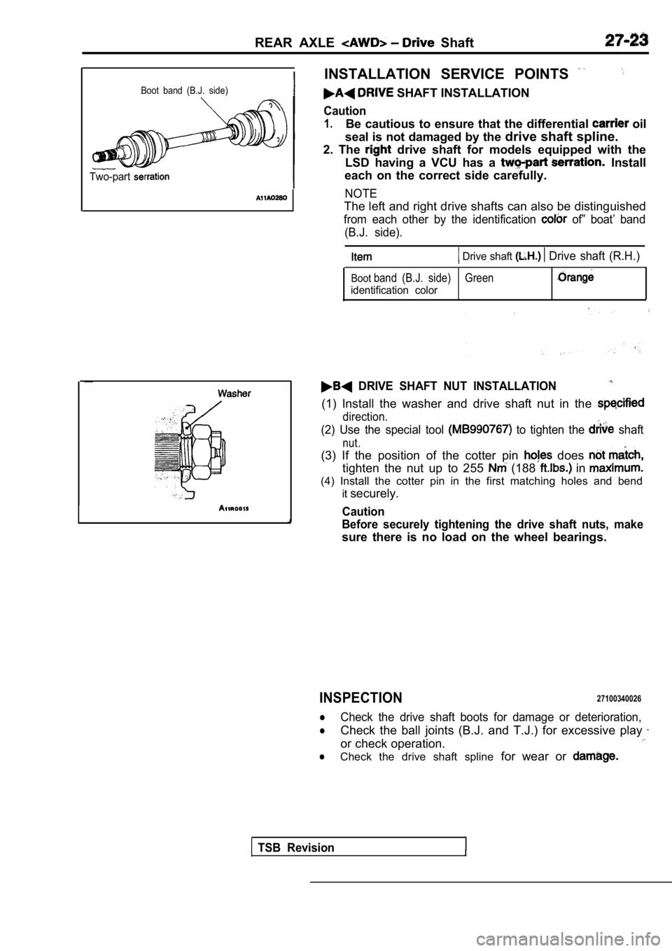
Boot band (B.J. side)
Two-part
INSTALLATION SERVICE POINTS
SHAFT INSTALLATION
Caution
1.Be cautious to ensure that the differential oil
seal is not damaged by the drive shaft spline.
2. The
drive shaft for models equipped with the
LSD having a VCU has a
Install
each on the correct side carefully.
NOTE
The left and right drive shafts can also be disting uished
from each other by the identification of” boat’ band
(B.J. side).
Drive shaft Drive shaft (R.H.)
Bootband (B.J. side) Green
identification color
DRIVE SHAFT NUT INSTALLATION
(1) Install the washer and drive shaft nut in the
direction.
(2) Use the special tool to tighten the shaft
nut.
(3) If the position of the cotter pin does
tighten the nut up to 255 (188 in
(4) Install the cotter pin in the first matching ho les and bend
it securely.
Caution
Before securely tightening the drive shaft nuts, ma ke
sure there is no load on the wheel bearings.
INSPECTION27100340026
lCheck the drive shaft boots for damage or deterioration,
lCheck the ball joints (B.J. and T.J.) for excessive play
or check operation.
lCheck the drive shaft spline for wear or
TSB Revision
Page 1558 of 2103
REAR AXLE Shaft
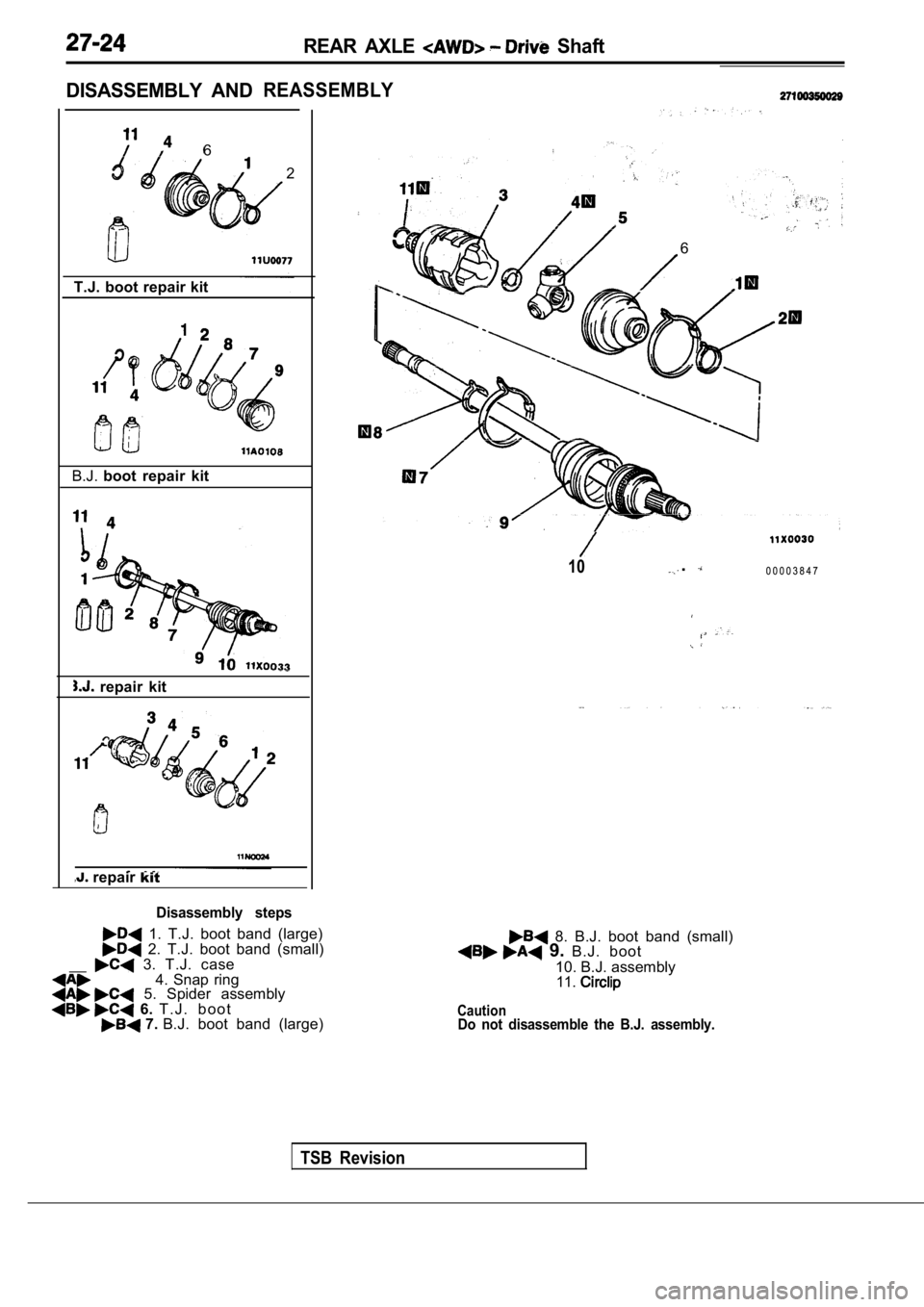
DISASSEMBLY AND
REASSEMBLY
6 2
T.J. boot repair kit
B.J. boot repair kit
repair kit
repair kit
Disassembly steps
1. T.J. boot band (large) 2. T.J. boot band (small)
__ 3. T.J. case4. Snap ring 5. Spider assembly 6. T . J . b o o t 7. B.J. boot band (large)Do not disassemble the B.J. assembly.
6
TSB Revision
10.0 0 0 0 3 8 4 7
8. B.J. boot band (small) 9. B.J. boot
10. B.J. assembly
11.
Caution
Page 1559 of 2103
REAR AXLE Drive Shaft
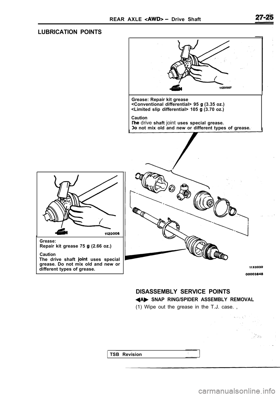
LUBRICATION POINTS
Grease:
Repair kit grease 75 (2.66 oz.)
Caution
The drive shaft uses special
grease. Do not mix old and new or
different types of grease. Grease: Repair kit grease
(3.35 oz.)
(3.70 oz.)
Caution
drive shaftjointuses special grease.
not mix old and new or different types of grease.
DISASSEMBLY SERVICE POINTS
SNAP RING/SPIDER ASSEMBLY REMOVAL
(1) Wipe out the grease in the T.J. case. ,
TSB Revision
Page 1560 of 2103
R E A R A X L E
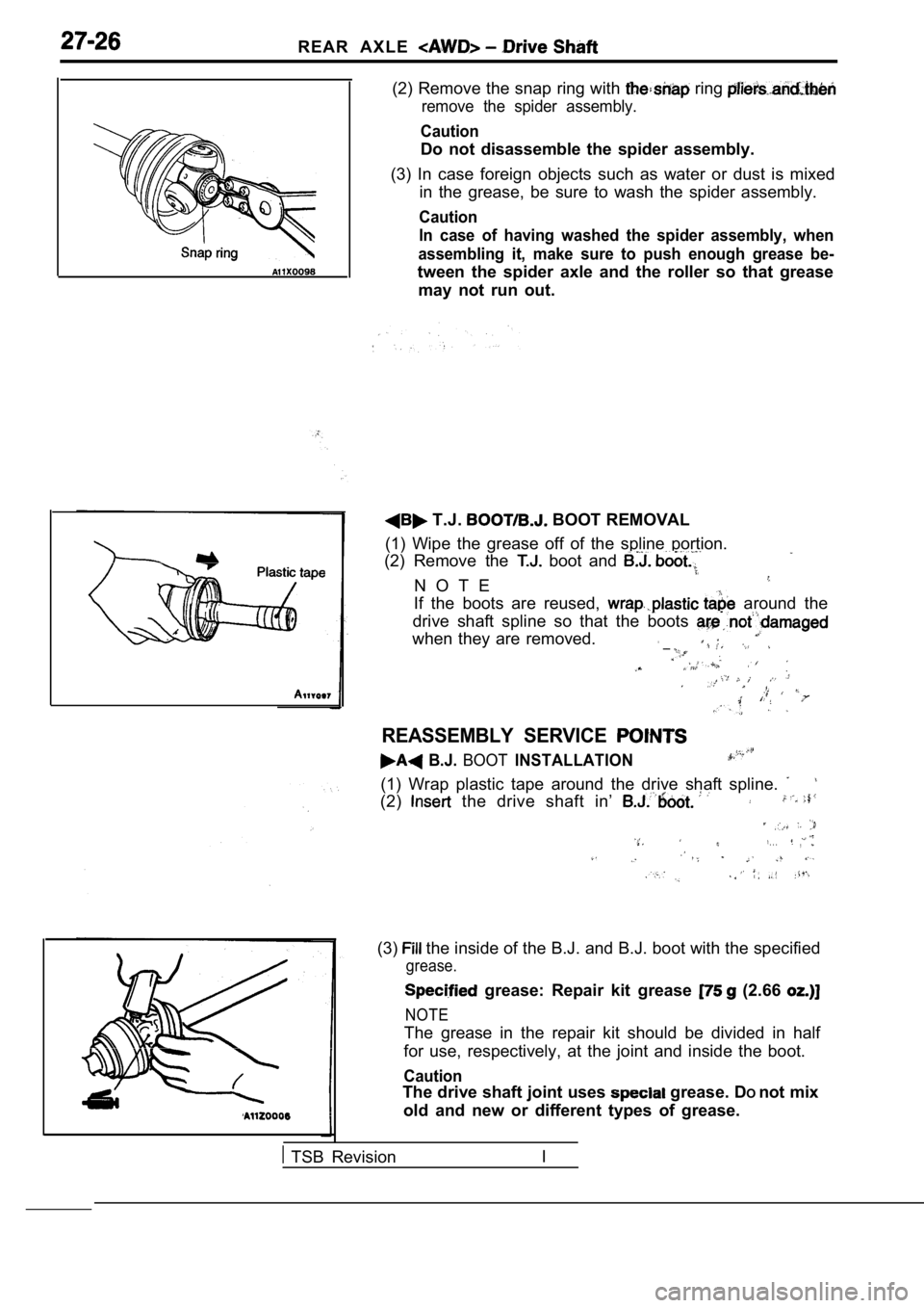
(2) Remove the snap ring with ring
remove the spider assembly.
Caution
Do not disassemble the spider assembly.
(3) In case foreign objects such as water or dust i s mixed
in the grease, be sure to wash the spider assembly.
Caution
In case of having washed the spider assembly, when
assembling it, make sure to push enough grease be-
tween the spider axle and the roller so that grease may not run out.
T.J. BOOT REMOVAL
(1) Wipe the grease off of the spline portion.
(2) Remove the
boot and
N O T E
If the boots are reused, around the
drive shaft spline so that the boots
when they are removed. __
REASSEMBLY SERVICE
B.J. BOOTINSTALLATION
(1) Wrap plastic tape around the drive shaft spline .
(2) the drive shaft in’
. . .,
(3) the inside of the B.J. and B.J. boot with the specified
grease.
grease: Repair kit grease (2.66
NOTE
The grease in the repair kit should be divided in h alf
for use, respectively, at the joint and inside the boot.
Caution
The drive shaft joint uses grease. DOnot mix
old and new or different types of grease.
TSB Revision I