MITSUBISHI SPYDER 1990 Service Repair Manual
SPYDER 1990
MITSUBISHI
MITSUBISHI
https://www.carmanualsonline.info/img/19/57345/w960_57345-0.png
MITSUBISHI SPYDER 1990 Service Repair Manual
Trending: oil pressure, wiring, suspension, wipers, air suspension, tire pressure reset, jacking
Page 671 of 2103
E N G I N E ( T U R B O )
AND ENGINE>
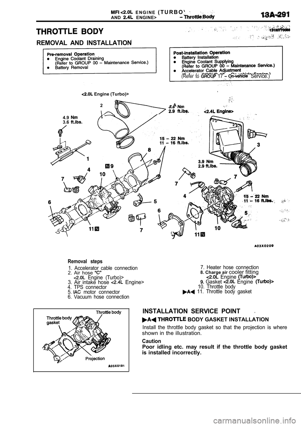
REMOVAL AND INSTALLATION
(Refer to 17 Service.)
Engine (Turbo)>
2 A . .
4.93.6
Removal steps
1. Accelerator cable connection2. Air hose Engine (Turbo)>3. Air intake hose Engine>4. TPS connector
5. motor connector
6. Vacuum hose connection 7. Heater hose connection
8. Charge air
cooler fitting Engine Gasket Engine10. Throttle body 11. Throttle body gasket
INSTALLATION SERVICE POINT.
BODY GASKET INSTALLATION
Install the throttle body gasket so that the projec tion is where
shown in the illustration.
Caution
Poor idling etc. may result if the throttle body ga sket
is installed incorrectly.
Page 672 of 2103
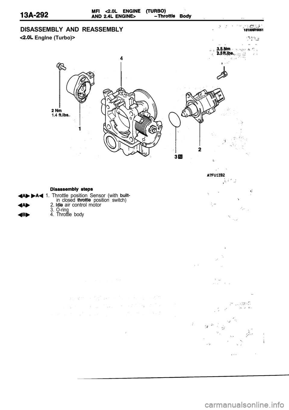
DISASSEMBLY AND REASSEMBLY
Englne (Turbo)>
4
1.4
,
I
1. Throttle position Sensor (with in closed position switch)2. air control motor
3. O-ring4. Throttle body
,
Page 673 of 2103
1.4
steps
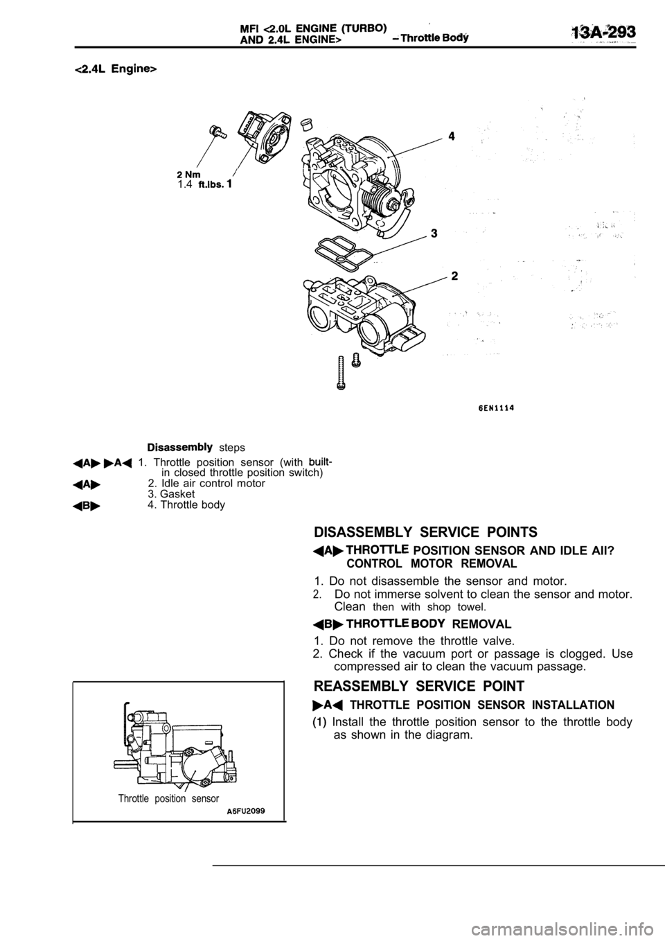
1. Throttle position sensor (with in closed throttle position switch)2. Idle air control motor
3. Gasket
4. Throttle body
DISASSEMBLY SERVICE POINTS
POSITION SENSOR AND IDLE All?
CONTROL MOTOR REMOVAL
1. Do not disassemble the sensor and motor.
2.Do not immerse solvent to clean the sensor and moto r.
Clean then with shop towel.
REMOVAL
1. Do not remove the throttle valve.
2. Check if the vacuum port or passage is clogged. Use
compressed air to clean the vacuum passage.
REASSEMBLY SERVICE POINT
THROTTLE POSITION SENSOR INSTALLATION
Install the throttle position sensor to the thrott le body
as shown in the diagram.
Throttle position sensor
Page 674 of 2103
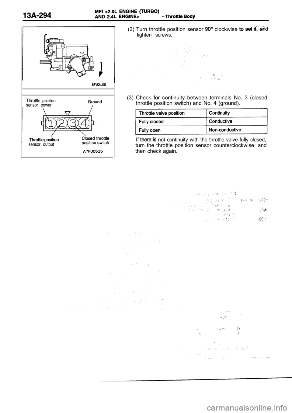
Throttlesensor powersensor output
(2) Turn throttle position sensor clockwise
tighten screws.
(3) Check for continuity between terminals No. 3 (c losed
throttle position switch) and No. 4 (ground).
If not continuity with the throttle valve fully close d,
turn the throttle position sensor counterclockwise, and
then check again.
Page 675 of 2103
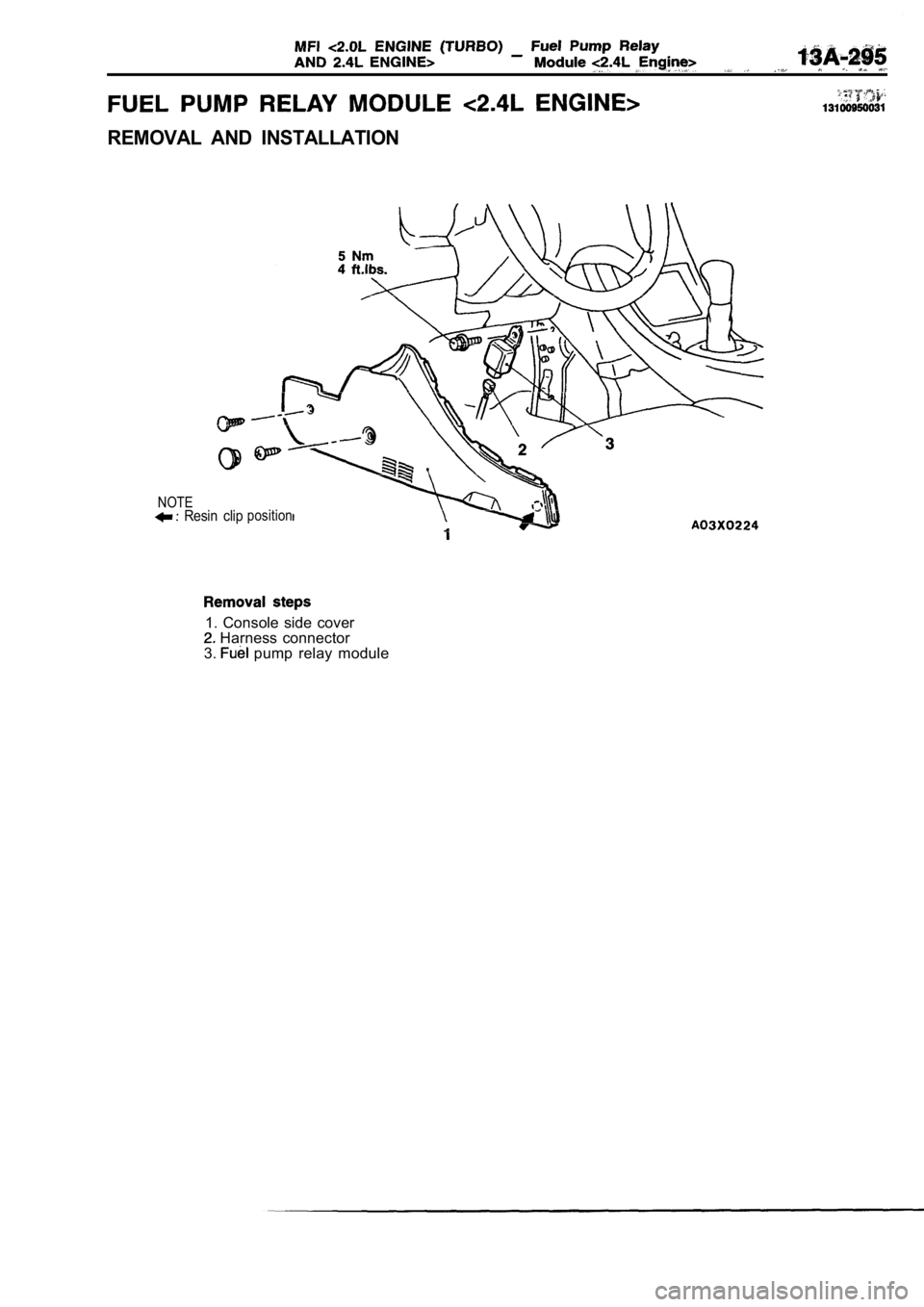
REMOVAL AND INSTALLATION
NOTE Resin clipposition
1. Console side cover Harness connector
3. pump relay module
Page 676 of 2103
Page 677 of 2103
, ,
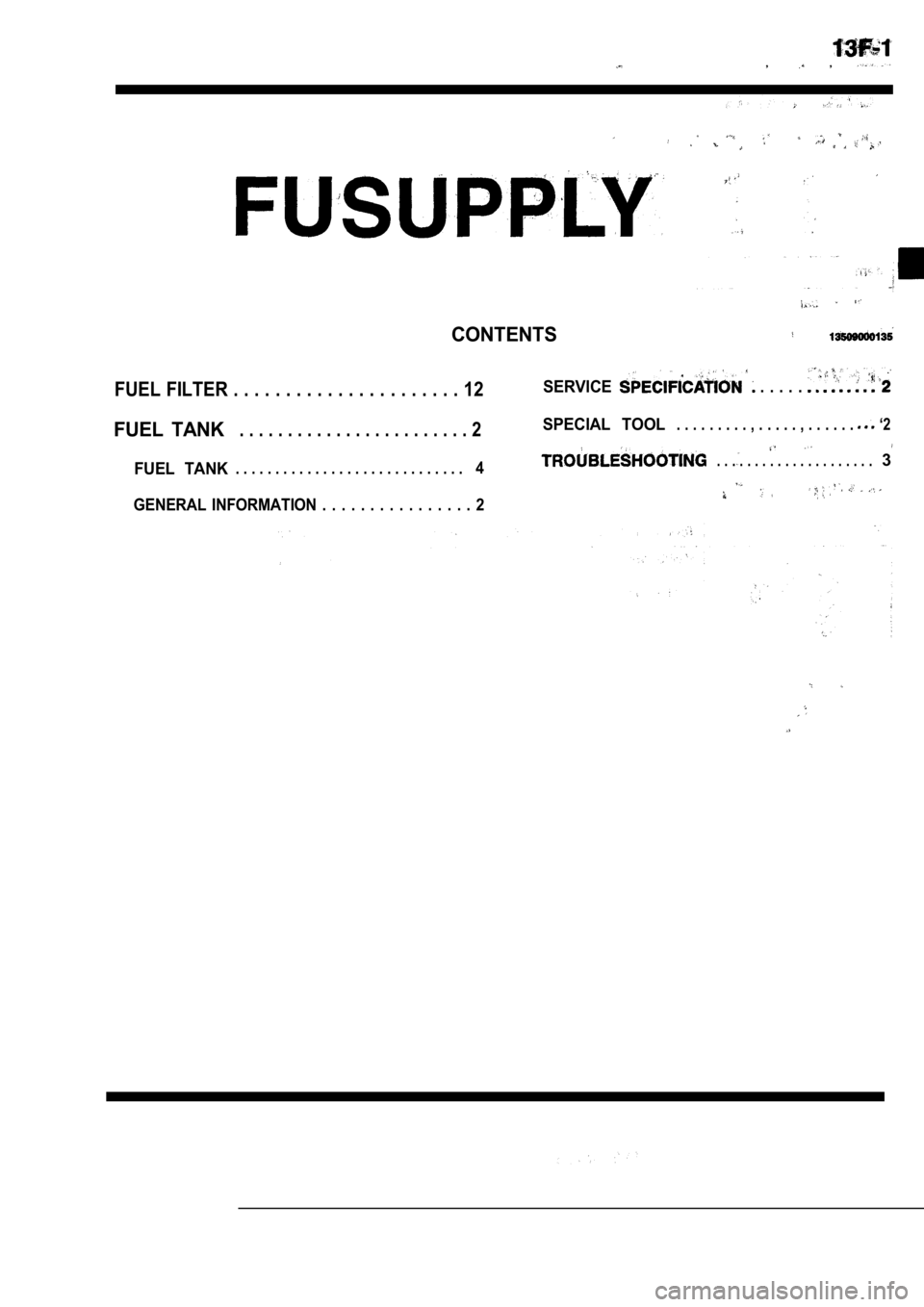
CONTENTS
FUEL FILTER . . . . . . . . . . . . . . . . . . . . . . 12SERVICE . . . . .
FUEL TANK. . . . . . . . . . . . . . . . . . . . . . . . 2SPECIAL TOOL. . . . . . . . . , . . . . . , . . . . . . ‘2
FUEL TANK4. . . . . . . . . . . . . . . . . . . . .3. . . . . . . . . . . . . . . . . . . . . . . . . . . . .
GENERAL INFORMATION . . . . . . . . . . . . . . . . 2
Page 678 of 2103
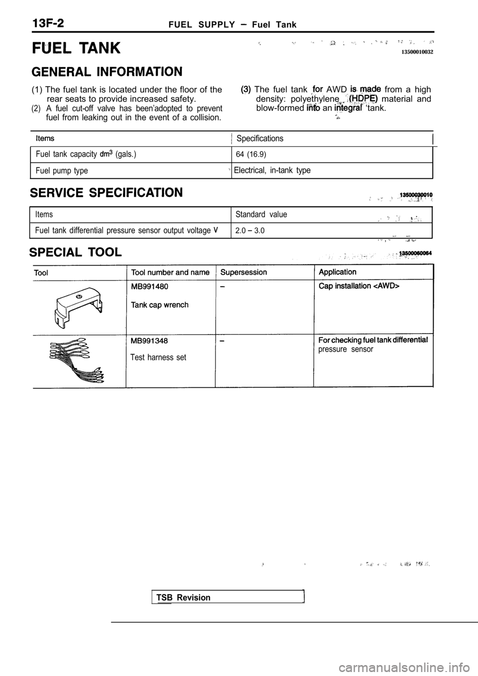
FUEL SUPPLY Fuel Tank
13500010032
(1) The fuel tank is located under the floor of the The fuel tank AWD from a high
rear seats to provide increased safety. density: pol yethylene
material and
(2)A fuel cut-off valve has been’adopted to preventblow-formed an ‘tank.
fuel from leaking out in the event of a collision.
Specifications
Fuel tank capacity (gals.)
Fuel pump type64 (16.9)
Electrical, in-tank type
ItemsStandard value.
Fuel tank differential pressure sensor output volta ge 2.0 3.0 ,
Test harness set pressure sensor
TSB Revision
Page 679 of 2103
FUEL SUPPLY -‘Fuel Tank
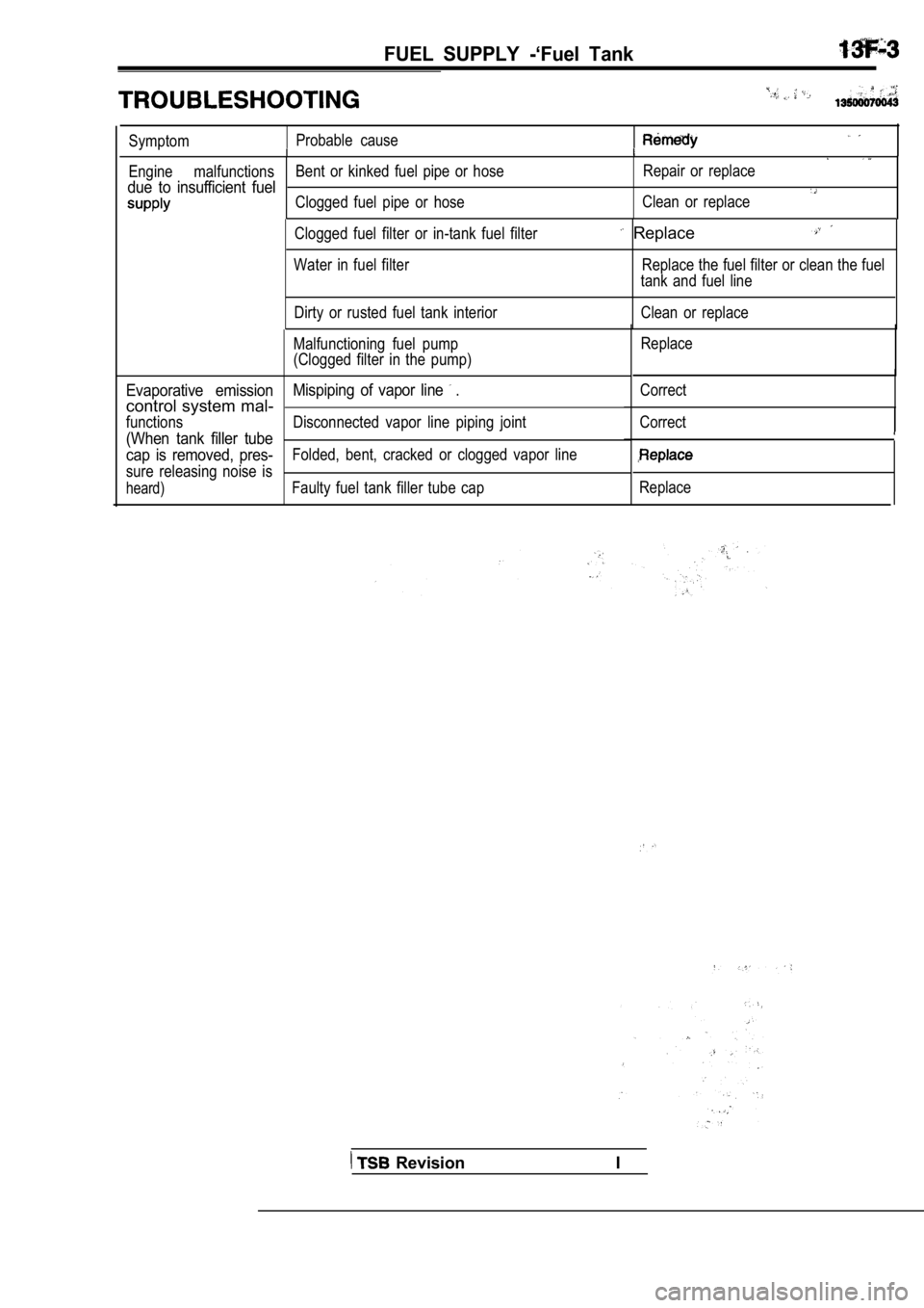
SymptomProbable cause
Engine malfunctions
Bent or kinked fuel pipe or hose Repair or replace
due to insufficient fuelClogged fuel pipe or hoseClean or replace
Clogged fuel filter or in-tank fuel filter
Water in fuel filter
Dirty or rusted fuel tank interior
Replace. .
Replace the fuel filter or clean the fuel
tank and fuel line
Clean or replace
Malfunctioning fuel pump
(Clogged filter in the pump)
Evaporative emission Mispiping of vapor line .
control system mal-
functions Disconnected vapor line piping joint
(When tank filler tube
cap is removed, pres-
Folded, bent, cracked or clogged vapor line
sure releasing noise is
heard)Faulty fuel tank filler tube cap Replace
Correct
CorrectReplace
Revision I
Page 680 of 2103
FUEL SUPPLY Tank
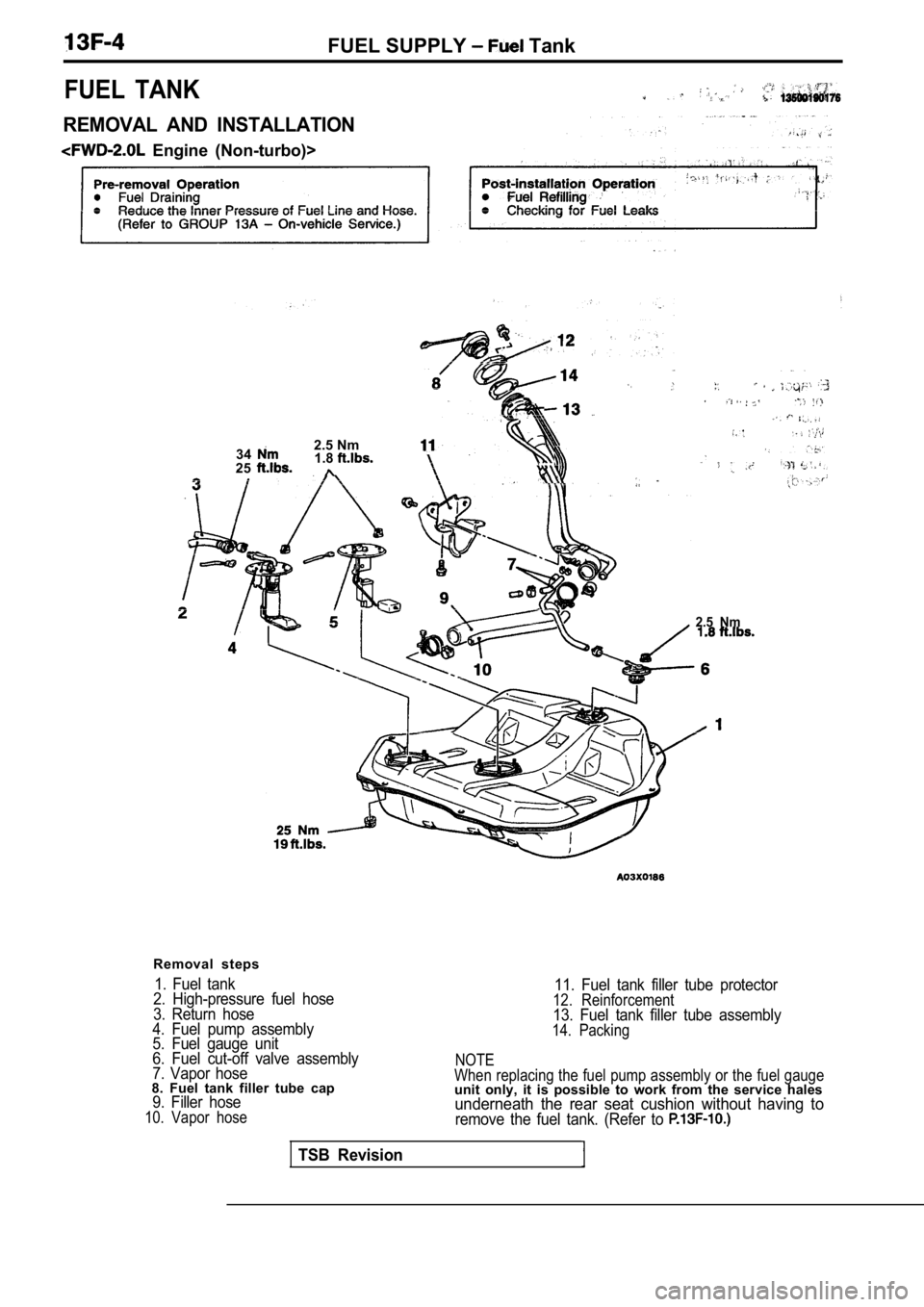
FUEL TANK
REMOVAL AND INSTALLATION
Engine (Non-turbo)>34
2.5 Nm
251.8
2.5 Nm
Removal steps
1. Fuel tank
2. High-pressure fuel hose
3. Return hose
4. Fuel pump assembly
5. Fuel gauge unit
6. Fuel cut-off valve assembly
7. Vapor hose
8. Fuel tank filler tube cap9. Filler hose10. Vapor hose
TSB Revision
11. Fuel tank filler tube protector12. Reinforcement13. Fuel tank filler tube assembly14. Packing
NOTE
When replacing the fuel pump assembly or the fuel g auge
unit only, it is possible to work from the service halesunderneath the rear seat cushion without having toremove the fuel tank. (Refer to
Trending: ad blue, child lock, belt, towing, key, seats, parking brake
