NISSAN ALMERA N15 1995 Service Manual
Manufacturer: NISSAN, Model Year: 1995, Model line: ALMERA N15, Model: NISSAN ALMERA N15 1995Pages: 1701, PDF Size: 82.27 MB
Page 1621 of 1701
RESTRAINTSYSTEM
SECTION
RS
CONTENTS
PRECAUTION 2
Supplemental RestraintSystem(SRS)"AIR
BAG" (DualAirBag System) 2
Supplemental RestraintSystem(SRS)"AIR
BAG" (Single AirBag System) 2
SEAT BELTS
3
Front SeatBelt 3
Rear SeatBel!. 5
SUPPLEMENTAL RESTRAINTSYSTEM(SRS) 8
Precautions forSRS "AirBag" and"Seat Belt
Pre-tensioner" Service 8
Special Service Tools 8
Description 9
SRS Component PartsLocation 10
Maintenance Items 11
Removal andInstallation -Diagnosis Sensor
Unit. 12
Removal andInstallation -Seat BeltPre-
tensioner (Mechanical Type) 13
Removal andInstallation -Air Bag Module
and Spiral Cable(DualAirBag System) 14
Removal andInstallation -Air Bag Module
and Spiral Cable(Single AirBag System) 14
Removal -Air Bag Module andSpiral Cable 15
Removal -Front Passenger AirBag Module
(Dual AirBag System) 16Installation
-Air Bag Module andSpiral
Cable 17
Installation -Front Passenger AirBag
Module (DualAirBag System) 18
Disposal ofAir Bag Module andSeat Belt
Pre-tensioner 19
TROUBLE DIAGNOSES -Supplemental
Restraint System(SRS) 25
How toPerform TroubleDiagnoses forQuick
and Accurate Repair 25
TROUBLE DIAGNOSES -Supplemental
Restraint System(SRS)-Dual AirBag System 28
Schematic 28
Wiring Diagram -SRS - 29
Self-diagnosis 32
Trouble Diagnoses forAir Bag Warning Lamp38
COLLISION DIAGNOSIS -Dual AirBag System .40
TROUBLE DIAGNOSES -Supplemental
Restraint System(SRS)-Single AirBag •
System 41•
Schematic 41
Wiring Diagram -SRS - 42
Self-diagnosis 43
COLLISION DIAGNOSIS -Single AirBag
System .45
COLLISION DIAGNOSIS -Seat Belt
Pre-tensioner
.46
When youread wiring diagrams:
• Read GIsection, "HOWTOREAD WIRING DIAGRAMS" .
• See ELsection, "POWER SUPPLYROUTING" forpower distribution circuit.
When youperform troublediagnoses, readGIsection, "HOWTOFOLLOW FLOWCHART
IN TROUBLE DIAGNOSES" and"HOW TOPERFORM EFFICIENT DIAGNOSIS FORAN
ELECTRICAL INCIDENT".
Page 1622 of 1701
PRECAUTION
Supplemental RestraintSystem(SRS)"AIR
BAG" (DualAirBag System)
The Supplemental RestraintSystem"AirBag", usedalong withaseat belt, helps toreduce therisk or
severity ofinjury tothe driver andfront passenger inafrontal collision. TheSupplemental Restraint
System consists ofair bag modules (locatedinthe center ofthe steering wheelandonthe instrument
panel onthe passenger side),adiagnosis sensorunit,warning lamp,wiring harness andspiral cable.
WARNING:
• Toavoid rendering theSRS inoperative, whichcouldincrease therisk ofpersonal injuryordeath
in the event ofacollision whichwould resultinair bag inflation, allmaintenance mustbeperformed
by an authorized NISSANdealer.
• Improper maintenance, includingincorrectremovalandinstallation ofthe SRS, canlead topersonal
injury caused byunintentional activationofthe system.
• Donot use electrical testequipment onany circuit related tothe SRS unless instructed tointhis
Service Manual. SRSwiring harnesses arecovered withyellow insulation eitherjustbefore the
harness connectors orfor the complete harness,foreasy identification.
Supplemental RestraintSystem(SRS)"AIR
BAG" (Single AirBag System)
The Supplemental RestraintSystem"AirBag", usedalong withaseat belt, helps toreduce therisk or
severity ofinjury tothe driver inafrontal collision. TheSupplemental RestraintSystemconsists ofan
air bag module (located inthe center ofthe steering wheel),adiagnosis sensorunit,warning lamp,
wiring harness andspiral cable.
WARNING:
• Toavoid rendering theSRS inoperative, whichcouldincrease therisk ofpersonal injuryordeath
in the event ofacollision whichwould resultinair bag inflation, allmaintenance mustbeperformed
by an authorized NISSANdealer.
• Improper maintenance, includingincorrectremovalandinstallation ofthe SRS, canlead topersonal
injury caused byunintentional activationofthe system.
• Donot use electrical testequipment onany circuit related tothe SRS unless instructed tointhis
Service Manual.
RS-2
Page 1623 of 1701
SEATBELTS
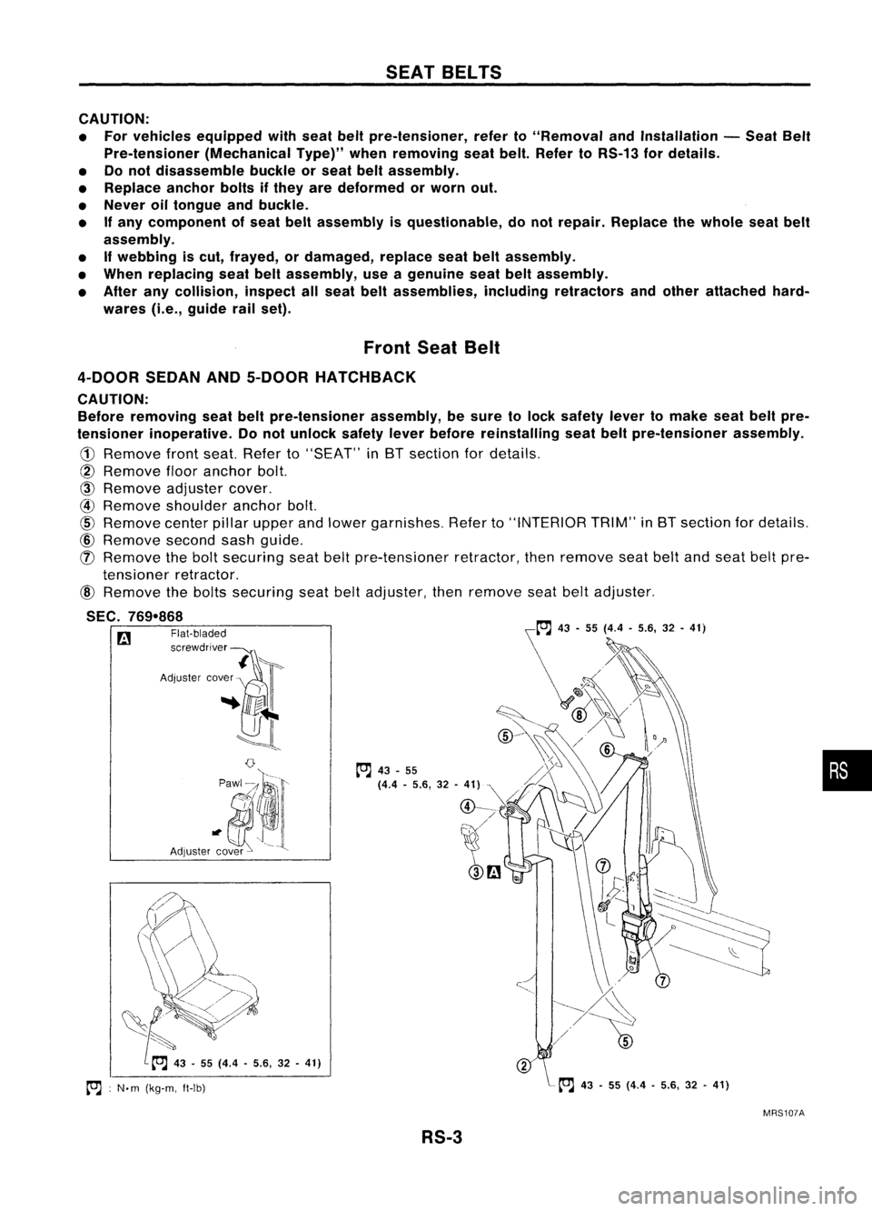
CAUTION:
• For vehicles equipped withseat beltpre-tensioner, referto"Removal andInstallation -Seat Belt
Pre-tensioner (MechanicalType)"whenremoving seatbelt. Refer toRS-13 fordetails.
• Donot disassemble buckleorseat beltassembly.
• Replace anchorboltsifthey aredeformed orworn out.
• Never oiltongue andbuckle.
• If
any component ofseat beltassembly isquestionable, donot repair. Replace thewhole seatbelt
assembly.
• Ifwebbing iscut, frayed, ordamaged, replaceseatbeltassembly.
• When replacing seatbeltassembly, useagenuine seatbeltassembly.
• After anycollision, inspectallseat beltassemblies, includingretractors andother attached hard-
wares (i.e.,guide railset).
•
toJ
43-55 (4.4 -5.6, 32-41)
A
~. t;//
~>-..,\
~t ..
~<:.~
~ 0
...
~
~ 43-55 (4.4 -5.6, 32-41)
toJ :
N.m (kg-m, ft-Ib)
Front
SeatBelt
4-DOOR SEDANAND5-DOOR HATCHBACK
CAUTION: Before removing seatbeltpre-tensioner assembly,besure tolock safety levertomake seatbeltpre-
tensioner inoperative. Donot unlock safetyleverbefore reinstalling seatbeltpre-tensioner assembly.
@ Remove flooranchor bolt.
@
Remove adjustercover.
@ Remove shoulder anchorbolt.
@
Remove centerpillarupper andlower garnishes. Referto"INTERIOR TRIM"inBT section fordetails.
@ Remove secondsashguide.
(J)
Remove thebolt securing seatbeltpre-tensioner retractor,thenremove seatbeltand seat beltpre-
tensioner retractor.
@
Remove thebolts securing seatbeltadjuster, thenremove seatbeltadjuster.
SEC. 769-868
rz1
MRS107A
RS-3
Page 1624 of 1701
SEATBELTS
Front SeatBelt(Cont'd)
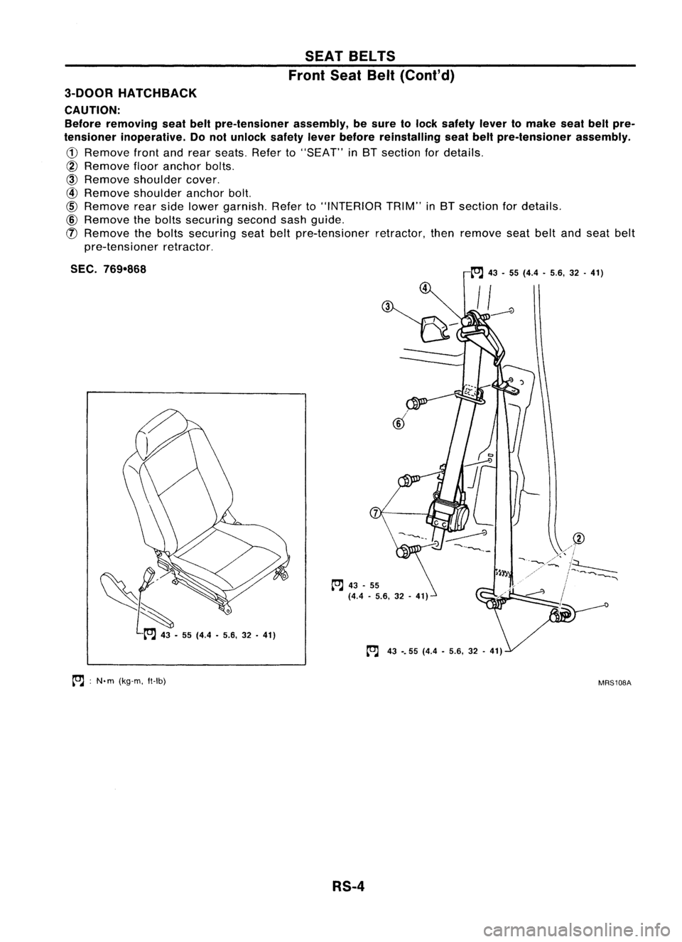
3-DOOR HATCHBACK
CAUTION: Before removing seatbeltpre-tensioner assembly,besure tolock safety levertomake seatbeltpre-
tensioner inoperative. Donot unlock safetyleverbefore reinstalling seatbeltpre-tensioner assembly.
CD
Remove frontandrear seats. Referto"SEAT" in8T section fordetails.
@
Remove flooranchor bolts.
@
Remove shoulder cover.
@
Remove shoulder anchorbolt.
@
Remove rearside lower garnish. Referto"INTERIOR TRIM"in8T section fordetails.
@
Remove thebolts securing secondsashguide.
(!)
Remove thebolts securing seatbeltpre-tensioner retractor,thenremove seatbeltandseat belt
pre-tensioner retractor.
SEC. 769-868
[OJ
43•55 (4.4 •5.6, 32.41)
tOJ
43-.55 (4.4•5.6, 32.41)
~~.
55(44 •5~" 32•41) ,
4
to.J
43•55
(4.4 •5.6, 32.41)
@
>~",
~//~«;~
~J. / /--...""
to.J :
N'm (kg-m. ft-Ib)
MRS108A
RS-4
Page 1625 of 1701
SEATBELTS
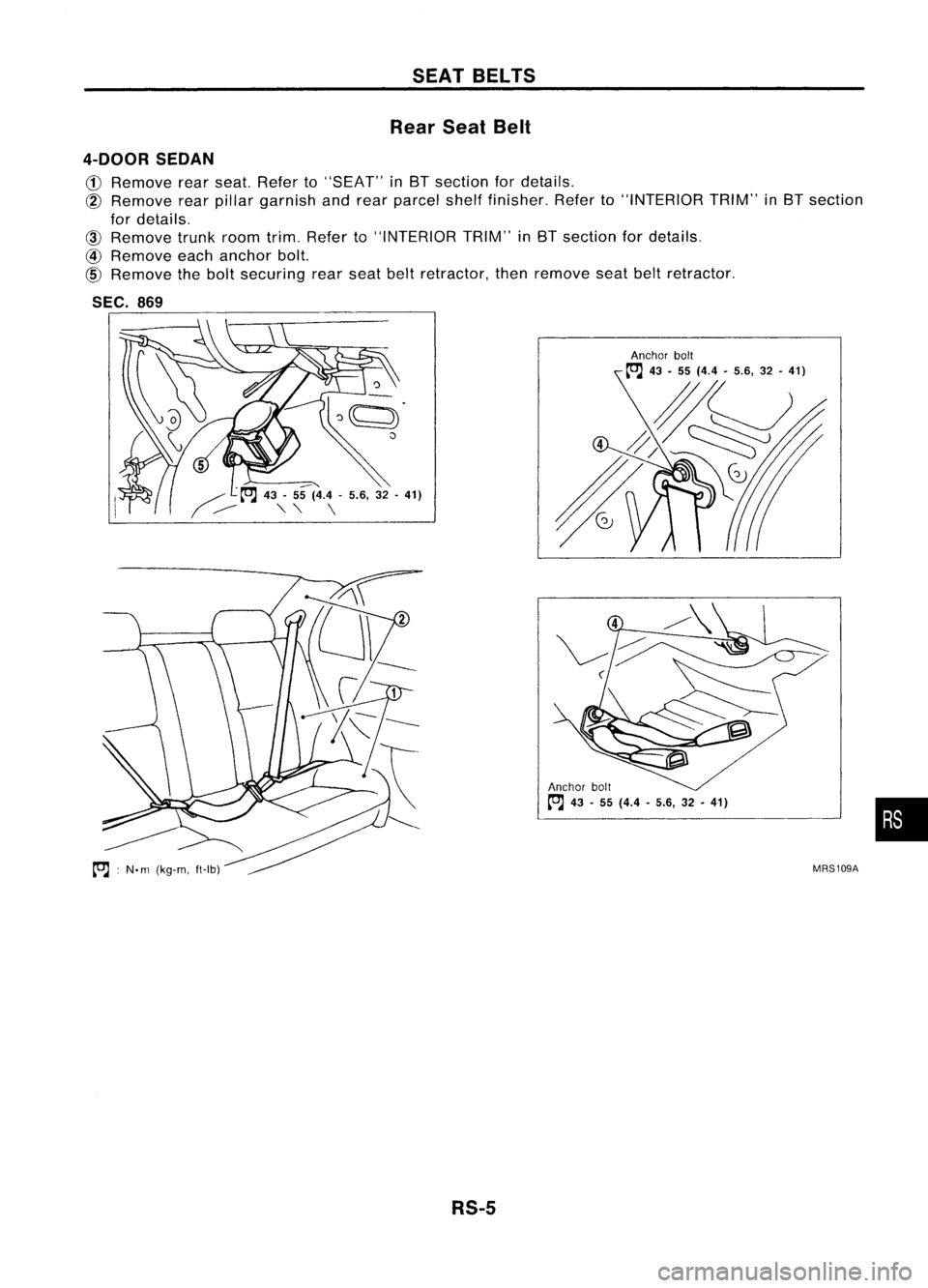
Rear SeatBelt
4-DOOR SEDAN
CD
Remove rearseat. Refer to"SEAT" inBT section fordetails,
@
Remove rearpillar garnish andrear parcel shelffinisher. Referto"INTERIOR TRIM"inBT section
for details.
@)
Remove trunkroomtrim.Refer to"INTERIOR TRIM"inBT section fordetails.
@
Remove eachanchor bolt.
@
Remove thebolt securing rearseat beltretractor, thenremove seatbeltretractor.
SEC. 869
~q.
5 '","" ~ ~
/" ~-A
43-55 (4.4 -5.6, 32-41)
/
----
""
\
•
MRS109A
Anchor
bolt
~ 43-55 (4.4 -5.6, 32•41)
~ :N.
m
(kg-m, ft-Ib)
RS-5
Page 1626 of 1701
SEATBELTS
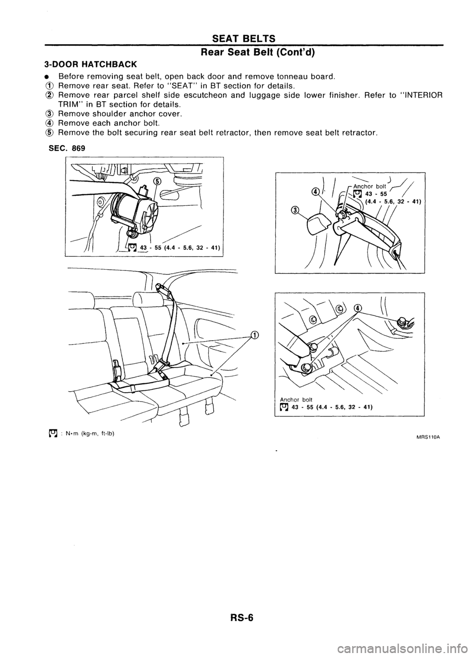
Rear SeatBelt(Cont'd)
3-DOOR HATCHBACK
• Before removing seatbelt,open backdoorandremove tonneau board.
CD
Remove rearseat. Refer to"SEAT" inBT section fordetails.
@
Remove rearparcel shelfsideescutcheon andluggage sidelower finisher. Referto"INTERIOR
TRIM" inBT section fordetails.
@)
Remove shoulder anchorcover.
@
Remove eachanchor bolt.
CID
Remove thebolt securing rearseat beltretractor, thenremove seatbeltretractor.
SEC. 869
to;J :
N'm (kg-m. ft-Ib)
RS-6
---------
)
/
Anchor bolt
I'll
..... [OJ
43•55
~ (4.4•5.6, 32-41)
Anchor bolt
to;J
43-55 (4.4 •5.6, 32-41)
MRS110A
Page 1627 of 1701
SEATBELTS
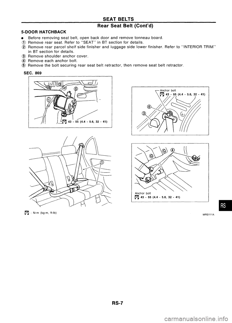
Rear SeatBelt(Cont'd)
5-DOOR HATCHBACK
• Before removing seatbelt,open backdoor andremove tonneau board.
CD
Remove rearseat. Refer to"SEAT" inBT section fordetails.
@
Remove rearparcel shelfsidefinisher andluggage sidelower finisher. Referto"INTERIOR TRIM"
in BT section fordetails.
@)
Remove shoulder anchorcover.
@
Remove eachanchor bolt.
@)
Remove thebolt securing rearseat beltretractor, thenremove seatbeltretractor.
SEC. 869
~ :N.m (kg-m, ft-Ib)
RS-7Anchor
bolt
~ 43-55 (4.4 -5.6, 32-41)
MRS111A
•
Page 1628 of 1701
SUPPLEMENTALRESTRAINTSYSTEM(SRS)
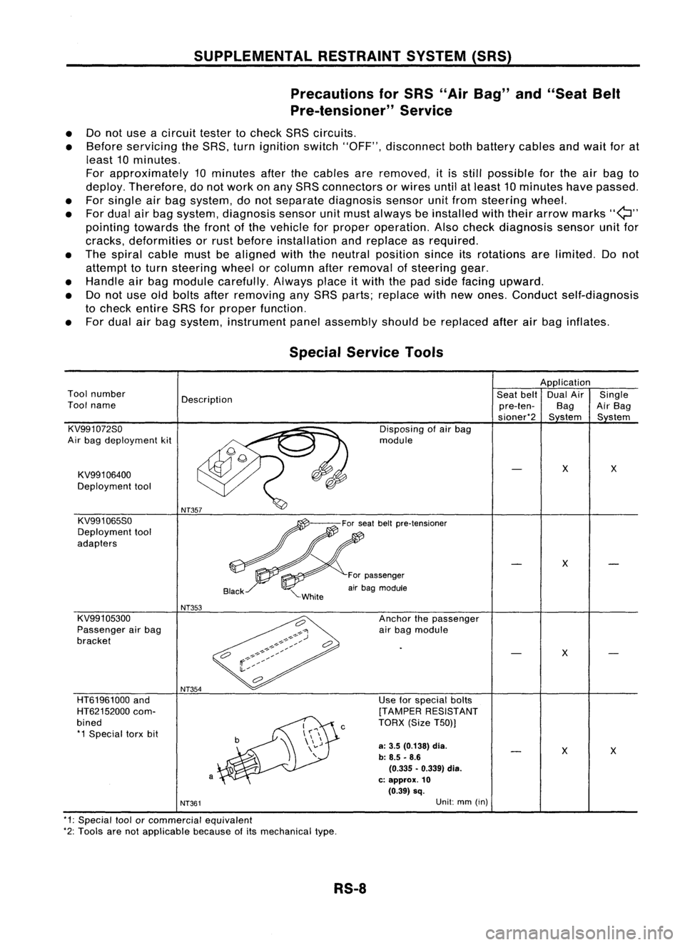
Precautions forSRS "AirBag" and"Seat Belt
Pre-tensioner" Service
• Donot use acircuit testertocheck SRScircuits.
• Before servicing theSRS. turnignition switch"OFF", disconnect bothbattery cablesandwait forat
least 10minutes.
For approximately 10minutes afterthecables areremoved, itis still possible forthe airbag to
deploy. Therefore, donot work onany SRS connectors orwires untilatleast 10minutes havepassed.
• For single airbag system, donot separate diagnosis sensorunitfrom steering wheel.
• For dual airbag system. diagnosis sensorunitmust always beinstalled withtheir arrow marks
"Q"
pointing towards thefront ofthe vehicle forproper operation. Alsocheck diagnosis sensorunitfor
cracks. deformities orrust before installation andreplace asrequired.
• The spiral cablemustbealigned withtheneutral position sinceitsrotations arelimited. Donot
attempt toturn steering wheelorcolumn afterremoval ofsteering gear.
• Handle airbag module carefully. Alwaysplaceitwith thepad side facing upward.
• Donot use oldbolts afterremoving anySRS parts; replace withnewones. Conduct self-diagnosis
to check entire SRSforproper function.
• For dual airbag system, instrument panelassembly shouldbereplaced afterairbag inflates.
X
X
Use
forspecial bolts
[TAMPER RESISTANT
TORX (SizeT50))
a:
3.5 (0.138)
dia.
b: 8.5 -8.6
(0.335 •0.339) dia.
c: approx.
10
(0.39) sq.
c
NT354
a
HT61961000
and
HT62152000 com-
bined *1 Special torxbit
Special
Service Tools
Application
Tool number
Description Seat
belt DualAir Single
Tool name
pre-ten-BagAirBag
sioner*2 Sstem Sstem
KV991072So Disposingofair bag
Air bag deployment kit module
KV991 06400
X
X
Deployment tool
KV991065So
Deployment tool
adapters
X
For passenger
air bag module
NT353
KV991 05300 Anchorthepassenger
Passenger airbag
airbag module
bracket
X
NT361
Unit:
mm(in)
*1: Special toolorcommercial equivalent
*2: Tools arenotapplicable becauseofits mechanical type.
RS-8
Page 1629 of 1701
SUPPLEMENTALRESTRAINTSYSTEM(SRS)
Description
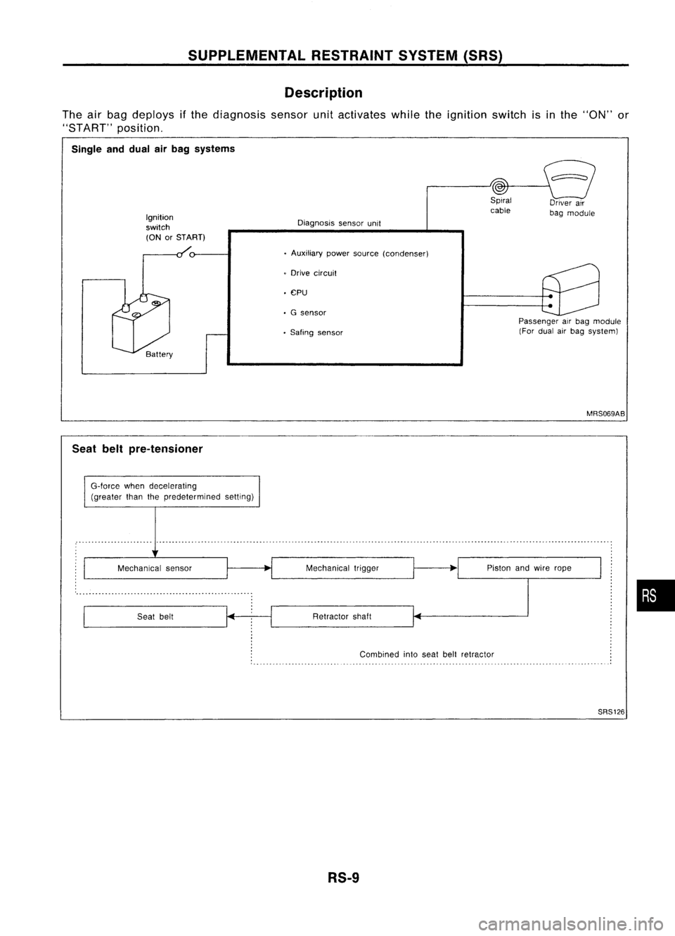
The airbag deploys ifthe diagnosis sensorunitactivates whiletheignition switchisinthe "ON" or
"START" position.
Single anddual airbag systems
Ignition
switch
(ON orSTART)
Driver
air
bag module
Diagnosis sensorunit
• Auxiliary powersource (condenser)
• CPU
Battery
Seat beltpre-tensioner
G-Iorce whendecelerating
(greater thanthepredetermined setting)
o
Drive circuit
• G sensor
• Saling sensor Passenger
airbag module
(For dual airbag system)
MRS069AB
Mechanical sensor
Seat belt Mechanical
trigger
Retractor shaft Piston
andwire rope
•
Combined intoseat beltretractor
SRS126
RS-9
Page 1630 of 1701
SUPPLEMENTALRESTRAINTSYSTEM(SRS)
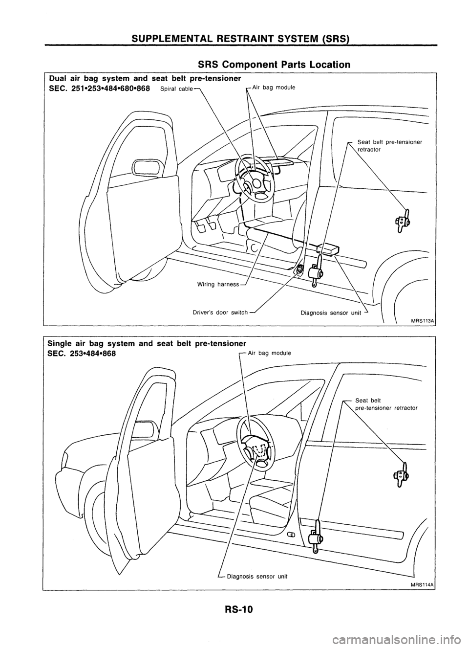
SRS Component PartsLocation
Dual airbag system andseat beltpre-tensioner
SEC. 251-253-484-680-868 Spiralcable Airbag module
Diagnosis sensorunit
Single airbag system andseat beltpre-tensioner
SEC. 253-484-868 Airbag module
Diagnosis sensorunit
RS-10 MRS114A