NISSAN ALMERA N16 2003 Electronic Repair Manual
ALMERA N16 2003
NISSAN
NISSAN
https://www.carmanualsonline.info/img/5/57350/w960_57350-0.png
NISSAN ALMERA N16 2003 Electronic Repair Manual
Trending: APP, junction box b4, Start, cooling fan wiring diagram, mil, sensor, Panel
Page 2381 of 3189
YEL810D
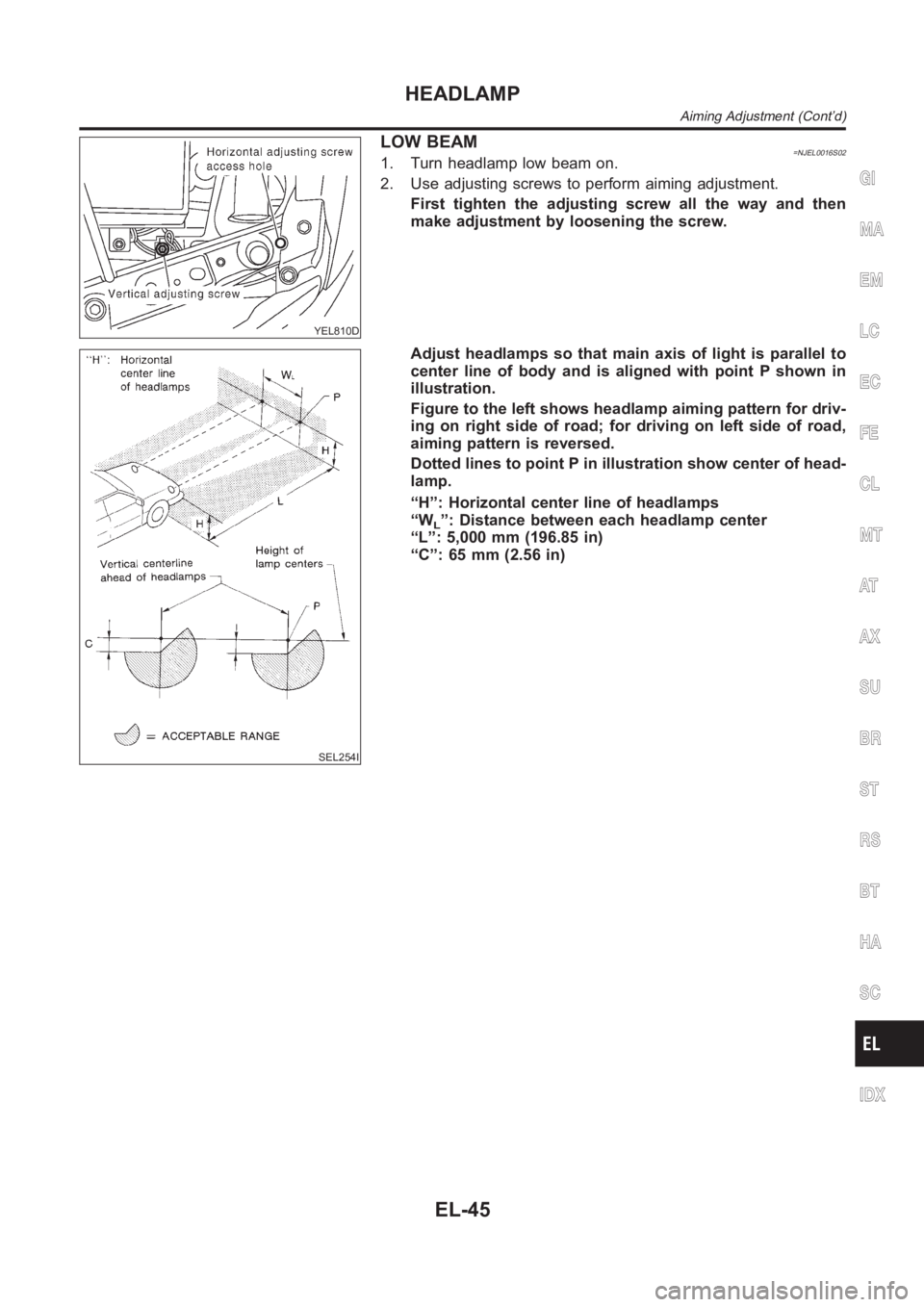
LOW BEAM=NJEL0016S021. Turn headlamp low beam on.
2. Use adjusting screws to perform aiming adjustment.
First tighten the adjusting screw all the way and then
make adjustment by loosening the screw.
SEL254I
Adjust headlamps so that main axis of light is parallel to
center line of body and is aligned with point P shown in
illustration.
Figure to the left shows headlamp aiming pattern for driv-
ing on right side of road; for driving on left side of road,
aiming pattern is reversed.
Dotted lines to point P in illustration show center of head-
lamp.
“H”: Horizontal center line of headlamps
“W
L”: Distance between each headlamp center
“L”: 5,000 mm (196.85 in)
“C”: 65 mm (2.56 in)
GI
MA
EM
LC
EC
FE
CL
MT
AT
AX
SU
BR
ST
RS
BT
HA
SC
IDX
HEADLAMP
Aiming Adjustment (Cont’d)
EL-45
Page 2382 of 3189
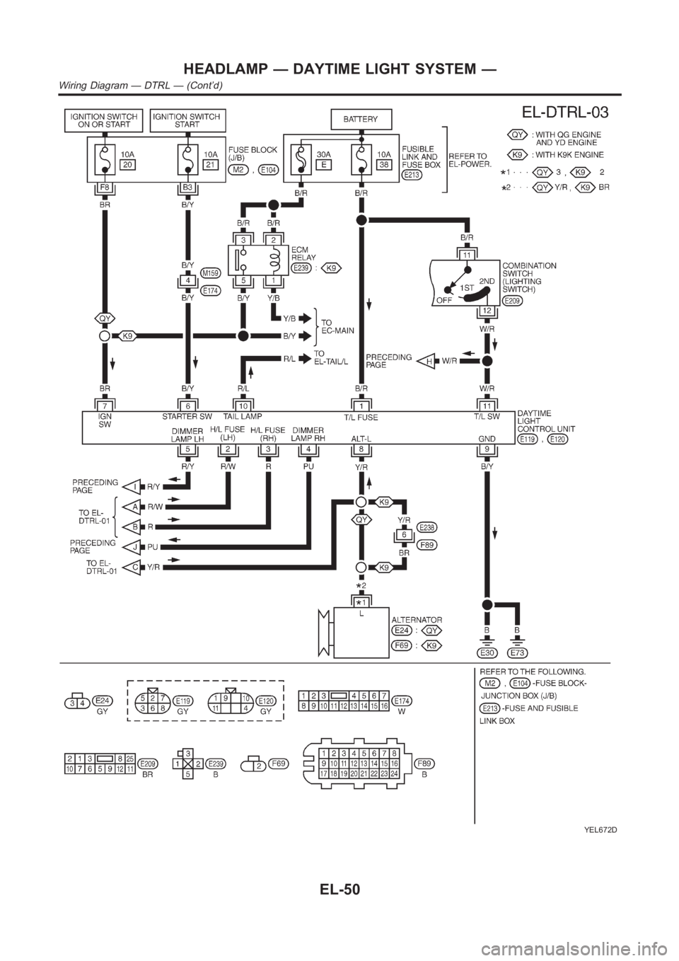
System DescriptionNJEL0351The headlamp system on vehicles for cold spec. option contains a daytime light unit. The unit activates the
following whenever the engine is running with the lighting switch in the OFF position:
Low beam headlamps
Parking, license, tail and illumination lamps
Power is supplied at all times
through 10A fuse (No. 38, located in the fusible link and fuse box)
to daytime light unit terminal 1 and
to lighting switch terminal 11.
Power is also supplied at all times
through 15A fuse (No. 36, located in the fusible link and fuse box)
to daytime light unit terminal 3 and
to lighting switch terminal 5.
Power is also supplied at all times
through 15A fuse (No. 35, located in the fusible link and fuse box)
to daytime light unit terminal 2 and
to lighting switch terminal 8.
With the ignition switch in the ON or START position, power is supplied
through 10A fuse [No. 20, located in the fuse block (J/B)]
to daytime light unit terminal 7.
With the ignition switch in the START position, power is supplied
through 10A fuse [No. 21, located in the fuse block (J/B)]
to daytime light unit terminal 6.
Ground is supplied to daytime light unit terminal 9 through body grounds E30 and E73.
HEADLAMP OPERATION (DAYTIME LIGHT CANCEL OPERATION)NJEL0351S01When the lighting switch is turned to the 1st or 2nd position, power is supplied
through lighting switch terminal 12,
to daytime light unit terminal 11.
Then daytime light will be canceled. And the lighting system operation will be the same as no daytime light
system.
DAYTIME LIGHT OPERATIONNJEL0351S02With the engine running and the lighting switch in the OFF position, power is supplied
from alternator terminal 3
to daytime light unit terminal 8,
through daytime light unit terminal 5
to terminal 4 of headlamp LH,
through daytime light unit terminal 4
to terminal 2 of headlamp RH and
through daytime light unit terminal 10
to tail lamp and illumination.
Ground is supplied to terminal 5 of headlamp LH and terminal 1 of headlamp RHthrough body grounds E30
and E73.
HEADLAMP — DAYTIME LIGHT SYSTEM —
System Description
EL-46
Page 2383 of 3189
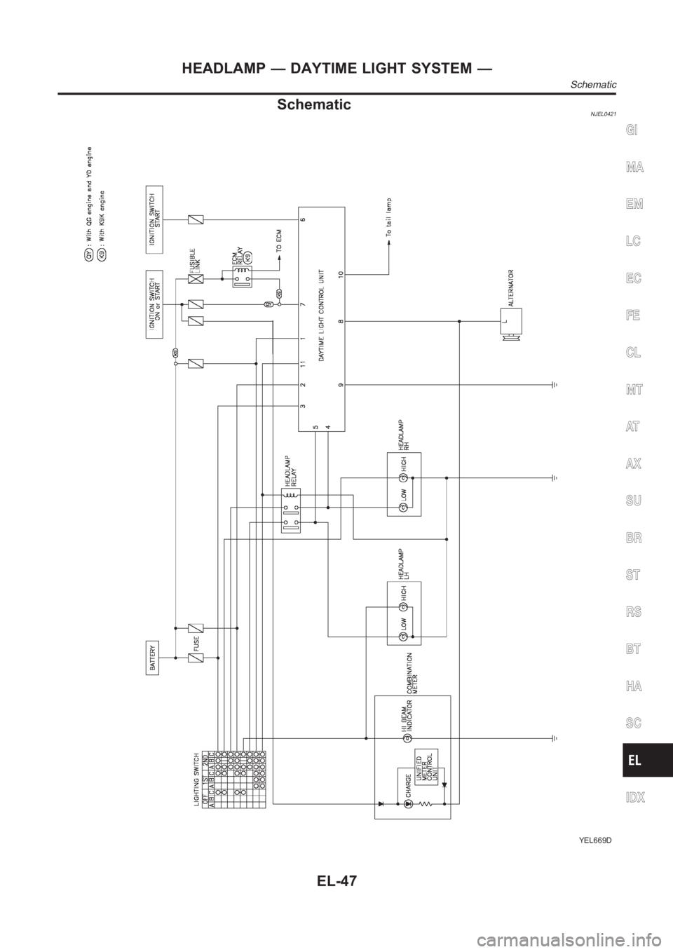
SchematicNJEL0421
YEL669D
GI
MA
EM
LC
EC
FE
CL
MT
AT
AX
SU
BR
ST
RS
BT
HA
SC
IDX
HEADLAMP — DAYTIME LIGHT SYSTEM —
Schematic
EL-47
Page 2384 of 3189
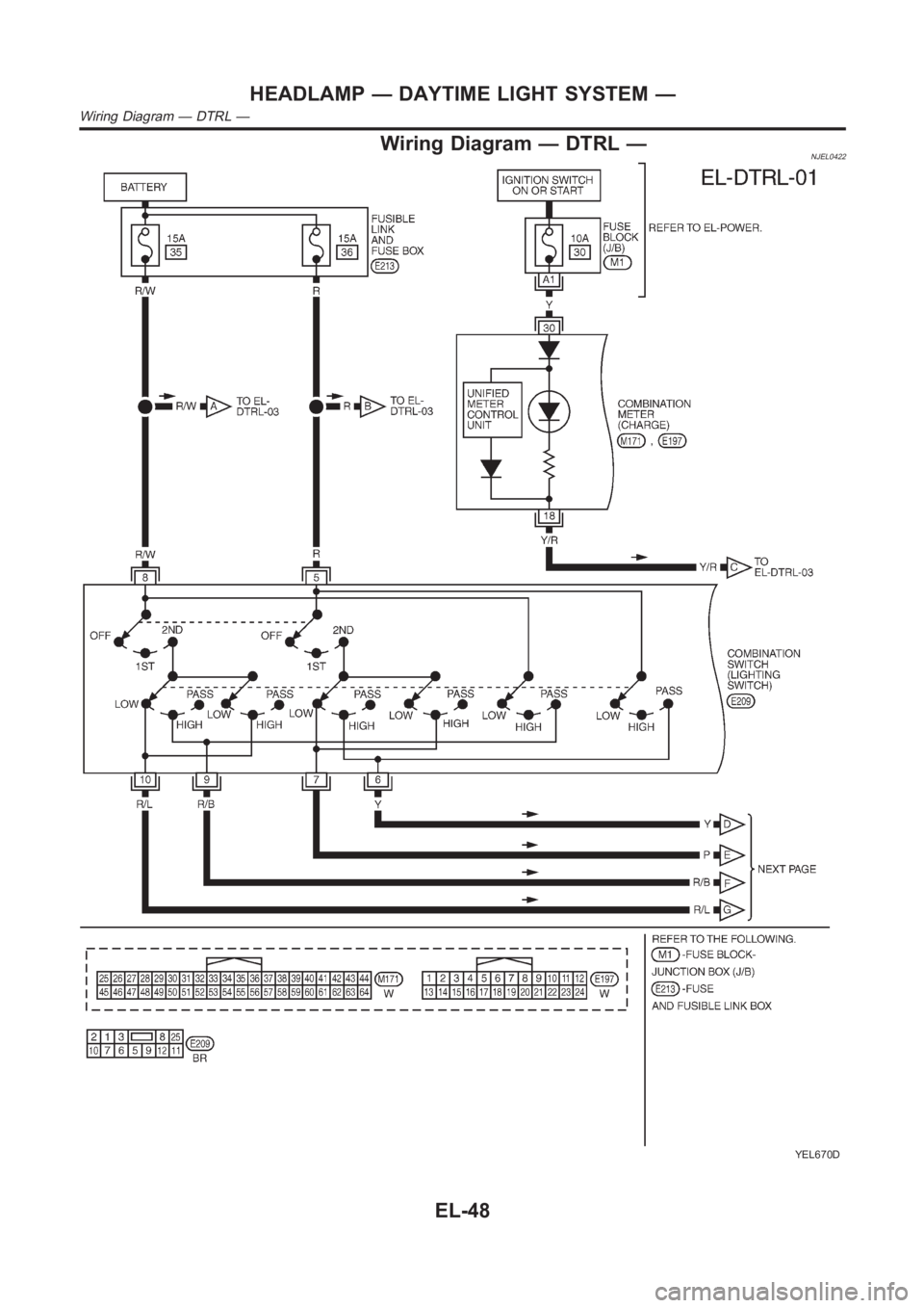
Wiring Diagram — DTRL —NJEL0422
YEL670D
HEADLAMP — DAYTIME LIGHT SYSTEM —
Wiring Diagram — DTRL —
EL-48
Page 2385 of 3189
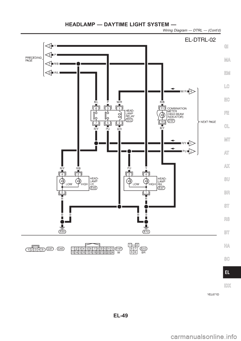
YEL671D
GI
MA
EM
LC
EC
FE
CL
MT
AT
AX
SU
BR
ST
RS
BT
HA
SC
IDX
HEADLAMP — DAYTIME LIGHT SYSTEM —
Wiring Diagram — DTRL — (Cont’d)
EL-49
Page 2386 of 3189
YEL672D
HEADLAMP — DAYTIME LIGHT SYSTEM —
Wiring Diagram — DTRL — (Cont’d)
EL-50
Page 2387 of 3189
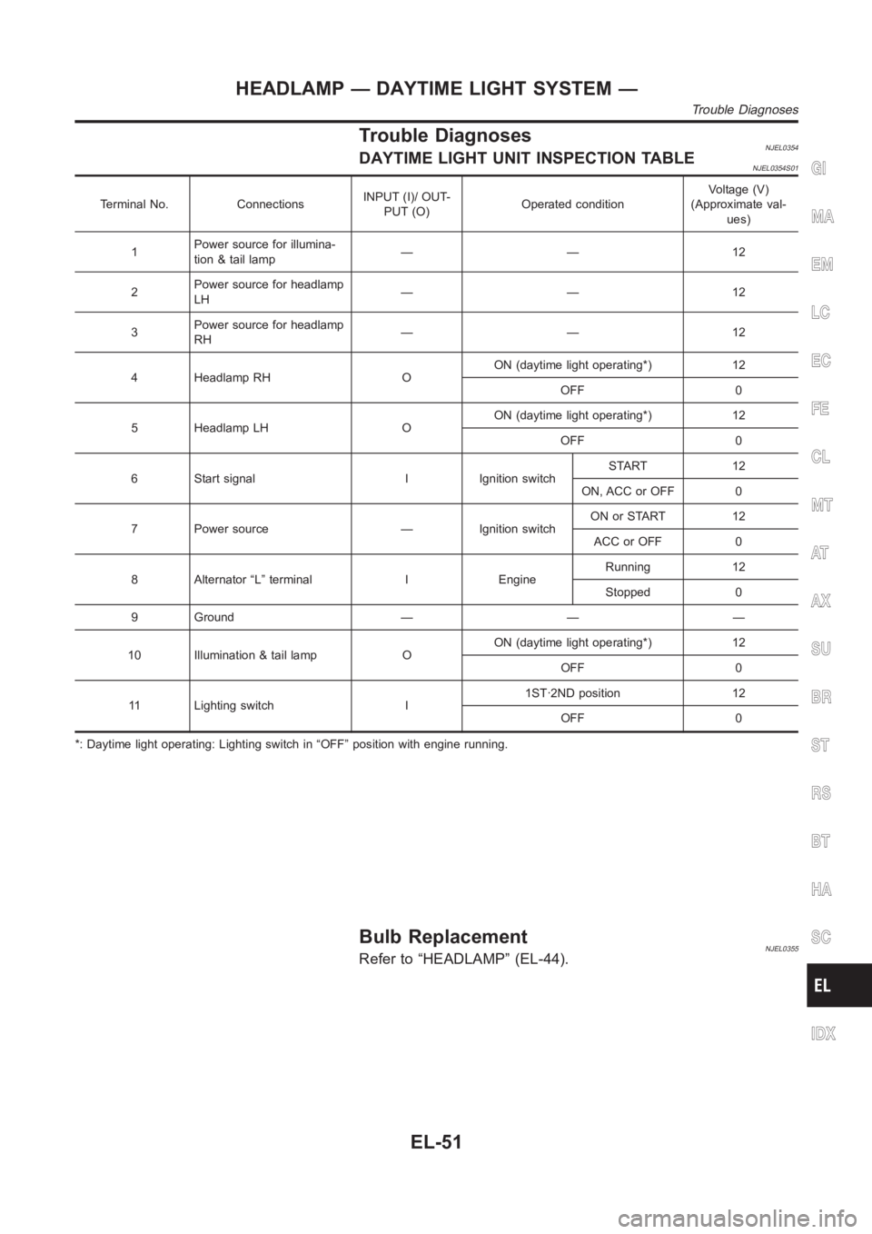
Trouble DiagnosesNJEL0354DAYTIME LIGHT UNIT INSPECTION TABLENJEL0354S01
Terminal No. ConnectionsINPUT (I)/ OUT-
PUT (O)Operated conditionVoltage (V)
(Approximate val-
ues)
1Power source for illumina-
tion & tail lamp——12
2Power source for headlamp
LH——12
3Power source for headlamp
RH——12
4 Headlamp RH OON (daytime light operating*) 12
OFF 0
5 Headlamp LH OON (daytime light operating*) 12
OFF 0
6 Start signal I Ignition switchSTART 12
ON, ACC or OFF 0
7 Power source — Ignition switchON or START 12
ACC or OFF 0
8 Alternator “L” terminal I EngineRunning 12
Stopped 0
9 Ground — — —
10 Illumination & tail lamp OON (daytime light operating*) 12
OFF 0
11 Lighting switch I1ST·2ND position 12
OFF 0
*: Daytime light operating: Lighting switch in “OFF” position with enginerunning.
Bulb ReplacementNJEL0355Refer to “HEADLAMP” (EL-44).
GI
MA
EM
LC
EC
FE
CL
MT
AT
AX
SU
BR
ST
RS
BT
HA
SC
IDX
HEADLAMP — DAYTIME LIGHT SYSTEM —
Trouble Diagnoses
EL-51
Page 2388 of 3189
Aiming AdjustmentNJEL0356Refer to “HEADLAMP” (EL-44).
HEADLAMP — DAYTIME LIGHT SYSTEM —
Aiming Adjustment
EL-52
Page 2389 of 3189
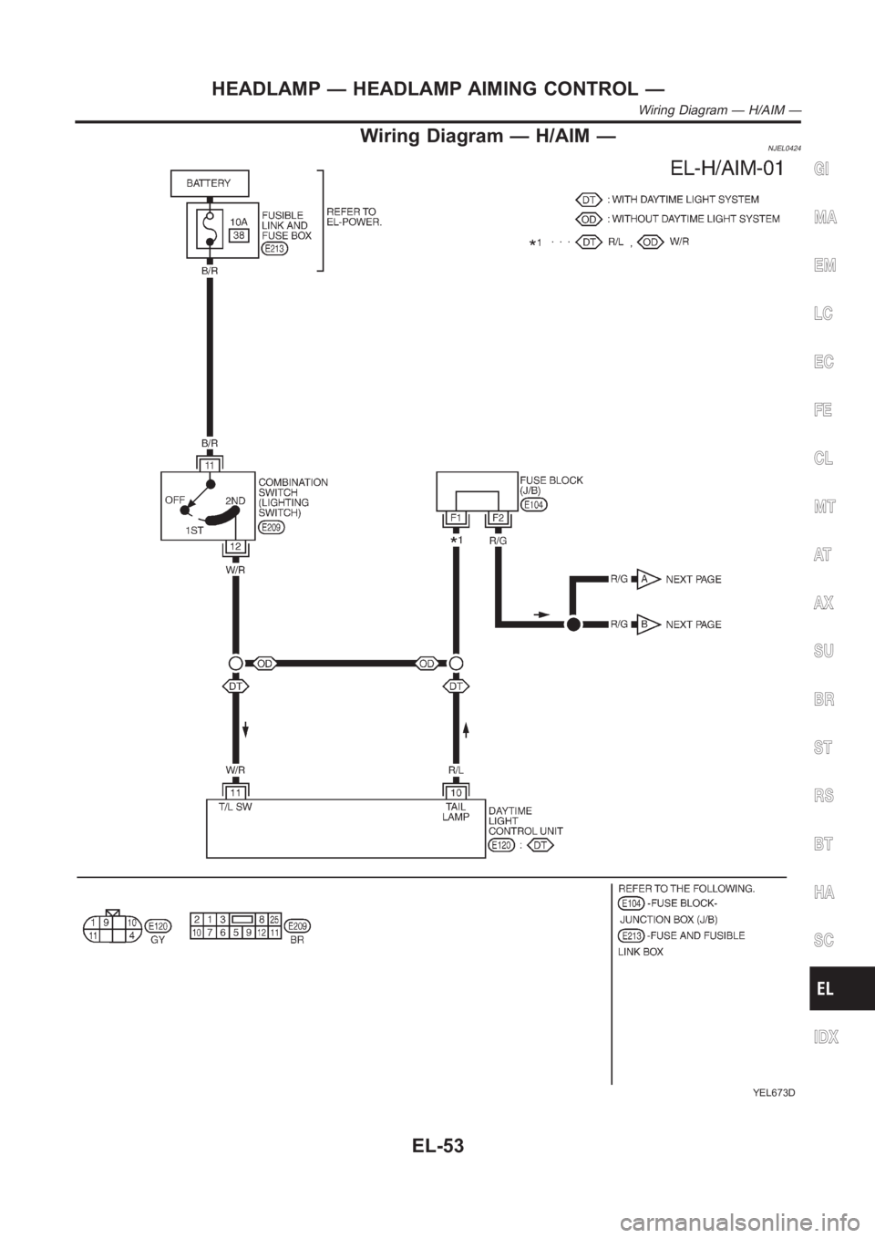
Wiring Diagram — H/AIM —NJEL0424
YEL673D
GI
MA
EM
LC
EC
FE
CL
MT
AT
AX
SU
BR
ST
RS
BT
HA
SC
IDX
HEADLAMP — HEADLAMP AIMING CONTROL —
Wiring Diagram — H/AIM —
EL-53
Page 2390 of 3189
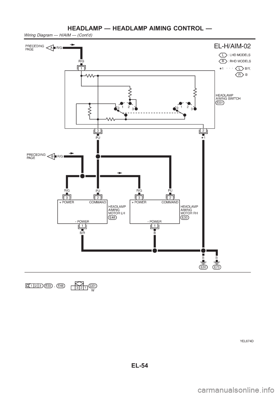
YEL674D
HEADLAMP — HEADLAMP AIMING CONTROL —
Wiring Diagram — H/AIM — (Cont’d)
EL-54
Trending: EL-, ecm, APP, ground, Ecu, gas type, odometer
