NISSAN ALMERA N16 2003 Electronic Repair Manual
Manufacturer: NISSAN, Model Year: 2003, Model line: ALMERA N16, Model: NISSAN ALMERA N16 2003Pages: 3189, PDF Size: 54.76 MB
Page 2401 of 3189
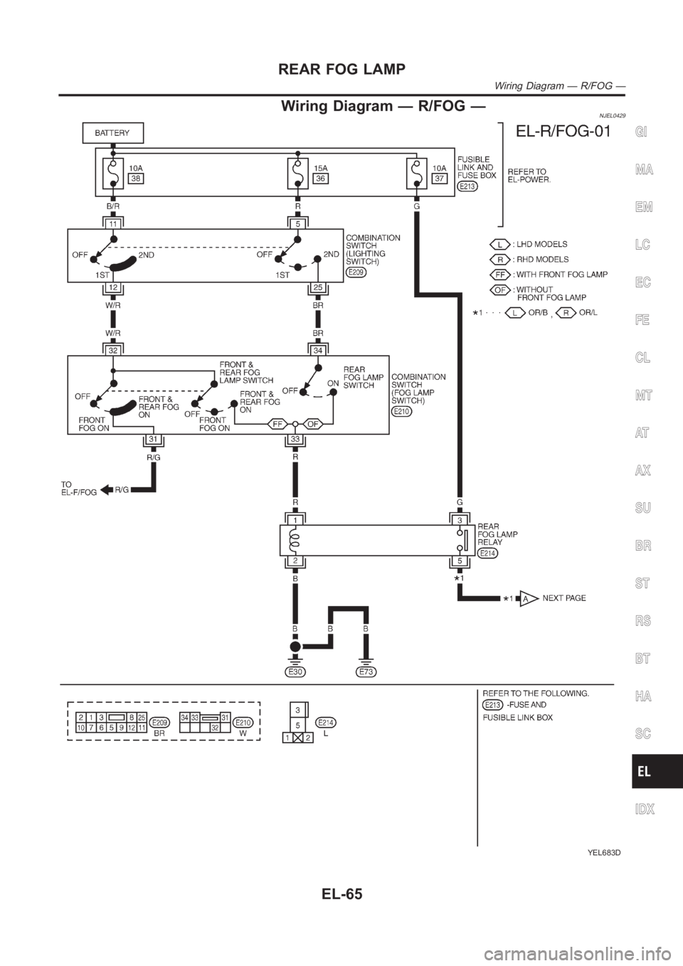
Wiring Diagram — R/FOG —NJEL0429
YEL683D
GI
MA
EM
LC
EC
FE
CL
MT
AT
AX
SU
BR
ST
RS
BT
HA
SC
IDX
REAR FOG LAMP
Wiring Diagram — R/FOG —
EL-65
Page 2402 of 3189
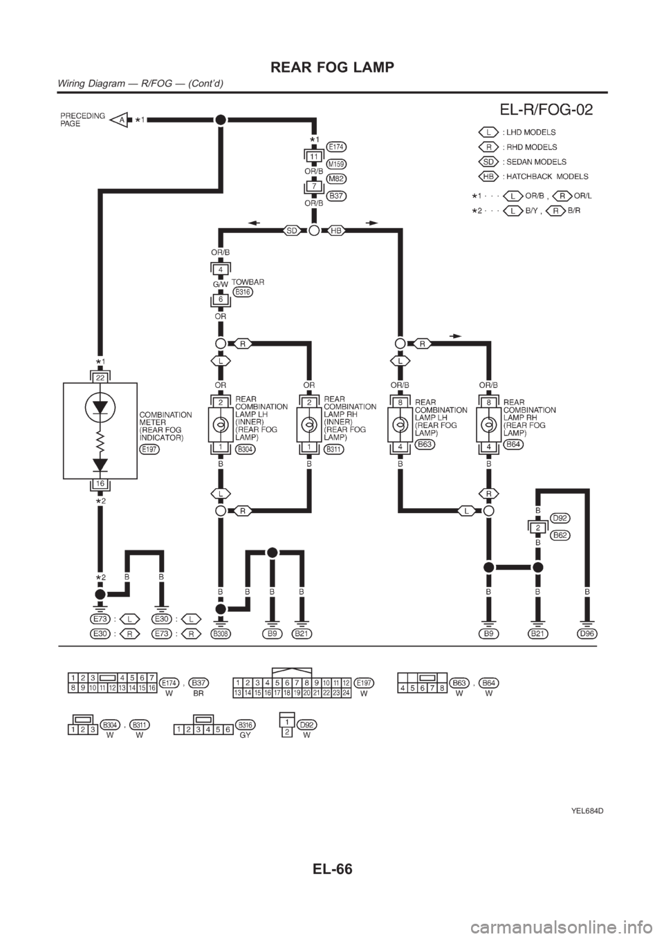
YEL684D
REAR FOG LAMP
Wiring Diagram — R/FOG — (Cont’d)
EL-66
Page 2403 of 3189
System Description/QG Engine Models and YD
Engine Models with Common Rail
NJEL0430TURN SIGNAL OPERATIONNJEL0430S01The turn signal lamps operation is controlled by the lighting switch whichis built into the combination switch
and smart entrance control unit.
Power is supplied at all times
through 15A fuse [No. 5, located in fuse block (J/B)]
to smart entrance control unit terminal 56
With the ignition switch in the ON or START position, power is supplied
through 10A fuse [No. 10, located in fuse block (J/B)]
to smart entrance control unit terminal 29
Ground is supplied to smart entrance control unit terminal 53 through bodygrounds F118 (QG engine models),
M28 and M67.
LH TurnNJEL0430S0101When the turn signal switch is moved to the L position, ground is supplied from body grounds E30 and E73
to
smart entrance control unit terminal 25
through turn signal switch terminal 3
With ground is supplied, smart entrance control unit controls the flashing of the LH turn signal lamps.
Power is supplied from smart entrance control unit terminal 64
to front turn signal lamp LH terminal 1,
to side turn signal lamp LH terminal 2,
to rear combination lamp LH terminal 2 (for sedan models) or
to rear combination lamp LH terminal 5 (for hatchback models).
Ground is supplied to the front turn signal lamp LH terminal 2 through body grounds E30 and E73.
Ground is supplied to the side turn signal lamp LH terminal 1 through body grounds E30 and E73.
Ground is supplied to the rear combination lamp LH terminal 1 through body grounds B9, B21 and B308 (for
sedan models).
Ground is supplied to the rear combination lamp LH terminal 4 through body grounds B9, B21 and D96 (for
hatchback models).
With power and ground supplied, the smart entrance control unit controls the flashing of the LH turn signal
lamps, and smart entrance control unit sent flashing indicator signal (LHturn signal) to combination meter with
CAN communication line.
to combination meter terminal 26 and 27
from smart entrance control unit terminal 8 and 11.
Turn signal LH is flushing of combination meter.
RH TurnNJEL0430S0102When the turn signal switch is moved to the R position, ground is supplied from body grounds E30 and E73
to
smart entrance control unit terminal 26
through turn signal switch terminal 2
With ground is supplied, smart entrance control unit controls the flashing of the RH turn signal lamps.
Power is supplied from smart entrance control unit terminal 63
to front turn signal lamp RH terminal 1,
to side turn signal lamp RH terminal 2,
to rear combination lamp RH terminal 2 (for sedan models) or
to rear combination lamp RH terminal 5 (for hatchback models).
Ground is supplied to the front turn signal lamp RH terminal 2 through body grounds E30 and E73.
Ground is supplied to the side turn signal lamp RH terminal 1 through body grounds E30 and E73.
Ground is supplied to the rear combination lamp RH terminal 1 through body grounds B9, B21 and B21 (for
sedan models).
Ground is supplied to the rear combination lamp RH terminal 4 through body grounds B9, B21 and D96 (for
GI
MA
EM
LC
EC
FE
CL
MT
AT
AX
SU
BR
ST
RS
BT
HA
SC
IDX
TURN SIGNAL AND HAZARD WARNING LAMPS
System Description/QG Engine Models and YD Engine Models with Common Rail
EL-67
Page 2404 of 3189
hatchback models).
With power and ground supplied, the smart entrance control unit controls the flashing of the RH turn signal
lamps, and smart entrance control unit sent RH turn signal to combination meter with CAN communication
line.
to combination meter terminal 26 and 27
from smart entrance control unit terminal 8 and 11.
HAZARD LAMP OPERATIONNJEL0430S02Power is supplied at all times
through 15A fuse [No. 5, located in fuse block (J/B)]
to smart entrance control unit terminal 56
With the hazard switch in the ON position, ground is supplied from body grounds F118 (QG engine models),
M28 and M67 to
smart entrance control unit terminal 30
through hazard switch terminals 1 and 3
With ground is supplied, smart entrance control unit controls the flashing of the hazard warning lamps.
Power is supplied from smart entrance control unit terminal 64
to front turn signal lamp LH terminal 1,
to side turn signal lamp LH terminal 2,
to rear combination lamp LH terminal 2 (for sedan models) or
to rear combination lamp LH terminal 5 (for hatchback models).
Power is supplied from smart entrance control unit terminal 63
to front turn signal lamp RH terminal 1,
to side turn signal lamp RH terminal 2,
to rear combination lamp RH terminal 2 (for sedan models) or
to rear combination lamp RH terminal 5 (for hatchback models).
Ground is supplied to terminal 2 each front turn signal lamp through body grounds E30 and E73.
Ground is supplied to terminal 1 each side turn signal lamp through body grounds E30 and E73.
Ground is supplied to terminal 1 of rear combination lamp through body grounds B9 and B21 and B308 (for
sedan models).
Ground is supplied to terminal 4 of rear combination lamp through body grounds B9, B21 and D96 (for hatch-
back models).
With power and ground supplied, the smart entrance control unit controls the flashing of the hazard warning
lamps, and smart entrance control unit sent flashing indicator signal (hazard warning signal) to combination
meter with CAN communication line.
to combination meter terminal 26 and 27
from smart entrance control unit terminals 8 and 11.
HAZARD REMINDER OPERATION FOR MULTI-REMOTE CONTROL SYSTEMNJEL0430S04When the doors are locked or unlocked by multi-remote controller, smart entrance control unit controls turn
lamps hazard reminder flashes as follows.
Locked operation: Flash once
Unlock operation: Flash twice
TURN SIGNAL AND HAZARD WARNING LAMPS
System Description/QG Engine Models and YD Engine Models with Common Rail(Cont’d)
EL-68
Page 2405 of 3189
![NISSAN ALMERA N16 2003 Electronic Repair Manual System Description/YD Engine Models with
Common Rail and K9K Engine Models
=NJEL0547TURN SIGNAL OPERATIONNJEL0547S01Power is supplied at all times
through 15A fuse [No. 5, located in fuse block (J/B)] NISSAN ALMERA N16 2003 Electronic Repair Manual System Description/YD Engine Models with
Common Rail and K9K Engine Models
=NJEL0547TURN SIGNAL OPERATIONNJEL0547S01Power is supplied at all times
through 15A fuse [No. 5, located in fuse block (J/B)]](/img/5/57350/w960_57350-2404.png)
System Description/YD Engine Models with
Common Rail and K9K Engine Models
=NJEL0547TURN SIGNAL OPERATIONNJEL0547S01Power is supplied at all times
through 15A fuse [No. 5, located in fuse block (J/B)]
to time control unit terminal 9
With the ignition switch in the ON or START position, power is supplied
through 10A fuse [No. 10, located in fuse block (J/B)]
to time control unit terminal 1
Ground is supplied to time control unit terminal 16 through body grounds M28 and M67.
LH TurnNJEL0547S0101When the turn signal switch is moved to the L position, ground is supplied from body grounds E30 and E73
to
time control unit terminal 2
through turn signal switch terminal 3
With ground is supplied, time control unit controls the flashing of the LH turn signal lamps.
RH TurnNJEL0547S0102When the turn signal switch is moved to the R position, ground is supplied from body grounds E30 and E73
to
time control unit terminal 4
through turn signal switch terminal 2
With ground is supplied, time control unit controls the flashing of the RH turn signal lamps.
HAZARD LAMP OPERATIONNJEL0547S02Power is supplied at all times
through 15A fuse [No. 5, located in fuse block (J/B)]
to time control unit terminal 9
Ground is supplied to time control unit terminal 16 through body grounds M28 and M67.
With the hazard switch in the ON position, ground is supplied from body grounds M28 and M67 to
time control unit terminals 1 and 5
through hazard switch terminal 3
With ground is supplied, time control unit controls the flashing of the hazard warning lamps.
HAZARD REMINDER OPERATION FOR MULTI-REMOTE CONTROL SYSTEMNJEL0547S03When the doors are locked or unlocked by multi-remote controller, time control unit controls turn lamps haz-
ard reminder flashes as follows.
Locked operation: Flash once
Unlock operation: Flash twice
GI
MA
EM
LC
EC
FE
CL
MT
AT
AX
SU
BR
ST
RS
BT
HA
SC
IDX
TURN SIGNAL AND HAZARD WARNING LAMPS
System Description/YD Engine Models with Common Rail and K9K Engine Models
EL-69
Page 2406 of 3189
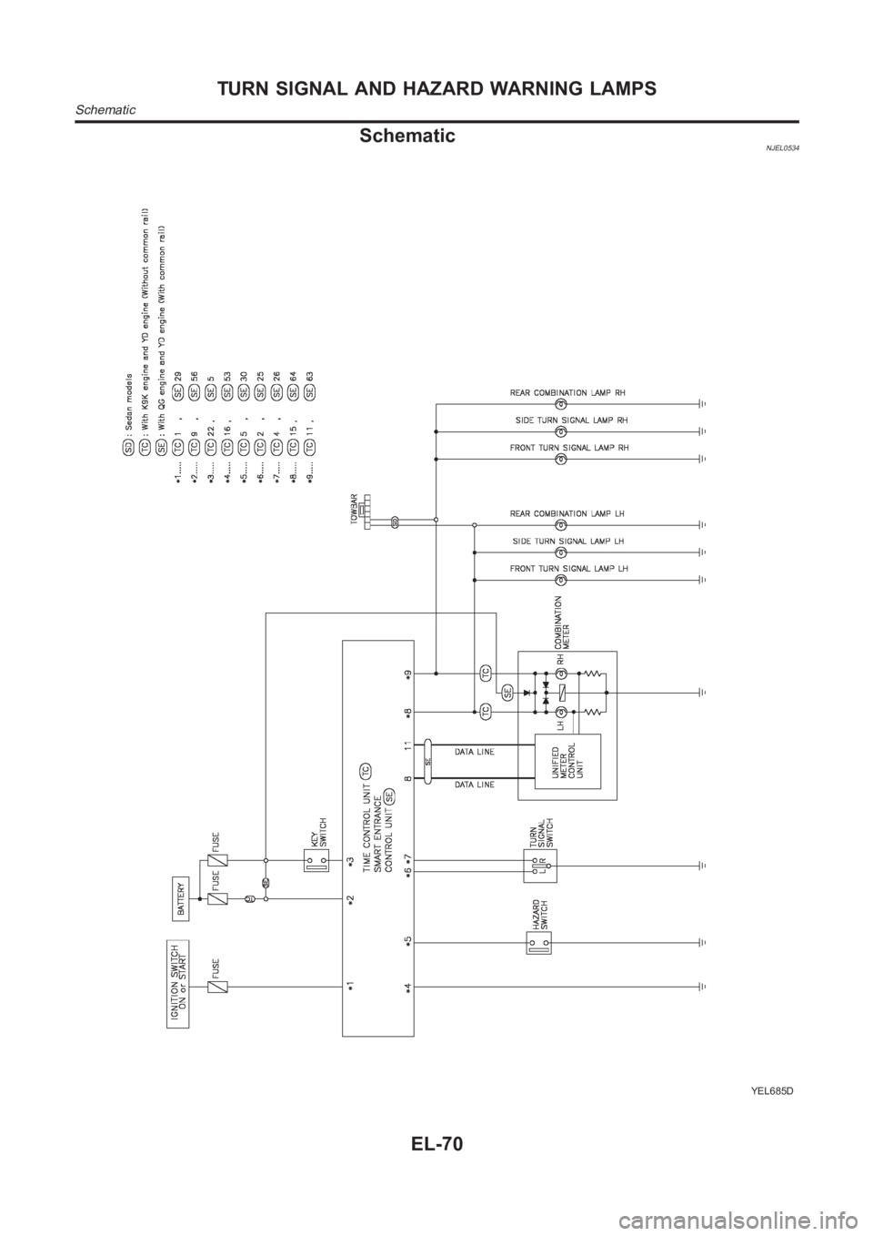
SchematicNJEL0534
YEL685D
TURN SIGNAL AND HAZARD WARNING LAMPS
Schematic
EL-70
Page 2407 of 3189
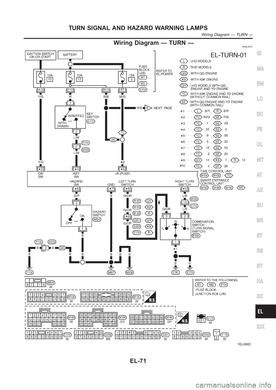
Wiring Diagram — TURN —NJEL0431
YEL686D
GI
MA
EM
LC
EC
FE
CL
MT
AT
AX
SU
BR
ST
RS
BT
HA
SC
IDX
TURN SIGNAL AND HAZARD WARNING LAMPS
Wiring Diagram — TURN —
EL-71
Page 2408 of 3189
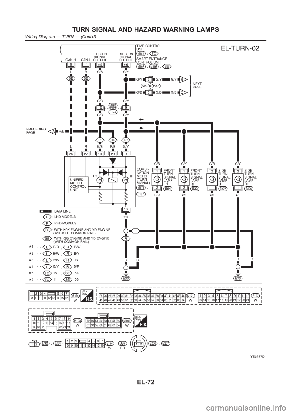
YEL687D
TURN SIGNAL AND HAZARD WARNING LAMPS
Wiring Diagram — TURN — (Cont’d)
EL-72
Page 2409 of 3189
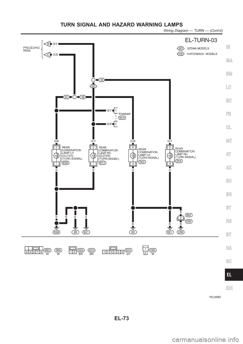
YEL688D
GI
MA
EM
LC
EC
FE
CL
MT
AT
AX
SU
BR
ST
RS
BT
HA
SC
IDX
TURN SIGNAL AND HAZARD WARNING LAMPS
Wiring Diagram — TURN — (Cont’d)
EL-73
Page 2410 of 3189
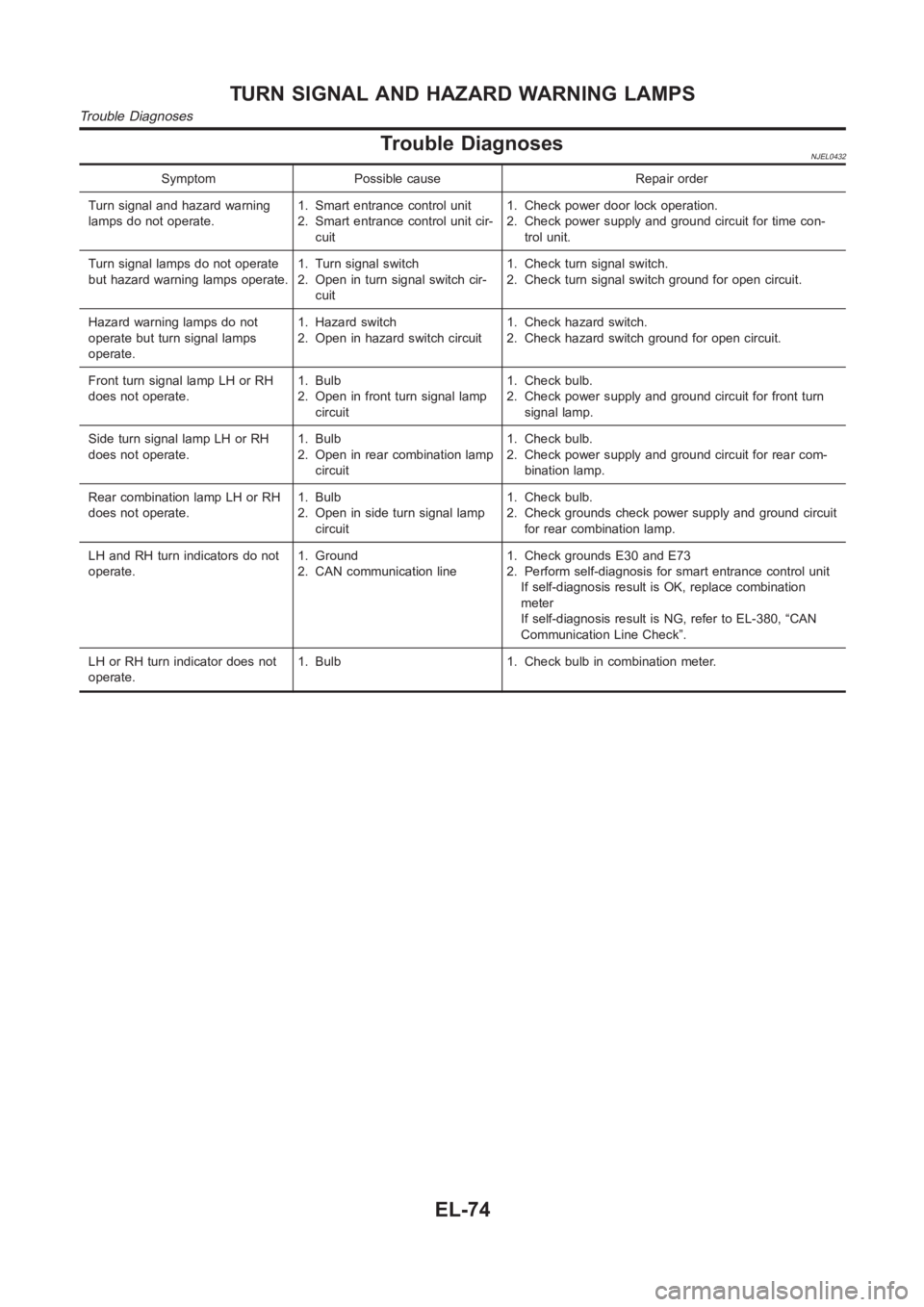
Trouble DiagnosesNJEL0432
Symptom Possible cause Repair order
Turn signal and hazard warning
lamps do not operate.1. Smart entrance control unit
2. Smart entrance control unit cir-
cuit1. Check power door lock operation.
2. Check power supply and ground circuit for time con-
trol unit.
Turn signal lamps do not operate
but hazard warning lamps operate.1. Turn signal switch
2. Open in turn signal switch cir-
cuit1. Check turn signal switch.
2. Check turn signal switch ground for open circuit.
Hazard warning lamps do not
operate but turn signal lamps
operate.1. Hazard switch
2. Open in hazard switch circuit1. Check hazard switch.
2. Check hazard switch ground for open circuit.
Front turn signal lamp LH or RH
does not operate.1. Bulb
2. Open in front turn signal lamp
circuit1. Check bulb.
2. Check power supply and ground circuit for front turn
signal lamp.
Side turn signal lamp LH or RH
does not operate.1. Bulb
2. Open in rear combination lamp
circuit1. Check bulb.
2. Check power supply and ground circuit for rear com-
bination lamp.
Rear combination lamp LH or RH
does not operate.1. Bulb
2. Open in side turn signal lamp
circuit1. Check bulb.
2. Check grounds check power supply and ground circuit
for rear combination lamp.
LH and RH turn indicators do not
operate.1. Ground
2. CAN communication line1. Check grounds E30 and E73
2. Perform self-diagnosis for smart entrance control unit
If self-diagnosis result is OK, replace combination
meter
If self-diagnosis result is NG, refer to EL-380, “CAN
Communication Line Check”.
LH or RH turn indicator does not
operate.1. Bulb 1. Check bulb in combination meter.
TURN SIGNAL AND HAZARD WARNING LAMPS
Trouble Diagnoses
EL-74